Note: Descriptions are shown in the official language in which they were submitted.
CA 03226282 2024-01-08
WO 2023/281275
PCT/GB2022/051767
IMPROVEMENTS IN OR RELATING TO A MICROFLUIDIC DEVICE
FIELD OF THE INVENTION
.. The present disclosure relates to a microfluidic device, and in particular,
a device for
manipulating a microdroplet using optically-mediated electrowetting (oEWOD).
BACKGROUND TO THE INVENTION
Design of devices for manipulating microdroplets using optically-mediated
electrowetting is driven by a number of competing effects and observed
phenomena.
When focussing on the efficiency of manipulation of microdroplets, it would be
preferable in many designs to maximise the speed at which the microdroplets
can be
manipulated. Improvements in droplet manipulation speed allows for higher
throughput of biological experiments. Another aspect of the efficiency of an
oEWOD
device is the reliability with which droplets can be held stationary within a
device,
with the minimum number of droplets being lost or moving from their holding
positions. The speed with which the microdroplets can be manipulated
correlates
zo .. supra-linearly with the voltage applied. The maximum voltage that can be
applied
dictates the dielectric thickness required to ensure that the device operates
below
the breakdown voltage of the dielectric layers. The literature therefore
teaches that
thick dielectric layers are required in order to operate safely at the high
voltages
required to maximise speed. The reliability of droplet holding is determined
by the
complex interplay between the droplet holding force and the strength of any
extraneous forces that might dislodge the droplets from their holding
locations,
particularly dielectrophoretic effects and the motion of the surrounding
carrier phase
and the constituents of the carrier phase.
It is against this background that the present invention has arisen.
CA 03226282 2024-01-08
WO 2023/281275
PCT/GB2022/051767
2
SUMMARY OF THE INVENTION
According to an aspect of the present invention, there is provided a device
for
manipulating a microdroplet using optically-mediated electrowetting, the
device
comprising a microfluidic space bounded by:
= a first composite wall comprising:
= a first substrate;
= a first conductor layer on the substrate;
= a photoactive layer on the first conductor layer; and
= a first continuous dielectric layer on the photoactive layer having
a thickness of less than 20 nm;
= a second composite wall comprising:
= a second substrate; and
= a second conductor layer on the substrate.
In some embodiments, the second composite wall further comprises a second
continuous dielectric layer on the second conductor layer having a thickness
of less
than 20 nm.
In some embodiments, the first and second composite walls are held apart to
form a
zo microfluidic space therebetween. The walls can be separated by a spacer
structure,
which may be formed by an interposing structure between the first and second
substrates, or it could be formed from the substrates of the first or second
composite
walls.
The spacer may be formed from a layer of photoresist, by a layer of pressure-
sensitive adhesive and/or by a layer of dry-film resist. Additionally or
alternatively, it
may be formed by etching structures and/or cavities in to a glass, fused
silica or
transparent plastic substrate that forms the first or second composite walls.
According to another aspect of the present invention there is provided a
device for
manipulating a microdroplet using optically-mediated electrowetting, the
device
comprising:
= a first composite wall comprising:
CA 03226282 2024-01-08
WO 2023/281275
PCT/GB2022/051767
3
= a first substrate;
= a first conductor layer on the substrate;
= a photoactive layer on the conductor layer; and
= a first continuous dielectric layer on the photoactive layer having
a thickness of less than 20 nm;
= a second composite wall comprising:
= a second substrate;
= a second conductor layer on the substrate; and
= a second continuous dielectric layer on the second conductor
layer having a thickness of less than 20 nm.
The design of devices for manipulating microdroplets using optically-mediated
electrowetting is driven by a number of competing effects and observed
phenomena.
There is a well acknowledged super linear correlation between the speed of
microdroplets and the voltage applied. The maximum voltage applied then
dictates
the dielectric thickness required. In order to optimise the speed of the
microdroplets,
it would therefore be expected that the voltage applied would be maximised and
therefore the thickness of the dielectric would be increased to accommodate
this.
However, the inventors have found that high voltages have their own associated
problems in relation to practical delivery.
zo Experimentally the inventors discovered that when increasing the applied
voltage the
maximum achievable oEWOD speed increases rapidly as expected. However, the
inventors also observed that the ability to hold droplets stationary rapidly
decreases
with increasing voltage due to a previously unobserved driving force.
Initially this
presents as a characteristic random motion of the droplets around their target
locations, as the voltage is increased further the speed of this random motion
increases until this random motion overpowers the oEWOD holding force and
control
of the droplet is lost. This effectively imposes a maximum voltage thus
reducing the
maximum speed far below what is initially expect and predicted in the
literature.
There are two states that dictate the voltage driven response of an oEWOD
system,
the "on" and the "off" states, corresponding to the illuminated and non-
illuminated
regions of the device. In an idealised oEWOD device the voltage applied in the
on-
regions of the device would be exactly nil, and only the 'on' state regions
would apply
CA 03226282 2024-01-08
WO 2023/281275
PCT/GB2022/051767
4
a voltage. In an oEWOD device the spatially-varying optically controlled
voltage on
the surface alters the contact angle between the droplet and the surface and
so
imparts a driving force or a holding force on the droplet. When holding a
droplet, the
droplet will partially reside in the "on" state and partially in the `off
state, with the
spatial extent of each state determined by the size of the illuminated region.
The
contrast in voltage between the "on" and "off" states creates the holding
force. As the
applied voltage is increased the field strength of both states increases. The
increase
in field strength of the `on' state leads to an increase in device performance
as it
increases the electrowetting force. The increase in field strength of the `off
state will
partially counteract this increase in force. However, as the ratio between
these two
states remains constant and the force depends on the square of the field there
is an
overall increase in the oEWOD force. Therefore, the literature teaches that
with
increasing voltage the skilled person would expect to see an improvement in
both
holding and droplet movement.
This is clearly in opposition to the observations by the inventors, where the
inventors
observe an increase in movement speed but a decrease in the ability to hold a
droplet stationary with increasing voltage. Thus, the inventors theorise that
this
phenomenon is only explicable through a super-linear (faster than square)
dependence of the unwanted driving force on the field strength of the "off'
state.
zo Therefore, the performance of the device, as disclosed herein, can be
improved by
designing the structure of the device to reduce the strength of the `off'
state rather
than by maximising the strength of the `on' state, as has been the focus of
the
literature within the field.
A logical approach to achieving this would be to increase the thickness of the
photoactive layer. However, this is unsuitable for applications where a large
number
of droplets need to be manipulated simultaneously as it drastically increases
the
optical power requirements. Moreover, an increased thickness of the
photoactive
layer is inadequate for facilitating the parallel manipulation of many
thousands of
droplets simultaneously. Therefore rather than minimising the `off state
through a
change to the photoactive layer, the inventors explored the impact of the
capacitance
of the dielectric layer. In this counter-intuitive focus on the `off state,
the inventors
have found that by decreasing the thickness of the dielectric layer, a higher
fraction
of the voltage would drop across the photoconductive layer and hence, the
field
CA 03226282 2024-01-08
WO 2023/281275
PCT/GB2022/051767
strength at the surface of the dielectric would decrease. The inventors have
therefore
reduced the dielectric thickness of device by approximately five times below
what is
recommended in the literature. This has resulted in a huge increase in device
performance through mitigation of the 'off' state droplet holding failure mode
allowing
5 higher
operational voltages to be reached and therefore higher oEWOD force, while
requiring the same level of illumination.
The first dielectric layer may be deposited onto the photoactive layer by
atomic layer
deposition. Additionally or alternatively, the second dielectric layer may be
deposited
onto the photoactive layer.
Surprising it has been discovered that by providing the first and/or second
dielectric
layers with a continuous layer of thickness of less than 20 nm results in the
droplets
being more stable and therefore, the droplets are stationary on the substrate.
In
contrast, the inventors have found that increasing the first and/or second
dielectric
layers to a thickness of above 20 nm can result in more uncontrolled droplet
movement on the substrate and therefore, droplets are more likely to exhibit
uncontrolled motion deviating from the illuminated regions. As a consequence,
uncontrolled droplets can make it more difficult for accurate and efficient
oEWOD
operations for example, merging or splitting of droplets. In some embodiments,
the
zo first
and/or second dielectric layer may be a thickness of between 1 nm to 20 nm, or
it may be 2 nm to 20 nm, 3 nm to 20 nm, 4 nm to 20 nm, 5 nm to 20 nm, 6 nm to
20
nm, 7 nm to 20 nm, 8 nm to 20 nm, 9 nm to 20 nm, 10 nm to 20 nm, 12 m to 20
nm,
14 nm to 20 nm, 15 nm to 20 m or 18 nm to 20 nm. It may also be 1 to 15 nm, 1
to
10 nm, Ito 5 nm, 5 to 10 nm, 5 to 15 nm or 10 to 15 nm.
The first substrate and/or the second substrate may be transparent. The first
conductor layer and/or the second conductor layer may be transparent.
The device may further comprise an Alternating Current (NC) source to provide
a
voltage across the first and second composite walls connecting the first and
second
conductor layers; at least one source of electromagnetic radiation having an
energy
higher than the bandgap of a first photoexcitable layer adapted to impinge on
the
photoactive layer to induce corresponding ephemeral electrowetting locations
on the
CA 03226282 2024-01-08
WO 2023/281275
PCT/GB2022/051767
6
surface of the first dielectric layer; and a microprocessor for controlling
the source of
electromagnetic radiation to manipulate the points of impingement of the
electromagnetic radiation on the photoactive layer so as to vary the
disposition of the
ephemeral electrowetting locations thereby creating at least one
electrowetting
pathway along which the microdroplet may be caused to move.
The device may further comprise an interstitial layer of silicon oxide. The
interstitial
layer of silicon oxide is provided on the first and/or the second dielectric
layers. The
advantage of the interstitial layer is that it can be used as a binding layer
for a anti or
non-fouling layer. The interstitial layer is provided between the dielectric
layer and
the hydrophobic layer. The thickness of the interstitial layer may be between
0.1 nm
to 5 nm. The thickness of the interstitial layer can be more than 0.1, 0.25,
0.5, 0.75,
1, 1.5, 2, 2.5, 3, 3.5, 4 or 4.5 nm, or it may be less than 5 nm, 4.5, 4, 3.5,
3, 2.5, 2,
1.5, 1, 0.75, 0.5 or 0.25 nm.
The exposed surfaces of the first and second composite walls may be disposed
less
than 200 pm apart to define a microfluidic space adapted to contain the
microdroplet.
The microfluidic space may be between 2 and 50 pm in width. In some
embodiments, the microfluidic space is more than 2, 4, 6, 8, 10, 12, 14, 16,
18, 20,
zo 22, 24, 26, 28, 30, 32, 34, 36, 38, 40, 42, 44, 46 or 48 pm. In some
embodiments,
the microfluidic space may be less than 50, 48, 46, 44, 42, 40, 38, 36, 34,
32, 30, 28,
26, 24, 22, 20, 18, 16, 14, 12, 10, 8, 6 or 4 pm.
The exposed surfaces of the first and second composite walls may include one
or
more spacers for holding the first and second walls apart by a predetermined
amount
to define a microfluidic space adapted to contain the microdroplet. The
physical
shape of the spacers may be used to aid the splitting, merging and elongation
of
microdroplets in the device. The spacer can be, but is not limited to, a blade
shaped
structure, a wedge structure, a pillar, a hydrophilic patch, a narrow channel,
or it
could be a surface dimple.
In some embodiments, the microdroplets may contain one or more cells. The
microdroplets may also contain a medium, such as a cell medium and/or a buffer
solution.
CA 03226282 2024-01-08
WO 2023/281275
PCT/GB2022/051767
7
The NC source may be configured to provide a voltage of between OV and 100V
across the first and second composite walls connecting the first and second
conductor layers. In some embodiments, the voltage provided may be between OV
to
50V, 0.1 V, 0.1V to 2V, 3 to 4 V or it could be between OV to 10V. In some
embodiments, the A/C source can be configured to provide a voltage of more
than 0,
5, 10, 15, 20, 25, 30, 35, 40, 50, 60, 70, 80 or 90 V or it may be less than
90, 80, 70,
60, 50, 45, 40, 35, 30, 25, 20, 15, 10 or 5V.
The first and second composite walls may further comprise first and second
anti-
fouling layers on respectively the first and second dielectric layers. The
anti-fouling
layer on the second dielectric layer may be hydrophobic.
The source(s) of electromagnetic radiation may comprise a pixellated array of
light
reflected from or transmitted through such an array.
The electrowetting locations may be crescent-shaped in the direction of travel
of the
microdroplets.
The device may further comprise a photodetector to detect an optical signal in
the
microdroplet located within or downstream of the device. The optical signal
may be a
fluorescence signal.
zo The device may further comprise an upstream inlet to generate a medium
comprised
of an emulsion of aqueous microdroplets in an immiscible carrier fluid. The
carrier
fluid may optionally be inert.
The device may further comprise an upstream inlet to induce a flow of a medium
comprised of an emulsion of aqueous microdroplets in an immiscible carrier
fluid
through the microfluidic space via an inlet port into the microfluidic space.
The first and second composite walls which define the microfluidic space
therebetween may form the periphery of a cartridge or chip.
The device may further comprise a plurality of first electrowetting pathways
running
concomitantly to each other.
CA 03226282 2024-01-08
WO 2023/281275
PCT/GB2022/051767
8
The device may further comprise a plurality of second electrowetting pathways
adapted to intersect with the first electrowetting pathways to create at least
one
microdroplet-coalescing location.
The device may further comprise an upstream inlet for introducing the
microdroplet
.. into the microfluidic space, in which the diameter of the microdroplet is
more than
20% greater than the width of the microfluidic space.
The second composite wall may further comprise a second photoexcitable layer
and
the source of electromagnetic radiation may also impinge on the second
photoexcitable layer to create a second pattern of ephemeral electrowetting
locations
which can also be varied.
The source of electromagnetic radiation may be an LED light source, which may
provide electromagnetic radiation at a level of 0.005 to 0.1Wcm-2. In
some
embodiments, the source of electromagnetic radiation is at a level of 0.005 to
0.1Wcm-2, or it could be more than 0.005, 0.0075, 0.01, 0.025, 0.05 or 0.075
Wcm-2.
In some embodiments, the source of electromagnetic radiation is at a level may
be
less than 0.1, 0.075, 0.05, 0.025, 0.01, 0.0075, 0.005 or 0.0025 Wcm-2.
The first transparent conductor layer on the substrate may be a thickness in
the
range 70 to 250nm. The photoactive layer may be activated by electromagnetic
radiation in the wavelength range 400 t01000nm on the conductor layer, which
may
zo have a thickness in the range 300 to 1000nm.
In some embodiments, the photoactive layer can be made out of amorphous
silicon.
In some embodiments, microdroplets can be passed through a microfluidic space
defined by two opposing walls where each of the walls includes a dielectric
layer with
a sufficiently low voltage applied across the dielectric layers so as to be
below the
dielectric breakdown voltage of the dielectric layers. The use of the two
dielectric
layers with a sufficiently low voltage across the dielectric layers not only
prevents
destructive ionization of conductive droplets but substantially eliminates the
adverse
effects of dielectric pinhole defects on the droplets which unexpectedly
improves
performance notwithstanding the reduction in electowetting forces resulting
from the
use of two dielectric layers. As a consequence, the optically-mediated
electrowetting
can be achieved using a low power source of illumination such as, for example,
CA 03226282 2024-01-08
WO 2023/281275
PCT/GB2022/051767
9
LEDs generating as low as 0.01W/cm2 for simultaneously manipulating thousands
of
droplets. In the case of an embodiment comprising a large-area microfluidic
device
with area greater than 1cm x 1cm, the device is suitable for manipulating more
than
10,000 droplets in parallel, more than 50,000 droplets, more than 100,000
droplets
or more than 1,000,000 droplets in the case of a very large-area device.
In some embodiments a large area device can be utilised for handling many
thousands of droplets. The inventors had tried to previously build a larger
device
using a single dielectric layer for handling droplets in parallel, however the
inventors
encountered defective areas where droplets could not move. Through
experimentation and test, the inventors found pinhole defects to be an
important
limitation of device performance, especially as devices became larger.
The dielectric layers always have sparse pinhole defects, whereby they become
conducting in a small, isolated region. Known optimized processes can give
densities of circa 38 pinholes per cm2. A pinhole defect can trap a droplet
and make
it impossible to move. The effect is more profound when using droplets of
conducting
media such as buffer solutions.
In some embodiments, there is provided a two dielectric layer structure that
can be
used below the dielectric breakdown. When run below the breakdown voltage, the
two sided dielectric layer structure can give the novel effect of largely
negating the
zo effect of pinhole defects. With the dielectric disposed over both top
and bottom of the
droplets, a conducting path could only be formed if a pinhole defect in the
first
dielectric layer directly lined up with a pinhole defect in the second
dielectric layer.
The probability of this occurring is very, very small. This pinhole-mitigation
feature
achieved by the presence of the second dielectric layer is key to permitting
the
simultaneous manipulation of thousands of droplets in a relatively large area.
In the case of a large area device or a very large area device suitable for
manipulating more than 100,000 droplets or even more than 1,000,000 droplets
in
parallel the number of pinhole defects becomes an important limitation in the
device
performance, because the probability of a single droplet contacting a pinhole
defect
becomes exceptionally high. A single droplet trapped on a pinhole defect may
block
the motion of other droplets in the device and so impair or interrupt the
operation of
the system. As such the advantage of the present invention in negating the
effect of
CA 03226282 2024-01-08
WO 2023/281275
PCT/GB2022/051767
pinhole defects is exceptionally important in the operation of a very large
area device
containing large numbers of microdroplets.
According to another aspect of the present invention, there is provided a
cartridge
comprising: a reservoir containing a liquid sample; an emulsifier in a fluidic
circuit
5 with
the reservoir, the emulsifier is configured to generate a medium comprised of
an
emulsion of aqueous microdroplets in an immiscible carrier fluid; an inlet
channel
provided downstream of the emulsifier, wherein the inlet channel is configured
to
receive the medium comprised of the emulsion of aqueous microdroplets in the
immiscible carrier fluid from the emulsifier; a device according to any one of
the
10 aspects of the present invention, whereby the device comprises at least
an inlet port
and the device is in fluid communication with the inlet channel; and a pumping
system provided to induce the flow of the liquid sample to the emulsifier
and/or
induce the flow of the medium comprised of the emulsion of aqueous
microdroplets
in the immiscible carrier fluid through the device.
.. Suitably, the aqueous fluids within the cartridge may be biological fluids
such as cell
media, and they may contain cells, beads, particles, drugs, biomolecules or
other
biological entities. These entities may be viruses, DNA or RNA molecules,
stimulants, cytokines, nutrients and dissolved gases. As such the design of
the
cartridge channels and structures may be optimised such that the dispersion
and
zo integrity of the biological fluids is preserved, particularly by
selection of well-matched
channels of even hydraulic diameter and minimal fluid shear.
In some embodiments, the cartridge may further comprise one or more valves
provided at the inlet port of the device, wherein the valve controls the flow
of the
medium, comprised of the emulsion of aqueous microdroplets in the immiscible
carrier fluid, through the device.
In some embodiments, the emulsifier may be a step emulsifier. In some
embodiments, several emulsifiers may be provided, each of which is provided
with
an inlet channel.
In some embodiments, the pumping system can include, but is not limited to, a
pump, a head reservoir, an accumulator and/or a pressure source. It will be
further
appreciated that the skilled person in the art would know other pumping system
that
CA 03226282 2024-01-08
WO 2023/281275
PCT/GB2022/051767
11
could be used to induce the flow of the liquid sample to the emulsifier and/or
induce
the flow of the medium through the device.
A number of technologies are known in the art for the formation of aqueous
emulsions of microdroplets surrounded by an immiscible carrier phase. These
include cross-flow emulsion generators, 1-junction generators and step
emulsification devices. Cross-flow emulsion generators, T-junction emulsion
generators and other related devices are typically used to make microdroplets
of
variable sizes. The size distribution of the microdroplets is dependent on the
flow
conditions created at the junction where oil and aqueous material intersect.
Furthermore, the microdroplet size is dependent on the fluid properties, such
as the
interfacial tensions and viscosities of the running fluids. As such, it is
necessary to
precisely control and adjust the flow rate of the fluids entering these types
of
emulsion generators in order to provide a uniform and repeatable size
distribution of
droplets into the oEWOD device.
Advantageously, a step emulsifier generates emulsion with a microdroplet size
distribution that has a minimal dependency on the flow velocities at the
emulsification
junction. The size of the microdroplets is determined predominantly by the
physical
dimensions of the emulsification nozzle, as well as the material properties of
the
running fluids. Whilst both step emulsifiers and other emulsifiers are
sensitive to the
properties of the running fluids, the degree of dependency on interfacial
tension and
viscosity is considerably reduced in a step emulsifier device. As such, it is
not
necessary to precisely control and adjust flow parameters in order to correct
the
microdroplet size distribution emitting from the emulsifier. It can be
operated with a
simple fixed-flow-rate or fixed-pressure system. It is particularly suitable
for operation
with an oEWOD device because it avoids the requirement for inspection and
optical
access to an emulsifier device in a location, which might otherwise overlap
with the
optical assembly used for operation of the OEWOD device. It avoids the
complexity
and cost of introducing a plurality of inspection and microdroplet size
monitoring
devices in order to monitor and control a plurality of emulsifiers being
operated within
one cartridge assembly. Therefore, a number of independent step emulsifiers
can be
connected to different inlets on the oEWOD device to provide fluidically
isolated
emulsion-generating input paths between the aqueous input and the oEWOD
device.
The use of fluidically-isolated input paths allows for the oEWOD device to
receive a
CA 03226282 2024-01-08
WO 2023/281275
PCT/GB2022/051767
12
set of independent emulsion inputs formed from different aqueous input
materials
without the possibility of cross-contamination between them.
In some embodiments, the cartridge assembly may contain up to eight
emulsifiers. In
some embodiments, the cartridge assembly may contain at least 1, 2, 3, 4, 5, 6
or 7
emulsifiers. In some embodiments, the cartridge assembly may contain between 8
and 12 emulsifiers. In some embodiments, the cartridge assembly may contain
between 12 to 20, 20 to 30, 30 to 50 or 50 t0100 emulsifiers.
The emulsifiers may be interchangeable by the user such that the user can
choose a
suitable type of emulsifier for their intended purposes. For example, the user
may
configure a cartridge with emulsifiers that provide a particular microdroplet
size
range. The user may choose a set of emulsifiers each providing microdroplets
with a
different size range, or a sub-selection of size ranges. In some embodiments,
the
emulsifiers may be configured to generate microdroplets of volumes in the
range 14
pL to 180pL, or microdroplets in the range 180pL to 500pL, or in the range
500pL to
1.2nL. The emulsifiers may also be configured to provide microdroplets of
volume
less than 14pL, particularly in the size range 10fL to 50fL or between 50fL
and 14pL.
In some embodiments, the emulsifiers may be configured to generate
microdroplets
of more than 1.2nL, including at least the ranges of 1.2nL to 4nL. In the case
where
the emulsifiers are step emulsifiers, it is possible to alter the volume of
the
microdroplets by changing the geometry of the emulsification nozzle,
particularly
changing the height of the nozzle in the minor axis of the rectangular nozzle.
Furthermore, it is possible to parallelise the operation of a set of step
emulsifier
nozzles within a single emulsifier device, so that multiple emulsification
nozzles are
connected to a single aqueous input. The connected nozzles can run
independently
with variation in speeds determined by the complex interplay between the
interconnected junctions. The emulsifiers can all generate microdroplets of
substantially uniform size determined by the physical size of the nozzles.
This allows
for a large number of generators running in parallel at low flow velocities,
eliminating
the deleterious effects of shear that can damage cells and other biological
materials.
It also allows the emulsifier to continue generating emulsion despite the
partial
occlusion or blocking of some nozzles that is the occasional consequence of
running
biological material comprising particulates through narrow nozzle apertures.
CA 03226282 2024-01-08
WO 2023/281275
PCT/GB2022/051767
13
According to an aspect of the present invention, there is provided a species
screened by the device, apparatus, cartridge or method as disclosed herein.
According to an aspect of the present invention, there is provided a species
selected
by the device, apparatus, cartridge or method as disclosed herein.
According to an aspect of the present invention, there is provided a species
isolated
by the device, apparatus, cartridge or method as disclosed herein.
According to an aspect of the present invention, there is provided a species
made by
the device, apparatus, cartridge or method as disclosed herein.
The species may be chemical, biochemical, or biological in nature.
For example, the present invention may provide an agonist/antagonist to an
entity as
identified by the screening, selection and/or isolation method disclosed
herein. The
present invention may provide an agonist/antagonist to an entity as identified
by the
screening, selection and/or isolation method disclosed herein, for use in
therapy.
The entity may be chemical, biochemical, or biological in nature.
According to an aspect of the present invention, there is provided a use of
the
device, apparatus, cartridge, method or species as disclosed herein.
According to an aspect of the present invention, there is provided a use of
the
device, apparatus, cartridge, method or species as disclosed herein in
therapy.
The present invention may provide for a use of the device, apparatus,
cartridge,
zo method
or species as disclosed herein in making a product. The product made may
be chemical, biochemical, or biological in nature.
The use may be peptide synthesis. The use may be synthetic biology. The use
may
be cell line engineering or development. The use may be cell therapy. The use
may
be drug discovery. The use may be antibody discovery.
According to an aspect of the present invention, there is provided a use of
the
device, apparatus, cartridge, method or species as disclosed herein in
analysis.
The analysis may be physical, chemical, or biological.
The use may be sub-cellular imaging. The use may be high content imaging.
CA 03226282 2024-01-08
WO 2023/281275
PCT/GB2022/051767
14
The use may be diagnostics.
The use may be a biological assay. The biological assay may be high throughput
screening. The biological assay may be ELISA.
The use may be cell secretion.
The use may be QC safety profiling.
FIGURES
The invention will now be further and more particularly described, by way of
example
only, and with reference to the accompanying drawings, in which:
Figures 1A and Figure 1B show two oEWOD device configurations according to the
present invention;
Figure 2 provides an equivalent circuit diagram for the oEWOD configuration
shown
schematically in Figures 1A and 1B;
Figure 3 shows a voltage plot of the critical voltages within oEWOD devices
having
different thicknesses of dielectric layer;
Figure 4 shows a flow-chart of the equilibrium of surfactant between various
states
within the oEWOD device; and
zo Figures 5A and 5B show the unwanted motion of droplets within oEWOD devices
when they are held near-stationary.
DETAILED DESCRIPTION
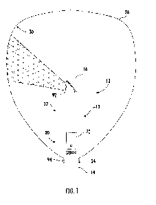
Referring to Figure 1A, there is provided a microfluidic device and in
particular, an
oEWOD device 100. The oEWOD device as illustrated in Figure 1A comprises: a
first
composite wall 102 comprised of a first substrate 104, which can be made out
of
glass, a first conductor layer 106 on the substrate 104, the first conductor
layer 106
having a thickness in the range 70 to 250nm; a photoactive layer 108 activated
by
CA 03226282 2024-01-08
WO 2023/281275
PCT/GB2022/051767
electromagnetic radiation in the wavelength range 400-850nm on the conductor
layer
106, the photoactive layer 108 having a thickness in the range 300-1500nm and
a
first dielectric layer 110 on the photoactive layer 108. The first dielectric
layer 110 is
formed as a continuous layer that has a thickness of less than 20nm. The lower
5 bound for the thickness of the layer will be dictated, at least in part,
by the
methodology of providing such a thin layer that must be continuous. However,
theoretically it could have a thickness of between 0.1 nm to 20 nm. The first
conductor can be transparent.
The device 100 also comprises a second composite wall 112 comprising: a second
10 substrate 114, which can be made out of glass and a second conductor
layer 116 on
the substrate 114. The second conductor can be transparent. The second
conductor
layer 116 may have a thickness in the range 70 to 250nm. A second dielectric
layer
118 may be on the second conductor layer 116, where the second dielectric
layer
118 has a thickness of less than 20nm. As with the first dielectric layer, the
second
15 dielectric layer must be continuous and the practical lower bound for
the thickness is
dictated by manufacturing constraints although it could be between 1 nm to 20
nm.
The exposed surfaces of the first 110 and second 118 continuous dielectric
layers
are disposed 20 to 180pm apart to define a microfluidic space 121 adapted to
contain microdroplets 122.
zo The photoactive layer 108 is made out of amorphous silicon. The first and
second
conductor layers are made out of ITO.
An interstitial binding layer 124 is provided on the first dielectric layer
110 and can
also be provided on the second dielectric layer 118. The thickness of the
interstitial
layer may be between 0.1 nm to 5 nm. The thickness of the interstitial layer
can be
more than 0.1, 0.25, 0.5, 0.75, 1, 1.5, 2, 2.5, 3, 3.5, 4 or 4.5 nm, or it may
be less
than 5 nm, 4.5, 4, 3.5, 3, 2.5, 2, 1.5, 1, 0.75, 0.5 or 0.25 nm. The advantage
of the
interstitial layer is that it can be used as a binding layer for an anti-
fouling or non-
fouling layer, which may be hydrophobic. In some embodiments, not illustrated
in the
accompanying drawings, the interstitial binding layer may be omitted. In such
.. embodiments, the hydrophobic layer is applied directly to the first
dielectric layer.
CA 03226282 2024-01-08
WO 2023/281275
PCT/GB2022/051767
16
A hydrophobic layer 126 is provided on the interstitial binding layer 124. An
example
of a hydrophobic layer could be a fluorosilane or fluorosiloxane. The
interstitial
binding layers 124 are optional and the channel walls 120 can be made of SU8,
or it
may be part of the glass structure. The interstitial layer 124 is provided
between the
s dielectric layer 110, 118 and the hydrophobic layer 126.
An incident light 130, as illustrated in Figure 1A, can be used to provide a
light sprite
pattern 131 in which the incident light 130 provides light onto a portion of
the
photoactive 110 to hold the microdroplet 122 into a stationary position within
the
microfluidic space 121. An oil carrier phase 134 can be provided to the
microdroplets
122, through a hole 136 in the device, to replenish key nutrients and
components to
keep the contents within the microdroplet 122, such as one or more cells,
alive and
healthy. In some cases, the oil phase 134 can provide key nutrients, medium,
media
and contents for cell growth, viability and/or productivity.
The first and second substrates 104, 114 are made of a material which is
1.5 mechanically strong. For example, the first and second substrates can
be formed
from glass, metal or an engineering plastic. In some embodiments, the
substrates
may have a degree of flexibility. In some embodiments, the first and second
substrates have a thickness that is at least 100pm. In some embodiments, the
thickness of first and second substrates may be more than 2500pm, for example
zo 3000, 3500 or 4000pm. In some embodiments, the first and second
substrates can
have a thickness in the range of 100 to 2500pm. In some embodiments, the first
and
second substrate may have a thickness of more than 100, 200, 300, 400, 500,
600,
700, 800, 900, 1000, 1100, 1200, 1300, 1400, 1500, 1600, 1700, 1800, 1900,
2000,
2100, 2200, 2300 or 2400 pm. In some embodiments, the first and second
substrate
zs may have a thickness of less than 2500, 2400, 2300, 2200, 2100, 2000,
1900, 1800,
1700, 1600, 1500, 1400, 1300, 1200, 1100, 1000, 900, 800, 700, 600, 500, 400,
300
or 200 pm. In some embodiments, the first substrate has a thickness of
approximately 1100 pm and the second substrate has a thickness of
approximately
700 pm. In another embodiment, the first and second substrates can have a
30 thickness of 800 microns. In some embodiments, the first substrate is
Silicon, fused
silica or glass. In some embodiments, the second substrate is fused silica
and/or
glass. The glass may be, but is not limited to, a soda lime glass or a float
glass.
CA 03226282 2024-01-08
WO 2023/281275
PCT/GB2022/051767
17
The first and second conductor layers 106, 116 are located on one surface of
the
first and second substrates 104, 114 and typically have a thickness in the
range 70
to 250nm, preferably 70 to 150nm. At least one of these layers is made of a
transparent conductive material such as Indium Tin Oxide (ITO), a very thin
film of
conductive metal such as silver or a conducting polymer such as PEDOT or the
like.
These layers may be formed as a continuous sheet or a series of discrete
structures
such as wires. Alternatively, the conductor layer may be a mesh of conductive
material with the electromagnetic radiation being directed between the
interstices of
the mesh.
The photoactive layer 108 is formed from a semiconductor material which can
generate localised areas of charge in response to stimulation by the source of
electromagnetic radiation. Examples include hydrogenated amorphous silicon
layers
having a thickness in the range 300 to 1500nm. In some embodiments, the
photoactive layer is activated by the use of visible light. The dielectric
properties of
this layer preferably include a high dielectric strength of >10'7 V/m and a
dielectric
constant of >3. In some embodiments, the dielectric layer is selected from
alumina,
silica, hafnia or a thin non-conducting polymer film.
Alternatively, at least the first dielectric layer, preferably both, may be
coated with an
anti-fouling layer to assist in the establishing the desired
microdroplet/carrier
zo
fluid/surface contact angle at the various virtual electrowetting electrode
locations.
The anti-fouling layer is intended additionally to prevent the contents of the
microdroplets adhering to the surface and being diminished as the microdroplet
is
moved through the chip.
For optimum performance, the anti-fouling layer should assist in establishing
a
microdroplet/carrier fluid/surface contact angle that should be in the range
50 to
180 when measured as an air-liquid-surface three-point interface at 25 C. In
some
embodiments, these layer(s) have a thickness of less than 10nm and are
typically
formed as a monomolecular layer. Alternatively, these layers may be comprised
of a
polymer of an acrylate ester such as methyl methacrylate or a derivative
thereof
substituted with hydrophobic groups; e.g. alkoxysilyl. Either or both of the
anti-fouling
layers are hydrophobic to ensure optimum performance. In some embodiments, an
interstitial layer of silica of thickness less than 20nm may be interposed
between the
CA 03226282 2024-01-08
WO 2023/281275
PCT/GB2022/051767
18
anti-fouling coating and the dielectric layer in order to provide a chemically
compatible bridge.
The first and second dielectric layers, and therefore the first and second
walls, define
a microfluidic space which is at least 10pm, and preferably in the range of 20
to
180pm, in width and in which the microdroplets are contained. Preferably,
before
they are contained, the microdroplets themselves have an intrinsic diameter,
which is
10% greater or 20% greater, than the width of the microfluidic space. Thus, on
entering the chip the microdroplets are caused to undergo compression leading
to
deformation of the spherical microdroplet that leads to enhanced
electrowetting
performance through e.g. a better microdroplet splitting capability. In some
instances, the first and second dielectric layers can be coated with a
hydrophobic
coating such a fluorosilane.
In some embodiments, the microfluidic space includes one or more spacers for
holding the first and second walls apart by a predetermined amount. Options
for
spacers include beads or pillars, ridges created from an intermediate resist
layer
which has been produced by photo-patterning. Alternatively, deposited material
such
as silicon oxide or silicon nitride may be used to create the spacers.
Alternatively
layers of film, including flexible plastic films with or without an adhesive
coating, can
be used to form a spacer layer. Various spacer geometries can be used to form
zo narrow channels, tapered channels or partially enclosed channels which
are defined
by lines of pillars. By careful design, it is possible to use these spacers to
aid in the
deformation of the microdroplets, subsequently perform microdroplet splitting
and
effect operations on the deformed microdroplets. Similarly these spacers can
be
used to physically separate zones of the chip to prevent cross-contamination
between droplet populations, and to promote the flow of droplets in the
correct
direction when loading the chip under hydraulic pressure.
The first and second walls are biased using a source of A/C power attached to
the
conductor layers to provide a voltage potential difference therebetween;
suitably in
the range 0 to 50 volts. These oEWOD structures are typically employed in
association with a source of electromagnetic radiation having a wavelength in
the
range 400-850nm, for example 550, 620 and 660 nm and an energy that exceeds
the bandgap of the photoactive layer. Suitably, the photoactive layer will be
activated
CA 03226282 2024-01-08
WO 2023/281275
PCT/GB2022/051767
19
at the virtual electrowetting electrode locations where the incident intensity
of the
radiation employed is in the range 0.005 to 0.1 Wcm-2. The source of
electromagnetic radiation is at a level of 0.005 to 0.1Wcm-2, or it could be
more than
0.005, 0.0075, 0.01, 0.025, 0.05 or 0.075 Wcm-2. In some embodiments, the
source
of electromagnetic radiation is at a level may be less than 0.1, 0.075, 0.05,
0.025,
0.01, 0.0075, 0.005 or 0.0025 Wcm-2.
Where the sources of electromagnetic radiation are pixelated they are suitably
supplied either directly or indirectly using a reflective screen such as a
digital
micromirror device (DMD) illuminated by light from LEDs or other lamps. This
.. enables highly complex patterns of virtual electrowetting electrode
locations to be
rapidly created and destroyed on the first dielectric layer thereby enabling
the
microdroplets to be precisely steered along essentially any virtual pathway
using
closely-controlled electrowetting forces. Such electrowetting pathways can be
viewed as being constructed from a continuum of virtual electrowetting
electrode
.. locations upon the first dielectric layer.
The first and the second dielectric layers may be composed of a single
dielectric
material or it may be a composite of two or more dielectric materials. The
dielectric
layers may be made from, but is not limited to, A1203 and SiO2.
A structure may be provided between the first and second dielectric layers.
The
zo .. structure between the first and second dielectric layers can be made of,
but is not
limited to, epoxy, polymer, silicon or glass, or mixtures or composites
thereof, with
straight, angled, curved or micro-structured walls/faces. The structure
between the
first and second dielectric layers may be connected to the top and bottom
composite
walls to create a sealed microfluidic device and define the channels and
regions
within the device. The structure may occupy the gap between the two composite
walls. Alternatively, or additionally, the conductor and dielectrics may be
deposited
on a shaped substrate which already has walls.
The oEWOD device 100 as illustrated in Figure 1B provides an alternative oEWOD
configuration. As shown in Figure 1B, the oEWOD device comprises: a first
composite wall 102 comprised of a first substrate 104, which can be made out
of
glass, a first conductor layer 106 on the substrate 104, the first conductor
layer 106
having a thickness in the range 70 to 250nm, a photoactive layer 108 activated
by
CA 03226282 2024-01-08
WO 2023/281275
PCT/GB2022/051767
electromagnetic radiation in the wavelength range 400-850nm on the conductor
layer
106, the photoactive layer 108 having a thickness in the range 300-1500nm and
a
first dielectric layer 110 on the photoactive layer 108. The first dielectric
layer 110 is
formed as a continuous layer that has a thickness of less than 20nm.
5 The device 100 as shown in Figure 1B also comprises a second composite
wall 112
comprising: a second substrate 114, which can be made out of glass and a
second
conductor layer 116 on the substrate 114. The second conductor can be
transparent.
The second conductor layer 116 may have a thickness in the range 70 to 250nm.
A
second dielectric layer 118 may be on the second conductor layer 116, where
the
10 second dielectric layer 118 has a thickness of less than 20nm. As with
the first
dielectric layer, the second dielectric layer must be continuous and the
practical
lower bound for the thickness is dictated by manufacturing constraints
although it
could be between 1 nm to 20 nm. The exposed surfaces of the first 110 and
second
118 continuous dielectric layers are disposed 20 to 180pm apart to define a
15 microfluidic space 121 adapted to contain microdroplets 122.
Figure 1 B shows an alternative embodiment of an oEWOD device 100, in which
the
spacer layer is not formed from a separate material, but is formed as part of
a
structure within the first (active) substrate 104. The sub layers of the oEWOD
device
formed from the first conductor layer 106, the photoactive layer 108, the
first
zo dielectric layer 110, interstitial binding layer 124 and hydrophobic
layer 126 may
partially or completely cover the walls of the spacer structure. A further
embodiment
is an alternative configuration of the device 100, in which the spacer layer
is formed
by structuring of the second (passive) substrate 114.
In some cases, the spacer may be formed by structuring both the first and/or
second
substrates 104, 114, or by using a combination of structures in the first
and/or
second substrates 104, 114 and an interposing material such as the channel
walls
120, as illustrated in Figure 1A.
An incident light 130, as illustrated in Figure 1B, can be used to provide a
light sprite
pattern 131 in which the incident light 130 illuminates a portion of the
photoactive
layer 108 to hold the microdroplet 122 into a stationary position within the
microfluidic space 121. An oil carrier phase 134 can be provided to the
microdroplets
122, through a hole 136 in the device, to replenish key nutrients and
components to
CA 03226282 2024-01-08
WO 2023/281275
PCT/GB2022/051767
21
keep the contents within the microdroplet 122, such as one or more cells,
alive and
healthy. In some cases, the oil phase 134 can provide key nutrients, medium,
media
and contents for cell growth, viability and/or productivity.
Referring to Figure 2, there is shown an equivalent circuit diagram of the
device of
Figures 1A and 1B. Figure 2 represents that photoactive layer using a light
-
dependent resistor 128 and a capacitor 129. Illumination reduces the
resistance of
the resistor 128 such that the resistor forms a conducting path. In the "off"
state
areas where the photoactive layer is un-illuminated, the resistor forms a
substantially
non-conducting path. Ideally, zero voltage is applied to the dielectric layer
118 during
the "off" state or the applied voltage is near to zero as possible. As a
result, in the
equivalent circuit diagram of Figure 2 the photoactive layer 108 contributes a
considerable resistance and capacitance to the circuit. In the case of an
idealised
photoactive layer, in the "off" state the resistance would be infinitely high
and would
leave a purely capacitive element as a representation of the photoactive
layer. In
reality, all photoactive materials will have some resistance in the absence of
illumination, as indicated in Figure 2. Conversely in the "on" state indicated
in Figure
2, the illumination of the photoactive layer ideally leads to a conducting
path across
the photoactive layer 108. This should effectively eliminate the photoactive
layer as a
resistive and capacitive element and so subject the dielectric layer 110 below
them
zo to the full applied voltage. In the case of realistic, non-ideal
photoactive layer, there
will be a residual resistance in the illuminated portion of the photoactive
layer, as the
resistance of the photoactive layer 108 does not drop to zero.
When a non-zero voltage is applied during the "on" state, this voltage is used
to hold
the microdroplets 122 on their points of impingement or to drive movement of
microdroplets along predefined electrowetting pathways. The difference between
the
"on" state voltage and the "off" state voltage affects the maximum speed at
which the
microdroplets can be manipulated.
During the "on" state, the photoactive layer 108 can provide an applied
voltage to the
dielectric layer 110 that is attenuated only by the residual resistance of the
illuminated photoactive layer 108, whereas the "off' state provides a voltage
that is
substantially attenuated by the resistance of the un-illuminated photoactive
layer.
The electrowetting force exerted on each droplet is governed by the difference
in
CA 03226282 2024-01-08
WO 2023/281275
PCT/GB2022/051767
22
contact angle between the illuminated and the non-illuminated portions of the
microdroplet. In turn, the contact angle in each of those regions is
determined by the
applied voltage reaching the dielectric layer 110. As such, the residual
resistance in
the photoactive layer 108 in the "off" state will directly alter the contact
angle in that
portion of the microdroplet 122 and hence modify the electrowetting force. In
the
equivalent circuit model, the resulting voltage drop across the dielectric
layer is the
result of the interplay between the complex impedance of the photoactive layer
108
and the impedance of the dielectric layer 110. In the "on" state, light is
provided to
the microdroplet for the purpose of manipulating the microdroplet. The
manipulation
can include, but is not limited to, holding, moving, splitting, and merging of
the
microdroplets. A voltage source 140 can provide voltage to the microdroplet
122 to
effect the movement of the microdroplet 122.
Figure 2 illustrates the control of the "off" state and its role in the design
optimisation
of the device shown in Figures 1A and 1B. The optimisation of the "off" state
voltage
is a consideration which is relevant only to optically mediated electrowetting
systems. The speed of the microdroplets 122 is at least partially dictated by
the
difference between the "on" state voltage and the "off" state voltage.
Ideally, for
optically mediated systems, the "off" state should tend towards OV. The
efficiency of
the movement will also depend on the absolute voltage during each of the "on"
and
zo the "off" state. Movement will be more efficient where the voltage
difference
between the "on" and "off" states covers a considerable change in the extent
of
wetting. For example, if the "on" state is at 11V, there will be majority
wetted in
contrast to a 1V "off" state in which the array is totally unwetted. This can
be
contrasted with a scenario in which the "off" state is 100V and the array is
fully
wetted and therefore in the "on" state at 110V there is no change to the
extent of
wetting. Both of these scenarios have a 10V difference between the "on" and
"off"
state voltages, but the extent of wetting changes more over the 1-11V range.
Therefore, in optically mediated systems, there is a desire to minimise the
"off"
voltage so that imaging can take place during the "off" phase. Within this
voltage
regimen, the optimal dielectric thickness is much thinner.
A further experimental phenomenon that has been observed when optimising the
design of the device is the random movement of the microdroplets around their
points of impingement. Without wishing to be bound by theory, it would appear
that
CA 03226282 2024-01-08
WO 2023/281275
PCT/GB2022/051767
23
the microdroplets move randomly when the contrast between the "on" state
voltage
and the "off" state voltage is reduced. The random motion appears to be
minimised
in systems where the "off" state voltage tends to zero (OV). This can be
achieved in
conjunction with decreasing the capacitance of the system and therefore
providing a
thin dielectric layer rather than the much thicker dielectric layers which are
taught in
prior art.
Referring to Figure 3, there is shown an electric field gradient plot
indicating the size
of the field, and the field gradient across various places within the oEWOD
device
100 comprising a photoactive layer 108 as shown in Figure 3. In particular,
the
magnitude of the voltages is shown between an illuminated regions 132, 134 and
an
un-illuminated region 136, 138 for the case where the device has a dielectric
layer
with a thickness of 120nm of aluminium oxide 111, and for a device having a
dielectric layer with a thickness of less than 20nm of aluminium oxide 110.
The
voltage plot is the output of a 1D model, which is constructed by calculating
the
applied voltage at each material boundary within the system and calculating
the
potential and hence field drop across each material block. The model has been
calculated across a sub-region of the device in the region between the
transparent
conductor layer 116, as shown in Figure 1A, and the base of the microdroplet
122,
as shown in Figure 1A, with a device comprising the dielectric layer 110
having a
zo thickness of 20nm (thin dielectric device), and a device comprising the
dielectric
layer 111 with a thickness of 120nm (thick dielectric device).
When it is desired to use an oEWOD device at full performance, with the
highest
possible motion speed and the highest level of force applied to the droplets,
it is
necessary to increase the driving voltage, as governed by the equation:
F o CaVA,d
(Equation 1)
In which the electrowetting force F is proportional to the capacitance of the
device Cd
and the square of the on-state voltage Von,d
The maximum practical running voltage Vma, for any given device is limited by
the
dielectric breakdown of the insulating layers; above the breakdown threshold
there
will be undesired electrolysis of the aqueous material that comprises the
droplets.
CA 03226282 2024-01-08
WO 2023/281275
PCT/GB2022/051767
24
Vmax = dEBD
(Equation 2)
Equation 2 above indicates that this maximum voltage V,,õ is the product of
the
dielectric thickness d and the dielectric breakdown strength EBD
As such, oEWOD devices may be optimally run with maximum ford Fmax at voltages
just below the breakdown threshold:
FTIlaX t)( dap (Equation 3)
The maximum level of electrowetting force that can ever be applied to a
droplet
would therefore follow the proportionality relationship of Equation 3.
However, for the particular case of driving droplet motion with oEWOD, there
is
another unexpected factor which is that the speed of droplet motion is
determined
not by the total electrowetting force, but by the localised field gradient
across the
dielectric below the droplet, particularly within the vicinity of the three-
way contact
line between the droplet, the carrier phase and the active oEWOD surface.
Droplet
motion in an oEWOD device is driven by an asymmetry in the surface energy
between the illuminated and non-illuminated regions of the droplet; motion is
the
consequence of the droplet relaxing its surface energy to the lowest possible
energy
state. As such, the largest possible surface energy difference between
illuminated
and non-illuminated regions, which is increased by maximising the field
gradient
within the dielectric layer below the droplet, determines the speed of droplet
motion.
zo The
field gradients within this local contact-line region can be calculated as
indicated
previously in Figure 2 for both the thick-dielectric devices 111 as known in
the art
and for the thin-dielectric device 110 as disclosed herein. When both devices
are
running at the same voltage e.g. the voltage being well below their breakdown
threshold of both devices, the field gradient across the microdroplet is
actually higher
for a device with a thin dielectric layer 110, despite the same absolute field
being
present in the thick-dielectric 111 device. This increased field gradient
across the
microdroplet leads to faster and more controlled droplet motion at a fixed
running
voltage, meaning that the device comprising the thin-dielectric layer 110 as
disclosed
herein can be run effectively at a lower operating voltage.
CA 03226282 2024-01-08
WO 2023/281275
PCT/GB2022/051767
Furthermore, there appear to be other confounding effects driven by field
gradients
within the device. It is therefore advantageous to have a device that runs at
lower
voltage in order to reduce these confounding effects, which will now be
disclosed in
more detail.
5 As
well as a field gradient across the microdroplet, there can be an electric
field
gradient generated in the surrounding carrier phase. The carrier phase is a
mixture
of fluorocarbon oil, such as HFE7500, and a PEG-PFPE based triblock
surfactant.
This class of surfactant is well known to form complex molecular structures on
the
surface of chips and within the carrier phase. These structures will include
Langmuir-
10
Blodgett films on the chip interface, and it will include dimers, micelles,
vesicles and
other supramolecular structures (SUM0s) of surfactant within the carrier
phase.
There will be a multi-way equilibrium condition formed within the carrier
phase
between the surfactant molecules that are present as free surfactant, as
oligomers,
at a microdroplet surface layer and at the chip surface depletion layer.
Transfer
15
between any one of these states and any other is possible as they are all in
direct
fluid communication. This equilibrium and the associated interaction between
the
states is illustrated by the block diagram in Figure 4.
As shown in Figure 4, there is illustrated a diagram showing the interface
between
the chip surface 140 comprising the surface layer 142, surfactant micelle 144,
free
zo
surfactant 146 and the microdroplet surface layer 148. Surfactant molecules
141, as
indicated by arrows in Figure 4, may transfer between the states of being on
the chip
interface 142, the droplet interface 148 and the two states in solution: in
free-
surfactant form as isolated molecules 146 and as supra-molecular structures
such as
micelles and dim ers 144.
25 The presence of a field gradient within the carrier phase causes a second
unexpected effect, which is the dielectrophoresis of non-dropletised material,
particularly of the supra-molecular structures formed of surfactant such as
micelles
144, vesicles and oligomers in the carrier phase. Around the contact line
between
the droplet 148 and the droplet surface 150, the aqueous droplet 148 will
distort the
local field, providing a gradient and so that supra-molecular structures
within that
gradient will be rapidly added to the droplet surface 150. There may also be a
slower drift of SUMOs toward the chip surfaces 140. Given that the droplet is
already
CA 03226282 2024-01-08
WO 2023/281275
PCT/GB2022/051767
26
being distorted by electrowetting forces, forcing the surfactant surfaces to
distort and
conceivably wrinkle, inducing the overloaded surfactant layers to coalesce
into
micelles, which will be expelled by capillary snapping, providing thrust. Once
the
droplet begins to move, it can encounter micelles by advection, and the same
DEP
forces rapidly layer them onto the leading surface. At the rear surface of the
microdroplet, the surfactant accumulates because of the droplet surface flow,
leading
to surface thrust. This is a feedback cycle that can give speeds of several cm
s-1.
The rear surface of the microdroplet will remain anisotropically layered in
surfactant
for a considerable time after the forcing field is removed.
The result of this field-gradient-driven acceleration is that microdroplets
will be
moved through a force that is not determined by the optical electrowetting
control; it
can be caused in non-illuminated regions and in partially-illuminated
microdroplets. It
can manifest as microdroplets moving in an uncontrolled fashion. This
uncontrolled
motion can in extreme cases detach microdroplets from their holding sprites
and
move them considerable distances within the chip. Microdroplets that are
moving
due to this unwanted effect can then disrupt the retention of other
microdroplets
within the device.
This effect, and the optimal behaviour of the present invention in order to
mitigate it,
is further illustrated as Figures 5A and 5B, which show a series of time-lapse
zo photomicrographs illustrating the droplet motion on two different
devices. Both thin
dielectric (Figure 5A) and thick dielectric (Figure 5B) devices have been
filled with
aqueous droplets 152 of diameter approximately 70um which are then trapped on
oEWOD illumination spots or sprite 154 and held within the device by the
combination of light and external voltage (not shown in the accompanying
drawings)
applied to the conductor layers of the device.
The droplets 152 in Figure 5A are being held stationary under a voltage of 5V
in a
thin-dielectric device having dielectric thickness layer of approximately
20nm. Under
these conditions, the device can be caused move the droplets 152 in excess of
4mm/s across the surface under oEWOD control. The three images in the time-
lapse
sequence are taken Is apart, and in this time interval the droplet has moved a
distance of less than 1/101h of its diameter away from the sprite 154. When
the
CA 03226282 2024-01-08
WO 2023/281275
PCT/GB2022/051767
27
droplets 152 are retained, there is very little motion of the droplet 152
around the
central light-holding spot or sprite 154.
Figure 5B shows the results of running a similar test on a thick-dielectric
device
having a dielectric thickness layer of 120nm, as known in the art. The device
is run at
an AC bias of 10V and the droplet motion speed can be as high as 3mm/s.
However,
under these conditions there is a substantial degree of droplet motion around
the
holding sprites 154 when the oEWOD forces are being used to retain the
droplets
152 in a stationary position. The timelapse images of Figure 5B are again
taken at is
intervals, but in this timeframe the droplets 152 have been substantially
displaced
from their holding spots 154 by the effects of dielectrophoresis of the supra-
molecular surfactant structures contained in the surrounding carrier phase. At
the
extreme end of the motion the droplet 152 is displaced by as much as half its
diameter away from the sprite 154. This deleterious effect on devices with
thick
dielectric layers, as illustrated in Figure 5B, is not observed in devices
with thin
dielectric layers i.e. less than 20 nm thickness as illustrated in Figure 5A.
Various further aspects and embodiments of the present invention will be
apparent to
those skilled in the art in view of the present disclosure.
"and/or" where used herein is to be taken as specific disclosure of each of
the two
zo specified features or components with or without the other. For example
"A and/or
B" is to be taken as specific disclosure of each of (i) A, (ii) B and (iii) A
and B, just as
if each is set out individually herein.
Unless context dictates otherwise, the descriptions and definitions of the
features set
out above are not limited to any particular aspect or embodiment of the
invention and
apply equally to all aspects and embodiments which are described.
It will further be appreciated by those skilled in the art that although the
invention has
been described by way of example with reference to several embodiments, it is
not
limited to the disclosed embodiments and that alternative embodiments could be
constructed without departing from the scope of the invention as defined in
the
appended claims.