Note: Descriptions are shown in the official language in which they were submitted.
TOTAL INTERNAL REFLECTION LENS TO LESSEN
GLARE AND MAINTAIN COLOR MIXING AND BEAM CONTROL
CROSS-REFERENCE TO RELATED APPLICATIONS
[0001] This application claims the benefit of U.S. Patent Application No.
15/498,671, filed April 27, 2017.
BACKGROUND OF THE INVENTION
1. Field of the Invention
[0002] This invention relates to a light emitting diode (LED) illumination
device,
and more particularly to a total internal reflection (TIR) lens with an outer
compound
parabolic concentrator (CPC) surface to more efficiently mix LED output in a
relatively
small parabolic aluminum reflector (PAR) configuration and, according to
another
embodiment, can lessen glare output while maintaining sufficient color mixing
and beam
control.
2. Description of the Relevant Art
[0003] In the field of optics, and specifically non-imaging optics, there
are
generally two types of optic devices that transfer light radiation between a
source and a
target. A first type of optic device is oftentimes referred to as an
illuminator; the second
type of optic device is generally referred to as a concentrator. In an
illuminator, the target
is generally outside the illumination device to illuminate an object using a
variety of light
sources generally inside the illumination device. A popular light source can
be a solid
state light source, such as a light emitting diode (LED). Conversely, a
concentrator is
generally used to concentrate a light source outside of the concentrator onto
a target
inside the concentrator. A popular form of concentrator is a solar
concentrator, used to
concentrate solar energy for photovoltaics.
1
[0004] Two popular forms of a concentrator are either a compound
elliptical
concentrator (CEC) or a compound parabolic concentrator (CPC). Either form
concentrates energy from typically an infinite distance away onto reflective
surfaces of
the CEC or CPC, and then to a focal point near the base of the CEC or CPC.
Generally, a
CPC is beneficial over most other types of concentrators, including the CEC or
the
generalized parabolic concentrator, in that a CPC can accept a greater amount
of light and
need not accept rays of light that are solely perpendicular to the entrance
aperture of the
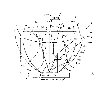
concentrator.
[0005] FIGS. 1-3 illustrate differences between a CPC and a parabolic
concentrator in general, as well as the operation of a CPC in receiving rays
of light over a
fairly large acceptance angle (1). Referring to FIG. 1, CPC 10 is formed from
two
parabolic mirrors. One arm 12 of CPC 10 is formed by cutting a parabola at
point 16 and
discarding the portion of the parabola shown in dashed line. The other arm 14
of CPC 10
is formed by cutting the parabola at point 18 and discarding the portion of
the parabola
shown in dashed line. The arms 12 and 14 are formed equal distance from
central axis 20,
and rotated about central axis 20 to form the symmetrical CPC reflective
surface.
[0006] Turning to FIG. 2, shown in cross section is a general
parabolic
concentrator 26 with reflective surface 22 rotated about central axis 24.
Comparing FIGS.
1-2, the entrance aperture of parabolic concentrator 26 is much larger than
that of CPC
10. However, as shown in FIG. 3, CPC 10 can receive light 28 at an acceptance
angle (I)
dissimilar from light that is perpendicular to the entrance aperture.
Accordingly, CPC 10
accepts a greater amount of light than other forms of concentrators, such as
the parabolic
concentrator.
[0007] Contrary to concentrators, illuminators send light outward as
opposed to
receiving light inward. Illuminators typically have a light source placed near
the base of a
secondary optical element. The light source forms a primary optical element in
that it
generates light, examples of which include incandescent lights or solid state
lights, such
as light emitting diodes (LEDs). LEDs are solid state devices that convert
electrical
energy to light, and generally comprise one or more active regions of
semiconductor
2
Date regue/Date received 2024-01-24
material interposed between oppositely doped semiconductor layers. Light is
emitted
from the active region and surfaces of the LED.
[0008] In order to generate a desired output color, it is sometimes
necessary to
mix colors of light using what is known as multi-color LED lights. Multi-color
LED light
can include one or more LEDs, which are mounted on a substrate and covered by
a
hemispherical silicon dome in a conventional package. The LEDs can emit blue,
red,
green, or other colors, and a combination of such can be mixed to produce any
desired
color spectrum.
[0009] Because of the physical arrangement of the various LED sources,
shadows
with color separation and poor color uniformity can exist at the output. For
example, a
source featuring blue and yellow may appear to have a blue tint when viewed
head on,
and a yellow tint when viewed from the side. Thus, one challenge associated
with multi-
color light LEDs is having good spatial and angular separation, otherwise
known as
spatial and angular uniformity projected outward in the near and far field of
the LED
source.
[0010] One method used to improve spatial and angular uniformity, and
thus
color mixing, is to reflect or refract light off several surfaces before it is
emitted. Color
mixing can also be achieved using a combination of reflection and refraction.
Both have
the effect of disassociating the emitted light from its initial emission
angle. Uniformity
typically improves, but each light interaction (reflection and refraction) has
an associated
loss.
[0011] FIG. 4 illustrates secondary optical elements used in
conjunction with the
primary optical element (LED source). The secondary optical elements of FIG. 4
solely
reflect light using either lens 30 or reflective housing 32. Both the
reflective housing 32
and lens 30 are used primarily to collimate the light output, as shown by the
collimated
output of rays 40 and 42. The LEDs, e.g., red, green, blue, and white, can be
spaced from
each other along a base plane to form array 34 further shown in FIG. 5. The
array of
LEDs extends in planar fashion along a base plane with cover 36 covering the
planar
arrangement of LEDs. Cover 36 may be mounted to the base, which is preferably
a
3
Date regue/Date received 2024-01-24
printed circuit board with a heat sink. LED array 34 is centered and
perpendicular to
central axis 38, which is preferably the central axis for reflector housing 32
and lens 30
being symmetrical about axis 38.
[0012] As shown in FIG. 4, lens 30 is a transparent lens made of
plastic or glass,
having a refractive index greater than air. As light beam 40 enters lens 30,
it enters at a
right angle to the convex spherical surface and reflects from the outer
surface in
collimated fashion outside of the lens. Thus, lens 30 is typically known as a
total inner
reflection (TIR) lens, with the angular outside surfaces made of a reflective
material in
the shape of a parabola rotated around central axis 38. The reflective portion
is
mathematically described as a parabola f(y) = ay2+ by + c, where y is the
height of the
lens from an entry to an exit.
[0013] Rays which do not enter the concave entry of lens 30 can be
reflected from
housing 32, such as ray 42. In either instance, FIG. 4 illustrates one example
of total
internal reflection using two reflective surfaces, one on the external surface
of lens 30
and the other on the external surface of housing 32. In either instance, only
a single light
interaction occurs, that being a reflection rather than refraction. Thus, no
matter where
LEDs 41 appear within, for example, a matrix with different colors of LEDs
spatially
positioned across the matrix, the output of the secondary optical element is
collimated
using a single light interaction.
[0014] Turning now to FIG. 6, lens 44 is shown. Lens 44 does not
require a
reflective housing or an air gap between a reflective housing and a TIR lens.
Lens 44 is
placed in close proximity to the LED array 34 so as to capture all light
emitted from the
LEDs, without need of a reflective housing. Lens 44 includes a spherical,
concave entry
surface 46 and a spherical, convex exit surface 48. In addition, exit portion
50 can be
made neither convex nor concave. The term convex is used to describe the
spherical
portions with convex being relative to the lens inner region and extending
inward toward
a center of the lens, while concave extends outward from the lens inner
portion. Both the
inward and outward extensions occur symmetrically about a central axis.
4
Date regue/Date received 2024-01-24
[0015] As shown in FIG. 6, any rays which extend from LED array 34 are
either
reflected 52 or refracted 54. Ray 52 reflects from the TIR outer surface of
lens 44,
whereas ray 54 refracts from convex surface 48. According to the law of
refraction, np
sine Op = na sine Oa. For example, using this equation and knowing that the
index of
refraction for air, na, is less than the index of refraction for plastic, np,
then Op < J. This
angular relationship is described in the angles Op and Oa shown in FIG. 6 to
indicate the
refraction and the change in angle from the perpendicular as ray 54 extends
from, for
example, plastic lens to air. In either case in which ray 52 is reflected or
ray 54 is
refracted, only one light interaction is needed for lens 44. Moreover, only
one light
interaction is needed to form a collimated output; thus, a collimation lens.
It is noted that
concave surface 46 is arranged so that whatever rays emit from LED array 34,
those rays
enter the concave surface 46 at substantially right angles; thus, no
refraction takes place
on the light entry region.
[0016] FIG. 7 illustrates lens 60 having a TIR surface symmetrical
around a
central axis. However, instead of the light entry region being concave, the
light entry
region 62 of lens 60 is convex. Moreover, there are straight sidewall surfaces
64 of equal
distance from the central axis, extending from the planar base on which LED
array 34 is
attached to convex surface 62. Thus, rays 66 are refracted on convex surface
62, whereas
rays 68 are refracted on the sidewall surface 64 and then reflected on the TIR
surface. No
more than one refraction occurs in either instance.
[0017] In addition to convex light entry surface 62, light exit
surface 70 can also
be convex as shown in dashed lines. Unfortunately, using a convex entry and
exit
surfaces causes light rays 72 to undergo two refractions, one on the entry and
another on
the exit. The second refraction at the exit may retain collimation, however,
angular
uniformity becomes a problem as the output projects at intensity peaks that
are spaced
from one another, and not evenly mixed across a plane perpendicular to the
central axis.
Moreover, two light interactions, both of which are refractive, significantly
impacts on
the output color spectrum as well as the output brightness itself. It is
typically important
to avoid refraction, since refraction can change the propagation path of the
emitted light
depending on the light wavelength. For example, a refracted beam that is blue
at the
Date regue/Date received 2024-01-24
source can take on a different propagation path through the lens than a light
beam that is
green. Thus, in settings that utilize, for example, red, green, blue, and
white LED sources,
it is generally desirable to avoid refraction, since refraction is typically
wavelength
dependent. It is also advantageous to avoid numerous light interactions,
including both
refraction and reflection. The more light interactions that occur, the output
lumen
brightness can deleteriously be affected.
[0018] In each of the lens structures described hereinabove,
collimation is
achieved at the projected output. However, pure collimation contains certain
drawbacks.
For example, the collimated output using two light interactions at shown in
FIG. 7 has an
inherent color mixing drawback. The output, while having intensity peaks, also
has
relatively poor angular uniformity. Each LED within the module 34 produces an
output
that extends outward in a radial angle approximately 180 degrees. For example,
a red
LED can be spaced from a green LED, and the output of each project their
angular output
a spaced distance from one another onto the two-light interactive lens which
then,
through refraction and/or reflection, collimates and projects the non-uniform
angular
output. The poor angular uniformity of the output will, unfortunately,
negatively impact
on color mixing. If improved color mixing is desired, pure collimation should
not be the
primary reason for selecting a lens. Moreover, color mixing can oftentimes
reduce the
output intensity and therefore having more than two light interactions is
problematic if
low power LED applications are all that are possible.
[0019] It would be desirable to achieve an improved lens design that
has
improved color mixing while selectively using a modified collimated output
from certain
portions of the lens design. Such a lens may require more than two light
interactions to
achieve not only better angular uniformity, and thus color mixing, but also
can be
implemented if the LED output can be appropriately increased. By using an
increased
LED output with at least three light interactions, it is further desirable to
collimate the
outer radial regions of the lens output while avoiding collimation on the
inner radial
regions of the lens output. Selectively tailoring collimation to the outer
region affords
more control through appropriately placed diffusion tunes that diffuse the
rays collimated
from the outer region to not only improve angular uniformity not available in
6
Date regue/Date received 2024-01-24
conventional lens designs but also to maintain improved color mixing across
the entire
output surface of the lens consistent with what is achieved in the inner
radial region.
[0020] Improved color mixing across the entire output surface is
achieved not
through collimation lenses as shown in FIGS. 4, 6 and 7, or derivatives
thereof, since
such lenses do not selectively control the lens output at the outer radial
region, nor do
they remove the concave or convex entry or exit surfaces at the inner radial
region that
cause poor angular uniformity, and thus poor color mixing of an LED output.
SUMMARY OF THE INVENTION
[0021] The problems outlined above are in large part solved by an
improved lens
having a straight entry at the inner radial region to improve color mixing of
LED output
near a central axis and at the detriment of collimation from that inner radial
region. The
improved lens also has a straight sidewall entry at the outer radial region to
improve color
mixing of LED output farther from the central axis even though such LED output
is
collimated. The straight sidewall entry is, however, configured with a surface
that
diffuses or scatters the light from the LED as it impinges upon a CPC
reflective output
surface and then to a concave spherical exit bounded by the CPC reflective
outer surface.
By configuring the non-collimated light exiting the inner radial region and
the collimated,
yet diffusion treated, light exiting the outer radial region, the outer
radially emitted light
surrounds the inner radially emitted light to make the projected light appear
in the near
and far field to be better color mixed across a broader angular range of the
LED output.
The lens, used as a secondary optical element, therefore achieves an improved
methodology for transferring color mixed light from one or more LEDs.
[0022] According to a first embodiment, a lens is provided for
receiving light
from an LED. The lens includes a cylindrical opening extending into the lens
from a light
entry region. The cylindrical opening is configured to receive the entirety of
light from
the LED. Across the entirety of a light exit region is a concave spherical
surface. The
concave spherical surface extends inward towards a central axis and is
symmetric about
that central axis. The arcuate path of the concave spherical surface extends
to the entire
7
Date regue/Date received 2024-01-24
outer surface near the light exit region. The outer surface is a TIR outer
surface shaped as
a CPC, which extends between the light entry region and the light exit region.
[0023] The cylindrical opening comprises a sidewall surface facing
toward and
equal distance foam a central axis. The sidewall surface receives light at the
outer radial
region, where light exits the LEDs more than, for example, 20 degrees from a
central axis
and which do not strike the straight, upper substantially circular plane that
is
perpendicular to the sidewall surface and forms the upper region of the
cylindrical
opening. Any light that strikes the upper substantially circular plane is
referred to as the
light at the inner radial region.
[00241 The sidewall surface preferably comprises a plurality of lunes,
each of
which is substantially planar having a length and width, the length being
greater than the
width and extending parallel to the central axis. The lunes are spaced equal
distance from
the central axis and terminate on the upper region of the cylindrical opening.
Depending
on the number of lunes, the upper plane becomes more circular as the number of
lunes
increases. The number of lunes is preferably between 8 and 20. If more than 20
lunes are
used, for a given lens dimension, more collimation can occur for radially
extending LED
light output, which is deleterious to the desired color mixing in the inner
radial region of
the lens. Less than 8 lunes would form more of a square upper plane causing a
greater
beam intensity loss than what can be achieved by simply increasing the LED
output.
[0025] The lens comprises a unibody construction and is of the same
material
contiguous throughout, with no seams, adjointments, or abutments of one body
to another
within the entirety of the lens, so that the lens is seamless and preferably
made from, for
example. a molding apparatus. The unibody material preferably has a refractive
index
greater than air, and is configured between surfaces formed by the sidewalls
of the
cylindrical opening, the concave spherical surface extending across the
entirety of the
light exit region, and the TIR outer surface shaped as a CPC.
[0026] According to another embodiment, an illumination device is
provided. The
illumination device comprises a unibody lens having a reflective outer surface
shaped as
a CPC around a central axis between an entry surface and a spherical concave
exit
8
Date regue/Date received 2024-01-24
surface. A plurality of LEDs are configured proximate to the entry surface and
spaced
from each other along a base plane perpendicular to the central axis. A
plurality of lunes
extends perpendicular from the base plane, each of the lunes having an
elongated planar
surface, wherein the elongated planar surface is configured an equal distance
along the
central axis to an upper plane that is parallel to the base plane. The upper
plan extends
radially outward from the central axis to a distal radius. Each of the
plurality of lunes
terminates at a 900 angle on the distal radius to form a cylindrical surface
bound by the
plurality of lunes, and the upper plane facing inward toward the base plane
and the LEDs.
[0027] The filling material of the unibody lens can be plastic or
glass, for
example. Such filling material can be injection molded acrylic,
polymethylmethacrylate
(PMMA), or any other faun of transparent material. The reflective surface of
the outer
TlR surface shaped as a CPC comprises any surface which reflects the light
rays coming
from the internal fill material, such as a square plate polyhedral reflective
surface.
[00281 According to all embodiments, the lens hereof purposely avoids
using any
housing reflector, but is implemented in a PAR form factor that provides
uniform color
throughout the standard 00, 25 , and upwards to 400 beam angles. The lens
preferably
has a pipe from the entry portion to the exit portion of no more than 1.4
inches, with the
spherical concave exit surface extending to the TIR reflector surfaces being
no more than
2.5 inches. The bottom diameter of the lens at the base plane is no more than
I inch.
Accordingly, the present lens is compact; thus, illustrating one benefit of
using a CPC
dimension rather than a standard parabolic dimension. The relatively small
form factor
that utilizes a compact design implemented through a CPC configuration
achieves not
only superior color mixing with improved, if not superior, brightness control,
but does so
using the unique lens configuration on both the entry and exit surfaces, and
further being
able to adjust the drive current supplied to the LED loads to accommodate any
changes in
wavelength-dependent refraction.
[0029] A methodology is provided to achieve these beneficial results
of
transferring light from an LED. The method includes transmitting a first
portion of the
light through air at a plurality of first angles relative to a central axis
around which the
9
Date regue/Date received 2024-01-24
lens is formed. Accordingly, the first portion of light, as well as a second
portion of light,
transmitted from the light source is typically Lanbertian, which means that
the LED
matrix or array of spaced LEDs emits light in all directions. However, the TIR
secondary
optical element extracts and collimates the light at the light exit surface.
The method
further comprises first refracting the first portion at a sidewall surface of
the light entry
surface. The refracted first portion of light is then reflected from an outer
surface of the
lens back into the lens, where a second refracting takes place. The second
refracting
refracts the reflected first portion from a spherical concave surface into the
air.
[00301 According to a further embodiment, the method comprises
transmitting a
second portion of light through air at a plurality of second angles relative
to the central
axis less than the plurality of first angles. A third refraction occurs
whereby the second
portion is again refracted at a planar surface perpendicular to the central
axis into the
lens. A fourth refraction occurs whereby the third refracted second portion is
again
refracted from the spherical concave surface into the air.
[0031] According to an alternative embodiment, a lens within an
illumination
device is provided that can achieve lessened glare output while maintaining
adequate
color mixing and beam control through the secondary optical element, or lens.
The
alternative lens configuration is one that implements a tapered cylindrical
opening, rather
than a cylindrical opening having a straight sidewall. The tapered sidewall of
the lens
inner radial region is proximate the light entry region, and can include a
diffusion treated
surface upon a first plurality of lunes to maintain sufficient beam control.
The diffusion
treated first plurality of tunes also provides appropriate color mixing.
[0032] Importantly, the concave spherical surface of the light exit
region does not
have any diffusion treatment on that surface. By avoiding any diffusion
treatment, or any
manufactured diffusion surface, the concave spherical surface of the light
exit region is
left clear and relatively smooth as a lens is taken from a smooth injection
mold device
surface. An exit surface that is not diffusion treated, or diffusion
manufactured through
texturing via etching, sandblasting, or by configuring a micro-lens array on
the surface,
the exit surface therefore beneficially reduces any glare output from the
illumination
Date regue/Date received 2024-01-24
device and through the lens. Eliminating any diffusion treatment, manufactured
diffusion,
or texturing on the entire concave spherical surface of the light exit region,
various forms
of direct and indirect glare are minimized.
[0033] Instead of placing diffusion treatment on the light exit region
of the
concave spherical surface, diffusion treatment or manufactured diffusion is
placed on a
surface of the lens entirely on the light entry region, and specifically on
the tapered
sidewall surface and the upper planar surface of the tapered cylindrical
opening. By
placing the diffusion at the light entry region and not at the light exit
region, glare is
minimized yet color mixing and beam control are maintained.
[00341 According to the alternative embodiment, the lens includes a
tapered
cylindrical opening having a tapered sidewall surface extending into the lens
from a light
entry region configured for receiving the entirety of light from one or more
LEDs. The
lens further includes a concave spherical surface extending across the
entirety of the light
exit region of the lens. Unlike the light entry region having the tapered
sidewall surface
and the upper planar surface that are diffusion treated or diffusion
manufactured, the
entirety of the concave spherical surface is neither diffusion treated,
diffusion
manufactured, or textured in any way. The lens further includes a TIR outer
surface
shaped as a CPC extending between the light entry region and the light exit
region.
[0035] The tapered cylindrical opening extends partially into the lens
from the
light entry region and is centered along a central axis of the lens. In order
to take on its
tapered shape, the tapered sidewall surface is configured about the central
axis a
decreasing radial distance from the central axis from the light entry region
toward the
light exit region. To form the taper, the decreasing radial distance is
approximately 4 -
relative to the central axis.
[0036] According to yet a further embodiment of the alternative
embodiment, the
tapered sidewall surface includes a plurality of planar lunes extending
radially inward
toward the central axis from the opening to the upper plane, with a
manufactured or
diffusion treated surface on each of the plurality of lunes. The plurality of
planar lunes
along the tapered sidewall surface are referred to as a first plurality of
lunes. A second
11
Date regue/Date received 2024-01-24
plurality of lunes exists on the TIR outer surface and are used to internally
reflect any
light entering the lens back out to the light exit region, and specifically
the concave
spherical surface of the lens. The second plurality of lunes assist in color
mixing while
collimating the light exiting the light exit region. The second plurality of
lunes extends
from the tapered cylindrical opening to the concave spherical surface at the
light exit
region, whereby the second plurality of lunes outnumber the first plurality of
lunes by a
ratio of between 1.5:1 to 2.5:1.
[0037] Further to the alternative embodiment, an illumination device
is provided.
The illumination device comprises a unibody lens having a reflective outer
surface
shaped as a CPC around a central axis between a diffusion manufactured light
entry
surface and a non-diffusion manufactured spherical concave light exit surface.
The
illumination device of the alternative embodiment further comprises at least
one LED, or
a plurality of LEDs, proximate to the light entry surface and spaced from each
other
along a base plane perpendicular to the central axis. The illumination device
according to
the alternative embodiment still further comprises a first plurality of lunes
upon the light
entry surface, each of the first plurality of tunes having an elongated planar
surface
extending a decreasing distance from the central axis from the base plane to
an upper
plane that is parallel to the base plane. A second plurality of tunes are
configured on the
reflective outer surface of a TIR lens shaped as a CPC, each having a second
elongated
planar surface extending an increasing distance from the central axis from the
base plane
to the spherical concave surface of the light exit region.
BRIEF DESCRIPTION OF THE DRAWINGS
[0038] Other objects and advantages of the invention will become
apparent upon
reading the following detailed description and upon reference to the
accompanying
drawings.
[0039] FIG. 1 is a plan view of a compound parabolic shape relative to
a
parabolic shape;
12
Date regue/Date received 2024-01-24
[0040] FIG. 2 is a plan view of a parabolic shape having a wider
radius from a
central axis than the compound parabolic shape;
[0041] FIG. 3 is a plan view of a compound parabolic concentrator
typically used
to accept and concentrate solar rays onto a focal point;
[0042] FIG. 4 is a side cross sectional view of a lens mounted within
a reflective
housing to achieve total internal reflection;
[0043] FIG. 5 is a view along plane 5 of FIG. 4 showing an array of
LEDs;
[0044] FIG. 6 is a side cross sectional view of a TIR lens absent a
reflective
housing to achieve total internal reflection using only one light interaction;
[0045] FIG. 7 is a side cross sectional view of a TIR lens absent a
reflective
housing to achieve total internal reflecting using no more than two light
interactions;
[0046] FIG. 8A is a side cross sectional view a lens with a TIR outer
surface
shaped as a CPC and having up to three light interactions to achieve improved
output
collimation and color mixing according to one embodiment of the present
invention;
[0047] FIG. 8B is a blow up cross sectional view of the diffusion
surfaces;
[0048] FIG. 9A is a view along plane 9-9 of FIG. 8A showing a
cylindrical
opening having a plurality of luncs arranged along the sidewall surface of the
cylindrical
opening.
[0049] FIG. 9B is a blow up cross sectional view of the two lunes of a
TIR lens
shaped with a CPC;
[0050] FIG. 10A is a side cross sectional view of the lens of FIG. 8A
according to
an alternative embodiment in which the concave light exit region does not
comprise a
diffusion surface and the light entry region comprises diffusion surfaces and
a tapered
sidewall surface to minimize glare;
13
Date regue/Date received 2024-01-24
[0051] FIG. 10B is a blow up cross sectional view of the diffusion
surfaces
configured on the light entry region of the lens according to the embodiment
of FIG.
10A; and
[0052] FIG. 11 is a cross-section view along plane 11 of FIG. 10A
showing the
reflective TIR outer surface of the lens having a plurality of lunes, each
having a width
that extends around the circumference of the outer surface and a length
extending from
the light entry region to the light exit region.
DETAILED DESCRIPTION OF THE PREFERRED EMBODIMENTS
[0053] FIG. 8A illustrates lens 80 filled with material 82, e.g., an
injection
molded light transparent material. Material 82 is bound between light entry
region 84,
light exit region 86, and TIR outer surface 88, which is shaped as a CPC. TIR
outer
surface 88 has a smaller exit region then a parabolic TIR, shown in dashed
line 90.
Moreover, exit region 86 comprises concave spherical surface 94, instead of
most
conventional parabolic lenses having a flat surface, shown in dashed line 96.
Thus, FIG.
8A illustrates a comparison between a conventional parabolic lens 91 and the
present lens
80. Present lens 80 is not only shaped as a CPC, but also is more compact in
its
configuration, being less than 2.5 inches in diameter for exit region 86, 1
inch in diameter
for entry region 84, and no more than 1.4 inches in height from the entry
region to the
exit region. The entry region is defined as a planar base on which the LEDs
100 reside.
The overall maximum height of the compact PAR dimension of the present
invention is
1.4 inches from the planar base to the outer extents of the TIR reflective
surface 88 at
which it joins the concave spherical surface 94.
[0054] Of import, the compact PAR configuration of lens 80, which is
shaped as
a CPC, is beneficial over the conventional parabolic lens. Conventional lens
91 can
receive light passing through a sidewall surface 102 near the light entry
region 84, such
sidewall surface constitutes the sidewall surface of a cylindrical opening,
also having an
upper planar surface 104. The dashed line indicates refraction at angles
4:130pA1 and olopm2 at
the plastic-to-air interface of the parabolic lens. Next, a reflection occurs
at the TIR
external surface of lens 91, shown at angles OR; and (I)R4, whereby the
reflected light is
14
Date regue/Date received 2024-01-24
then refracted at the exit surface of lens 91 by the interaction of Opm2 to
OpA2. The
resulting exiting light ray or beam may not be collimated. Thus, it is
desirable to form a
collimated lens, which can be achieved by strict adherence to the
configuration of lens
80, with a cylindrical opening that forms sidewall surface 102 and upper
planar surface
104, along with concave spherical surface 94, where surface 94 must extend
across the
entirety of the light exit region from the central axis about which lens 80 is
symmetrical
to external surface 88.
[0055] FIG. 8A illustrates that any beam that strikes sidewall surface
102 must go
through three light interactions. For example, beam 106 goes through a
refraction
(1)A1ADm1 at sidewall surface 102 to a reflection (1)}01)R2, to another
refraction 4N2/0A2 on
surface 94. Beam 108 also goes through three interactions. The first
interaction is a
refraction, followed by a reflection, ending with another refraction. Thus,
every beam that
enters the sidewall surface near the beam entry portion goes through the
sequence of
refraction, reflection, and refraction, finally exiting the light exit region
as a collimated
light beam, which is not achievable in conventional lens 91. For brevity and
clarity of the
drawings in showing the various ray paths, which can exceed several hundred if
not
thousands, only two are shown for lens 80 entering the sidewall surfaces.
Moreover, so as
not to obscure the ray path line, material 82 is not shown in cross-hatch;
however, it is
understood that in the region between the cylindrical opening near the light
entry region
to the concave spherical surface of the light exit region, lens 80 is filled
with unibody
material 82, which is contiguous and non-interrupted, such as injection
molding.
[0056] In addition to transmitting a first portion of light from LEDs
100 through
air attributable to the cylindrical opening where it impinges upon sidewall
surface 102, a
second portion of light can be sent through air of the cylindrical opening
where it
impinges upon planar upper surface 104. The first portion of light is first
refracted at
surface 102, then reflected at surface 88, then second refracted at surface
94. The second
portion of light 110 is third refracted (1)A3/(1)m3, if it impinges upon the
planar upper
surface at a non-perpendicular angle, where it is later fourth refracted
(1)1\44/0m on surface
94.
Date regue/Date received 2024-01-24
[0057] The first portion of light from the outer radial region of the
LED output is
shown collimated as it exists as beam 106. The first portion, however, passes
through
diffusion surfaces on the sidewall surface 102 to scatter, or mix the light
output to
achieve both angular and linear uniformity of the output. Such diffused,
collimated output
is purposely placed on the outer radial region to surround the non-collimated
inner radial
region of the LED output to achieve color mixing at the near and far field.
The improved
color mixing is due to the unique configuration of the cylindrical opening of
the light
entry region to the concave spherical surface of the light exit region, bound
by a
reflective outer surface being CPC-shaped to achieve an overall compact
dimension of a
PAR lamp.
[0058] On sidewall surface 102, planar upper surface 104, and exit
surface 94 of
lens 80 is a diffuser surface 112, shown in FIG. 8B. Diffuser surface 112
scatters light
from the various LED sources, resulting in a wider beam angle. In general,
diffuser
surface 112 is preferably configured with some combination of differently
textured
surfaces and/or patterns 114, so that light 116 entering the surface will get
scattered or
diffused, shown by light 118. For example, lensets that perform the scattering
can be
rectangular or square shaped domes, and may be small enough so that the
curvature of the
lensets is defined by the radius of the arcs that create the lensets.
[0059] FIG. 9A illustrates a plurality of lunes 120, when viewed from
the base of
lens 80 along plane 9-9 of FIG. 8A. Peering into the cylindrical opening, a
series of
substantially flat or planar lunes 120 extend along sidewall surface 102
spaced equal
distance from central axis 122. Shown are eight lunes, and preferably, the
improved lens
design hereof uses between eight to no more than 20 lunes to enhance color
mixing in the
inner cylindrical opening into which the LED output enters. Each lune has an
elongated
surface that extends the entire length of the sidewall surface from the planar
base on
which LEDs 100 reside to upper planar surface 104. The elongated surface of
lunes 120
extend perpendicular from the base plane, spaced equal distance along central
axis 122 to
upper plane 104 that is parallel to the base plane. The lunes are simply
planar cutouts
from lens 80, formed as part of the injection molding process when the fill
material is
16
Date regue/Date received 2024-01-24
applied to the mold, with the mold outer regions within the cylindrical
opening of the lens
having a plurality of circumferentially configured planar surfaces.
[0060] FIG. 9B is an expanded view of a region showing two lunes
120a/120b,
and provides a general description as to why such surfaces are defined as
lunes. The lune
surfaces are formed as a concave-convex area, shown in cross hatch, bounded by
two
circular arcs. The June surfaces 120a/120b are formed therefrom.
[0061] Turning now to FIGS. 10A, 10B and 11, an alternative embodiment
for a
lens is shown. Contrary to the lens shown in FIGS. 8A and 8B, the lens in
FIGS. 10A and
10B is a lens that emits a lower glare from the light exit region 86, and
specifically the
concave spherical surface 94 that extends across the entirety of the light
exit region 86.
Since lens 80 shown in FIG. 10A is one having a TlR outer surface and shaped
as a CPC,
many like numerical identifiers exist between FIG. 10A and FIG. 8A describing
a TIR
lens 80, albeit some of the surfaces of lens 80 in FIG. 10A are different from
the surfaces
of lens 80 in FIG. 8A.
[0062] For example, the concave spherical surface 94 of the light exit
region 86 in
the alternative embodiment shown in FIG. 10A does not have any diffusion
treatment or
any diffusion manufactured thereon. Accordingly, FIG. 10B shows a diffusion
surface of
textured patterns 114 so that light 116 entering the surface will get
scattered or diffused,
shown by light 118. Importantly, diffuser surface 112 exists only on the light
entry
region, and specifically on the tapered sidewall surface 102 and the upper
planar surface
104. While similar numerals are shown for the sidewall surface 102 and the
upper planar
surface 104 of the cylindrical opening, the alternative embodiment of FIG. 10A
indicates
nonetheless a difference from the sidewall surface 102 and the upper planar
surface 104
in FIG. 8A. Specifically, the sidewall surface 102 in FIG. 10A is tapered and
not
perpendicular to the base plane on which the LEDs 100 extend, while the
sidewall
surface 102 in FIG. 8A is a straight sidewall surface that is perpendicular to
the base
plane on which the LEDs 100 extend. More diffusion or texture can be applied
to the
tapered sidewall surface 102 than to the straight sidewall surface 102.
17
Date regue/Date received 2024-01-24
[0063] FIGS. 10A and 10B do not illustrate any diffuser surface on the
light exit
region 86, and specifically the concave spherical surface 94 of the light exit
region 86.
All diffusion is placed on the tapered sidewall surface 102 and the upper
planar surface
104, of the light entry region. By placing the diffuser surface only on the
light entry
region, and tapering the sidewall of the tapered cylindrical opening, color
mixing can be
maintained somewhat close to that of the embodiment shown in FIG. 8A. However,
by
removing any diffuser surface from the light exit region, a lower glare can be
achieved.
[0064] It is typically recognized that there are at least two types of
glare: direct or
indirect. Direct glare is the glare that appears when a person looks straight
onto the
illumination device source, or the LED behind the secondary optic lens.
Indirect glare is
that which occurs from illumination output reflected off surfaces in the field
of view.
Those surfaces can be within the lens itself or outside the lens, such as on
an object distal
from the illumination device (e.g., a desk, computer screen, etc.).
[0065] Regardless of the type of glare, glare in general can cause
significant
problems such as blurred images, eye strain, or even headaches. Typical ways
in which to
deal with glare and the visual discomforts associated therewith, are anti-
glare structures.
Popular anti-glare structures include diffusive films and reflective screens.
Anti-glare
structures are oftentimes placed on the illumination device in an attempt to
match and
offset any reflection that might arise from the illumination output. It is
difficult at best to
perform such matching and, if done successfully results in a complicated
design and
manufacturing of the matching and offsetting screens that almost certainly
results in poor
light efficiency output from the illumination device.
[0066] The problems of glare and any failed attempts to offset that
glare by anti-
glare reflective filtering, screening, etc. are eliminated entirely by
ensuring that no such
anti-glare screening, filtering or offsetting occurs on the light exit region.
Such problems
are therefore solved by removing any diffusive surface from the concave
spherical
surface 94 and instead tapering the sidewall surface 102 to effectuate
diffusion closer to
the light source, or LEDs 100. This allows the natural refraction and
reflection within the
18
Date regue/Date received 2024-01-24
lens to cause any necessary offset or matching to occur within the lens and
not to add any
additional glare by attempting a diffusive surface on the light exit region
86.
[0067] Minimizing glare in ceiling-mounted light fixtures, and
specifically PAR
downlights that use LEDs not only eliminates glare zones, but according to the
anti-glare
alternative embodiment shown in FIGS. 10A-11, no offset, reverse compensation,
glare-
tuning, matching, or any other expensive and difficult to manufacture exit
diffuser
surfaces are needed on the concave spherical surface 94 of the exit region 86.
All glare
control and glare-zone elimination occurs at the light entry region, and
specifically
through use of a tapered cylindrical opening and the various refraction and
reflections
that occur within the CPC shape itself.
[0068] As shown in FIG. 10A, LEDs 100 are moved closer to the upper
planar
surface 104, as shown in dashed line, and the opening 130 of the tapered
cylindrical
opening can be made of a larger diameter, possibly more than one inch so that
the
diameter of the concave spherical surface 94 relative to the central axis 132
is between 2-
2.5 times the diameter of the opening 130, also relative to the central axis
132.
Accordingly, if the diameter of opening 130 is greater than one inch, and the
diameter of
the concave spherical surface 94 diameter is 2.5 inches, the ratio would be
less than 2.5.
The amount of taper of the sidewall surface 102 can be described as an angle
4) relative to
the central axis 132. Accordingly, angle 4) of the tapered sidewall surface
relative to the
central axis 132 can range between 40 to 10 . The amount of taper is primarily
determined by the specific beam angle requirement. Also, the amount of
diffusion
manufactured on the tapered sidewall surface 102 and the upper planar surface
104 of the
light entry region is dependent upon the amount of color mixing and beam
uniformity
needed.
[0069] Like the embodiment shown in FIGS. 8A-9B, the low glare
embodiment
shown in FIGS. 10A-11 also include a first plurality of lunes on the sidewall
surface 102.
The only difference between the two different embodiments is that the lunes on
the
sidewall surface 102 in FIG. 10A are tapered planar surfaces and the first
plurality of
lunes on the embodiment in FIG. 8A are not tapered and extend perpendicular to
the base
19
Date regue/Date received 2024-01-24
plane. Specifically, the tapered first plurality of planar lunes extend as
part of the tapered
sidewall surface radially inward toward the central axis from the opening 130
to the
upper plane 104. All of the first plurality of lunes are of equal length and
all of the first
plurality of planar lunes are ones that extend from the opening to the upper
plane. Each of
the first plurality of tapered lunes has a manufactured diffusion surface
thereon.
[0070] While the TIR reflective surface in the embodiment of FIG. 8A,
shown as
numeral 88 does not have a second plurality of planar lunes, the embodiment in
FIGS.
10A-11 for low glare configuration does. As shown in the cross-section 11-11
of the
outer reflective surface 88 in the second embodiment, a second plurality of
planar lunes
140 are arranged upon the reflective outer surface 88. Each of the second
plurality of
lunes 140 has a second elongated planar surface extending an increasing
distance from
the central axis 132 from the opening 130 of the base plane on which LEDs 100
exist to
the spherical concave exit surface 94. Each of the second plurality of lunes
are compound
parabolic in shape to conform to the CPC outer surface, yet having a planar
shape bent as
it extends from the light entry region to the light exit region. Preferably.
the ratio between
the number of second plurality of lunes and the number of first plurality of
lunes is
between 1.5:1 and 2.5:1. Thus, if the first plurality of lunes is between 8
and 20, the
second plurality of lunes is between 12-50. As shown in FIG. 11, the second
plurality of
tunes 140 preferably exists on the inside surface of the outer reflective
surface 88. The
second plurality of lunes 140, are therefore reflective planar surfaces that
reflect all light
that are received on the lunes back into the lens 80 and out through the light
exit surface
86. The second plurality of lunes therefore achieves TIR functionality, but
within a CPC
configuration.
[0071] It will be appreciated to those skilled in the art having the
benefit of this
disclosure that this invention is believed to provide an improved lens
configuration that
achieves improved color mixing. The improved color mixing occurs by treating a
collimated outer radial region of the LED module output, while maintaining non-
collimation on an inner radial region of the LED output. More than three light
interactions are needed to achieve the improved color mixing, with both
improved spatial
and angular uniformity. Improved glare control is also achieved using a taped
diffusion-
Date regue/Date received 2024-01-24
manufactured sidewall surface of a light entry region without any diffusion
manufactured
on the concave spherical surface of the light exit region. Further
modifications and
alternative embodiments of various aspects of the invention will be apparent
to those
skilled in the art in view of this description. It is intended that the
following claims be
interpreted to embrace all such modifications and changes. Accordingly, the
specification
and drawings are to be regarded in an illustrative, rather than a restrictive,
sense.
21
Date regue/Date received 2024-01-24