Note: Descriptions are shown in the official language in which they were submitted.
WO 2023/023145
PCT/US2022/040585
THREADED FASTENER
RELATED APPLICATIONS
100011 This application claims priority to U.S. Patent
Application No. 17/406,000,
filed on August 18, 2021, the disclosure of which is incorporated herein by
reference in its
entirety.
BACKGROUND
100021 A nut is a piece of hardware that may be threaded onto
an axle or spindle to
secure a wheel. When installing, the correct torque should be applied to the
nut to maximize
bearing life and to ensure that the axle nut will not loosen over time.
SUMMARY
100031 The present embodiments include a threaded fastener
that may be used in
any application that uses nuts and similar types of threaded fasteners. For
example, the threaded
fastener may be used as an axle nut to secure components on a threaded
spindle.
Advantageously, the threaded fastener may be constructed using readily
available commercial
components, and can easily lock into place to prevent movement of a wheel
bearing. The
threaded fastener is easily removable for service and unitized (i.e., has
components that are
physically connected to form a single part) to prevent components from
separating and to
prevent tampering with the threaded fastener, wheel bearing, or both.
100041 In embodiments, a threaded fastener includes a nut
forming a threaded center
hole that defines a rotational axis of the threaded fastener. The threaded
fastener also includes
a plurality of spring plungers affixed to the nut, each having a shaft that is
aligned parallel to
the rotational axis. The threaded fastener also includes a positioner forming
(i) an unthreaded
center hole that is coaxial with the threaded center hole and (ii) a plurality
of recesses facing
the plurality of spring plungers. At least one of the plurality of spring
plungers engages with a
corresponding at least one of the plurality of recesses when the nut is
tightened against the
positioner on a threaded spindle.
BRIEF DESCRIPTION OF THE DRAWINGS
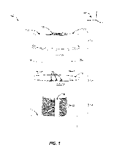
100051 FIG. 1 is an exploded view of a threaded fastener that
affixes to a threaded
spindle, in an embodiment.
1
CA 03227571 2024- 1- 31
WO 2023/023145
PCT/US2022/040585
[0006] FIG. 2 is a perspective view of a positioner of the
threaded fastener of FIG. 1,
in an embodiment.
[0007] FIG. 3 is a cross-sectional view of the threaded
fastener of FIG. 1 showing a
contact engaged with a recess, in an embodiment.
[0008] FIG. 4 is a cross-sectional view of the threaded
fastener of FIG. 1 showing
the contact not engaged with the recess.
100091 FIG. 5 is a side cutaway view of the threaded fastener
of FIG. 1, in an
embodiment.
[0010] FIG. 6 is a top view of the threaded fastener of FIG.
1 illustrating azimuthal
positioning of plungers about a rotation axis, in an embodiment.
[0011] FIG. 7 is a cross-sectional view of the threaded
fastener of FIG. 1 showing
an indentation cooperating with a retaining ring to axially constrain the
positioner, in an
embodiment.
[0012] FIG. 8 is a cross-sectional view showing the threaded
fastener of FIG. 1 with
another embodiment of the retaining ring.
[0013] FIG. 9 is a cutaway view of a threaded fastener that
is similar to the threaded
fastener of FIG. 1 except that it uses a positioner shaped as an undulating
wire to create a
plurality of recesses, in an embodiment.
100141 FIG. 10 shows the positioner of FIG. 9 in more detail,
in an embodiment.
[0015] FIG. 11 is a side cutaway view of the threaded
fastener of FIG. 9 that
illustrates a circumferential gap in more detail, in an embodiment.
DETAILED DESCRIPTION
[0016] FIG. 1 is an exploded view of a threaded fastener 100
that affixes to a
threaded spindle 108. The threaded fastener 100 includes a nut 102 forming a
threaded central
hole 122 that is threaded to match external threads 126 of the spindle 108.
The threaded central
hole 122 and spindle 108 are coaxial to a rotation axis 124 about which the
nut 102 rotates, and
along which the nut 102 linearly translates, or advances, to engage with the
external threads 126
of the spindle 108. For clarity herein, it is assumed that the rotation axis
124 coincides with the
z axis of a right-handed Cartesian coordinate system 120, wherein the nut 102
translates in the
-z direction when engaging with the spindle 108, and in the +z direction when
disengaging from
the spindle 108.
100171 FIG. 2 is a perspective view of a positioner 104 of
the threaded fastener 100.
The positioner 104 is shaped as a disc 148 that lies flat in the x-y plane and
forms an unthreaded
2
CA 03227571 2024- 1- 31
WO 2023/023145
PCT/US2022/040585
central hole 134 through which the spindle 108 passes. The disc 148 also forms
a sequence of
recesses 114 located circumferentially around the unthreaded central hole 134.
Extending
axially upward (i.e., along the +z direction) from an outer edge of the disc
148 is a lip 146. As
described in more detail below, the lip 146 forms a plurality of indentations
138 that can be
pushed radially inward to unitize the threaded fastener 100.
100181 In some embodiments, the disc 148 forms a tab 136 that
extends radially
inward to engage with a vertical slot 118 formed by the spindle 108. The tab
136 and slot 118
cooperatively prevent the positioner 104 from rotating about the rotation axis
124. It is assumed
herein that the slot 118 is located in the +y direction relative the rotation
axis 124. Thus, when
the positioner 104 is engaged with the spindle 108, the tab 136 will be
located in the slot 118,
and therefore also located in the +y direction relative to the rotation axis
124.
100191 Affixed to the nut 102 circumferentially around the
threaded central hole 122
are a plurality of spring plungers 106 that engage with the recesses 114. The
plungers 106
cooperate with the recesses 114 to create a detent mechanism that both arrests
motion of the nut
102 while it is being tightened onto the spindle 108 and divides rotation of
the nut 102 into
discrete angular increments about the rotation axis 124. In FIG. 1, the nut
102 forms a first
plunger mounting hole 112(1) and a second plunger mounting hole 112(2) that
receive the first
plunger 106(1) and the second plunger 106(2), respectively. However, the
threaded fastener 100
may have only one plunger 106, or more than two plungers 106 (and
corresponding plunger
mounting holes 112) without departing from the scope hereof
100201 As shown in FIG. 1, the nut 102 may be transversely
(i.e., in the x-y plane)
shaped as a truncated hexagon (i.e., a hexagon with each of its corners
truncated to form an
irregular twelve-sided polygon). Alternatively, the nut 102 may be
transversely shaped as an
untruncated regular hexagon, or another kind of regular or irregular polygon.
Each of the spring
plungers 106 may be positioned near a corner of the polygon, where there is
generally more
material to form a plunger mounting hole 112, as compared to regions away from
the corners.
100211 One advantage of the threaded fastener 100 is that all
of the plunger
mounting holes 112 can be drilled into one axial end of the nut 102. Thus, the
nut 102 only
needs to be mounted one time to a fixture (e.g., a vise) for drilling all of
the plunger mounting
holes 112. Alternatively, the nut 102 can be made from a process such as metal
injection
molding (M11\4). Since the plunger mounting holes 112 have axes that are
parallel to each other
(and parallel to the rotation axis 124), the nut 102 can be pulled off of the
MEW tooling in a
single direction, drastically reducing manufacturing complexity. By contrast,
plunger mounting
holes drilled radially through the nut 102 would require the nut 102 to be
rotated and remounted
3
CA 03227571 2024- 1- 31
WO 2023/023145
PCT/US2022/040585
for each hole. Similarly, all of the recesses 114 can be advantageously
drilled into one side of
the disc 148 of the positioner 104.
100221 FIGS. 3 and 4 are cross-sectional views of the
fastener 100 when threaded
onto the spindle 108. FIGS. 3 and 4 depict operation of the fastener 100 after
it has been
advanced along the spindle 108 such that the positioner 104 contacts an end
face 110 of the
spindle 108, i.e., the axial position of the positioner 104 is fixed by the
end face 110. A bottom
face 232 of the nut 102 is axially separated (i.e., along the z direction)
from a top face 234 of
the positioner 104 by a gap 244. The nut 102 may be torqued (e.g., by a
wrench) to either tighten
or loosen the fastener 100. When the fastener 100 is tightened, the nut 102
advances toward the
positioner 104 (i.e., in the -z direction), thereby reducing the gap 244. The
fastener 100 may be
tightened to a predetermined torque level (e.g., by a torque wrench) or such
that it "bottoms
out" when the bottom face 232 directly contacts the top face 234. Conversely,
when the fastener
100 is loosened, the nut 102 advances away from the positioner 104 (i.e., in
the +z direction),
thereby increasing the gap 244. For clarity, the wrench used to torque the nut
102 is not shown
in FIGS. 3 and 4. FIGS. 3 and 4 are best viewed together with the following
description.
100231 The cross-sectional views of FIGS. 3 and 4 are taken
through the rotation
axis 124 and a plunger 206 which may be any one of the plungers 106 in FIG. 1.
The plunger
206 has a cylindrical shaft 216 with a plunger axis 226 that is parallel to
the rotation axis 124
and transversely displaced from the rotation axis 124 (i.e., in the x-y plane)
by a radial distance
R. The plunger 206 is inserted into a plunger mounting hole 212 which may be
any one of the
plunger mounting holes 112 in FIG. 1. The plunger mounting hole 212 may be a
straight
unthreaded through-hole or blind hole into which the plunger 106 is inserted
and affixed via an
interference fit. Alternatively, the plunger 106 may be inserted into the
plunger mounting hole
212 and affixed thereto via epoxy. Alternatively, the plunger mounting hole
212 may be
threaded to accept external threads of the cylindrical shaft 216, in which
case the plunger 206
is threaded into the plunger mounting hole 212. The plunger 106 may inserted
into, and affixed
to, the plunger mounting hole 212 using another mounting mechanism without
departing from
the scope hereof
100241 The plunger 206 also has a contact 218 affixed to the
bottom of a spring 228
that extends and compresses along the plunger axis (i.e., the z direction).
The top of the spring
228 is fixed to the shaft 216, and therefore the spring 228 exerts an axial
force against the
contact 218, thereby pushing the contact 218 downward. The contact 218 is
shaped to engage
with each of the recesses 114 when positioned thereover. For example, in FIGS.
3 and 4 the
contact 218 is shaped as a sphere (e.g., a ball bearing). Alternatively, the
contact 218 may be a
4
CA 03227571 2024- 1- 31
WO 2023/023145
PCT/US2022/040585
pin with a curved bottom face (e.g., a bullnose). Without departing from the
scope hereof the
contact 218 may be another type of mechanism that is actuated via the spring
228 to engage
with the recesses 114.
100251 FIG. 3 shows the contact 218 engaged with a recess
214, which may be any
one of the recesses 114 of FIGS. 1 and 2. In FIG. 3, the contact 218 extends
downward (i.e., in
the negative z direction) below the top face 234 of the positioner 104 to at
least partially enter
the recess 214. In the example of FIG. 3, the recess 214 is a countersunk hole
formed downward
from the top face 234 and shaped as an inverted truncated right circular cone.
The countersink
angle, or apex angle, of the cone may be 82 , 90 , 100 , or another value
between 00 and 180 .
While FIG. 3 shows the recess 214 as a through hole, the recess 214 may
alternatively be a
blind hole. In this case, the recess 214 may be shaped as an untruncated right
circular cone.
Alternatively, the recess 214 may be a straight through hole or blind hole, or
a counterbored
hole. However, the recess 214 may have a different shape than shown herein and
need not be
cylindrical or conical.
100261 FIG. 4 shows the contact 218 not engaged with the
recess 214. In this case,
the spring 228 exerts an axially downward force that pushes the contact 218
directly against the
top face 234 of the positioner 104. As compared to FIG. 3, the spring 228 in
FIG. 4 is more
compressed, and therefore exerts a greater downward force on the contact 218.
Once the
positioner 104 contacts the end face 110 of the threaded spindle 108, and the
nut 102 is further
torqued about the rotation axis 124, the contact 218 will slide across the top
face 234 until it
encounters, and extends downward to enter, the next recess of the sequence.
100271 As shown in FIGS. 3 and 4, the plunger mounting hole
212 may form a
counterbore extending upward from the bottom face 232 of the nut 102 to create
an internal
shoulder 230. A depth of the counterbore in the +z direction may be selected
to accommodate
a flange 236 of the plunger 206 that, when pushed upwards against the shoulder
230, establishes
the vertical position of the plunger 206, and thus the contact 218, relative
to the bottom face
232. However, another mechanism may be used to vertically position the plunger
206 without
departing from the scope hereof For example, if the plunger mounting hole 212
is a blind hole
formed upward from the bottom face 232, then the depth of this blind hole may
be selected to
vertically locate the plunger 206, and thus the contact 218, relative to the
bottom face 232.
100281 FIG. 5 is a side cutaway view of the threaded fastener
100 of FIG. 1. For
clarity in FIG. 5, the spindle 108 is not shown, thereby showing internal
threads of the threaded
central hole 122. In FIG. 5, the first plunger 106(1) is engaged with a first
recess 114(1) while
the second plunger 106(2) is not engaged with any of the recesses 114. Thus,
in this embodiment
CA 03227571 2024- 1- 31
WO 2023/023145
PCT/US2022/040585
the recesses 114 and plungers 106(1) and 106(2) are positioned azimuthally
about the rotation
axis 124 such that only one of the plungers 106(1) and 106(2), at most, is
engaged with one of
the recesses 114, regardless of the rotational angle of the nut 102.
100291 FIG. 6 is a top view of the threaded fastener 100 of
FIG. 1 illustrating
azimuthal positioning of the plungers 106(1) and 106(2) about the rotation
axis 124. In FIG. 6,
the center of the first plunger mounting hole 112(1) is defined by a first
radial vector 'Pi lying
in the transverse x-y plane with the rotation axis 124 as the origin.
Similarly, the center of the
second plunger mounting hole 112(2) is defined by a second radial vector f-'2.
Both of the plunger
mounting holes 112(1) and 112(2) are centered at the radial distance R from
the rotation axis
124, i.e., II = I2I = R. However, the azimuthal angle 0 in the transverse x-y
plane between
the radial vectors f'-'1 and f22 is not 180 . Specifically, the first plunger
mounting hole 112(1) is
centered over one of the recesses 114 such the first plunger 106(1) will
engage with said one of
the recesses 114. However, the second plunger mounting hole 112(2) is located
between two of
the recesses 114 such that the second plunger 106(2) will not engage with any
of the recesses
114. Thus, the plunger mounting holes 112(1) and 112(2) are azimuthally
positioned about the
rotation axis 124 such that only one of the plungers 106(1) and 106(2), at
most, engages with
one of the recesses 114.
100301 The positioner 104 forms N recesses 114 that are
uniformly spaced about the
rotation axis 124 by a recess angular increment 41) = 360 /N. Thus, the
recesses 114 have a N-
fol d rotational symmetry about the rotation axis 124. In the example of FIG.
6, N = 32, and
therefore the recess angular increment is ck = 360 /32 = 11.25 . However, N
may be a different
value without departing from the scope hereof In FIG. 6, the second plunger
mounting hole
112(2) is located halfway between two of the recesses 114. As the nut 102
rotates about the
rotation axis 124, the plungers 106(1) and 106(2) alternatingly engage with
the recesses 114 to
produce a series of audible "clicks". The first plunger 106(1) produces one
click when the nut
102 is rotated by 41). The second plunger 106(2) also produces one click when
the nut 102 is
rotated by 41). However, the clicks generated by the plungers 106(1) and
106(2) will be
interleaved such that rotation of the nut 102 by 0/2 produces one click. Thus,
FIG. 6 shows
how two plungers 106 can be used to produce clicks at one-half the angular
increment 0. This
concept may be extended to more than two plungers 106 to produce clicks at
even smaller
fractions of the angular increment (/). For example, when the threaded
fastener 100 has three
plungers 106, these three plungers 106 may be azimuthally positioned such that
rotation of the
nut 102 by 0/3 produces one click. More generally, when the threaded fastener
100 includes p
6
CA 03227571 2024- 1- 31
WO 2023/023145
PCT/US2022/040585
plungers 106, where p is any integer greater than or equal to 1, the p
plungers 106 may be
azimuthally positioned such that rotation of the nut 102 by (/)/p produces one
click.
[0031] In the example of FIG. 6, the azimuthal angle 0 is
174.375 . However, the
plunger mounting holes 112(1) and 112(2) may be alternatively positioned to
form a different
azimuthal angle 0 such that the second plunger 106(2) is positioned between a
different pair of
neighboring recesses 114 when the first plunger 106(1) engages with one of the
recesses 114.
In another embodiment, the azimuthal angle 0 is 1800 and the number of
recesses 114 is odd.
In this case, no two of the recesses 114 are azimuthally separated by 180 ,
thereby ensuring that
the plungers 106(1) and 106(2) do not simultaneously engage with two of the
recesses 114.
[0032] In other embodiments, the threaded fastener 100
includes a plurality of
plungers 106 that are uniformly spaced, azimuthally about the rotation axis
124, by a plunger
angular spacing. The plurality of recesses 114 may also be uniformly spaced,
azimuthally about
the rotation axis 124, by a recess angular spacing. When the plunger angular
spacing is not an
integer multiple of the recess angular spacing, only one of the more than two
plungers 106, at
most, will engage with one of the recesses 114 as the nut 102 rotates. This
condition is
equivalent to the number of recesses 114 not being an integer multiple of the
number of plungers
106.
[0033] Those skilled in the art will recognize that the
torque needed to disengage a
plunger 106 from a recess 114 will quantitatively depend on the size and
geometry of each
recess 114 (e.g., the diameter, depth, and countersink angle), the size and
geometry of each
contact 218 (e.g., the diameter of the sphere ball bearing), the radial
distance R, and the spring
constant of each spring 228. Accordingly, one or more of these parameters may
be selected to
achieve a predetermined torque. Note that when selecting these parameters, it
may be assumed
that when the contact 218 is fully engaged with a recess 114, that the spring
228 is still
compressed relative to its free length, and that the spring 228 therefore
still exerts a non-zero
downward axial force on the contact 218. Furthermore, while the above examples
show only
one plunger 106 engaged with a recess 114, the threaded fastener 100 may be
designed such
that two or more plungers 106 simultaneously engage with two or more recesses
114. Each of
the two or more plungers 106 may be centered at the same radial distance R
from the rotation
axis 124. In this case, the torque and energy required to disengage the two or
more plungers
106 scales with the number of plungers 106 that are simultaneously engaged
with the recesses
114.
[0034] FIG. 7 is a cross-sectional view of the threaded
fastener 100 showing an
indentation 738 cooperating with a retaining ring 710 to axially (i.e., along
the z direction)
7
CA 03227571 2024- 1- 31
WO 2023/023145
PCT/US2022/040585
constrain the positioner 104 relative to the nut 102. The indentation 738 may
be any of the
indentations 138 shown in FIGS. 1 and 2. In FIG. 7, the retaining ring 710 is
a flange that
continuously encircles the nut 102 about the rotation axis 124 and is
integrally formed with the
nut 102. The flange extends radially outward from outward-facing surfaces 716
of the nut 102,
and is located toward the bottom face 232 of the nut 102. The innermost radius
of the lip 146 is
greater than a maximum radius of the flange so that the indentation 738 may be
pushed radially
inward (i.e., toward the rotation axis 124) to cover the flange. To create the
indentation 738, a
slit 706 may be machined or otherwise formed in the lip 146 of the positioner
104. Alternatively,
the top portion of the lip 146 may be crimped over the flange, either
continuously around the
rotation axis 124 or at a discrete number of locations about the rotation axis
124.
100351 While FIG. 7 shows only one indentation 738, it should
be understood from
FIGS. 1 and 2 that the positioner 104 forms a plurality of indentations 138
about the rotation
axis 124. For example, FIG. 1 shows the positioner 104 with three indentations
138 while FIG.
2 shows the positioner 104 with four indentations 138. The positioner 104 may
form a different
number of indentations 138 without departing from the scope hereof. Regardless
of number,
when all of the indentations 138 are pushed radially inward to cover the
retaining ring 710, the
retaining ring 710 is axially constrained between the disc 148 and the
indentations 138, and thus
the nut 102 and positioner 104 are unitized. The term "unitized" means that
the nut 102 cannot
be separated from the positioner 104, however the nut 102 can still freely
rotate with respect to
the positioner 104. Here, "freely rotate" means that the retaining ring 710
does not force the
positioner 104 against the plungers 106(1) and 106(2) (i.e., the plungers
106(1) and 106(2) are
not pre-loaded by the positioner 104).
100361 FIG. 8 is a cross-sectional view that shows the
threaded fastener 100 with
another embodiment of the retaining ring 710. In this case, the retaining ring
710 is an annulus
810 that continuously encircles the nut 102 about the rotation axis 124 and is
not physically
integral with the nut 102. The annulus 810 may be pushed axially downward
(i.e., in the -z
direction) from the top of the nut 102, or axially upward (i.e., in the +z
direction) from the
bottom face 232 of the nut 102, to engage with a notch 812 that is formed in
the outward-facing
surface 716 of the nut 102. the axial position of the notch 812 is selected
such that the
indentation 738, when pushed radially inward, covers the annulus 810 from
above, thereby
unitizing the nut 102 with the positioner 104. To accommodate the indentations
138 shown in
FIGS. 1 and 2, several notches 812 may be formed in several outward-facing
surface 716 of the
nut 102. When the nut 102 is transversely shaped as a polygon (e.g., a
hexagon), a notch 812
may be formed in each corner of the polygon.
8
CA 03227571 2024- 1- 31
WO 2023/023145
PCT/US2022/040585
100371 Advantageously, unitization prevents tampering of the
threaded fastener
100. Unitization also prevents components of the threaded fastener 100 from
being accidently
lost. However, the threaded fastener 100 need not be unitized, in which case
the retaining ring
710 may be excluded. Accordingly, one of the present embodiments includes only
the nut 102
and plungers 112, in which case the positioner 104 may be provided by a third
party. Another
of the present embodiments includes only the positioner 104, in which case the
nut 102 and
plungers 112 may be provided by a third party.
100381 FIG. 9 is a cutaway view of a threaded fastener 900
that is similar to the
threaded fastener 100 of FIGS. 1-8 except that it uses a positioner 904 shaped
as an undulating
wire to create a plurality of recesses. The threaded fastener 900, as compared
to the threaded
fastener 100, may be easier to assemble, thereby reducing cost. The threaded
fastener 900
includes a nut 902 that is similar to the nut 102 of FIG. 1 except that it
includes a lip 908 that
extends axially upward from a top face 924 of the nut 902 and continuously
surrounds the
rotation axis 124. The nut 902 has a bottom face 916 that contacts the end
face 110 of the spindle
108 when the fastener 900 is tightened thereon. The lip 908 forms a
circumferential gap 914
that also continuously encircles the rotational axis 124 and within which at
least part of the
positioner 904 is placed (see FIG. 11). In one embodiment, the threaded
fastener 900 includes
a retaining ring 910 that is at least partially inserted into the gap 914 to
axially constrain the
positioner 904 relative to the top face 924.
100391 FIG. 10 shows the positioner 904 in more detail. The
positioner 904 is a wire
forming at least part of a loop encircling the rotational axis. The wire
additionally forms a
plurality of radial undulations that define a plurality of recesses 1014.
Specifically, each radial
undulation defines one of the recesses 1014. Due to the radial undulations,
the recesses 1014
alternate between opening radially inward and opening radially outward. When
the radial
undulations are similarly sized, the recesses 1014 will be uniformly spaced
about the rotation
axis 124 (i.e., azimuthally in the transverse x-y plane) and all located the
same radial distance
from the rotation axis 124. While FIG. 10 shows the positioner 904 with 24
radial undulations
forming 24 recesses 1014, the positioner 904 may be alternatively shaped with
a different
number of radial undulations without departing from the scope hereof
100401 In one embodiment, one end of the wire is bent
radially inward to form a tab
1020 that engages with the vertical slot 118 of the threaded spindle 108 to
rotationally constrain
the positioner 904. As shown in FIG. 10, the tab 1020 may additionally include
one or both of
an axial leg 1016 and a transverse leg 1018 to improve how snugly the tab 1020
fits into the
slot 118.
9
CA 03227571 2024- 1- 31
WO 2023/023145
PCT/US2022/040585
100411 FIG. 11 is a side cutaway view of the threaded
fastener 900 that illustrates
the circumferential gap 914 in more detail. The circumferential gap 914 is
formed radially
outward from a radial inward-facing surface 1104 of the lip 908. The
circumferential gap 914
has a rectangular cross section defined by a radial extent 1106 and an axial
extent 1102. The
top face 924 of the nut 902 forms the bottom wall of the circumferential gap
914. As can be
seen in FIG. 11, at least part of the positioner 904 and retaining ring 910
are positioned inside
the circumferential gap 914. The circumferential gap 914 may have a different
cross-sectional
shape and size than shown in FIGS. 9 and 11 without departing from the scope
hereof.
100421 The threaded fastener 900 also includes a first
plunger 906(1) and a second
plunger 906(2) that are similar to the first plunger 106(1) and second plunger
106(2),
respectively, of FIG. 1. However, each of the plungers 906(1) and 906(2) is
oriented such that
its contact 218 moves axially upward to engage with the recesses 1014. The
size and geometry
of the circumferential gap 914 (e.g., the axial extent 1102), positioner 904
(e.g., a thickness of
the wire), and retaining ring 910 (e.g., a thickness of the retaining ring 910
in the z direction)
pre-load each of the plungers 906(1) and 906(2) with a pre-loading force when
said each of the
plungers 906(1) and 906(2) is engaged with a corresponding recess 1014. A
tightening torque
is the minimum torque that must applied to the nut 902 to disengage one of the
plungers 906(1)
and 906(2) from a recess 1014. Due to the pre-loading force, the nut 902 does
not freely rotate
with respect to the retaining ring 910 and positioner 904.
100431 Since the pre-loading force and tightening torque are
fixed by the geometry
and configuration of the fastener 900, they do not change as the fastener 900
is threaded along
the spindle 108. As a result, the fastener 900 behaves differently than the
fastener 100 of FIGS.
1-8 in that the fastener 900 always clicks as it rotates, regardless of its
axial position along the
spindle 108. Thus, the plungers 906(1) and 906(2) are always engaging and
disengaging with
the recesses 1014, even when the fastener 900 is not contacting the end face
110. By contrast,
the plungers 106(1) and 106(2) of the fastener 100 are not pre-loaded, and
therefore the
positioner 104 will be "loose" relative to the nut 102. Only when the fastener
100 approaches
the end face 110 (e.g., within one turn of the nut 102) will the positioner
104 apply a force
against the plungers 106(1) and 106(2) such that the plungers 106(1) and
106(2) begin to engage
and disengage with the recesses 114 (i.e., produce clicks).
100441 Another difference between the fastener 900 and the
fastener 100 is that the
tightening torque does not increase as the fastener 900 is tightened against
the end face 110.
Specifically, an increase in torque applied to the nut 902 does not result in
a larger force exerted
against the plungers 906(1) and 906(2), and therefore the same back-off torque
can loosen the
CA 03227571 2024- 1- 31
WO 2023/023145
PCT/US2022/040585
nut 902 no matter how much the nut 902 was tightened. By contrast, the
fastener 100 behaves
more like a conventional washer in that it transfers the tightening torque
into an axial locking
force that pushes the internal threads of the central hole 122 against the
external threads 126 of
the spindle 108. Accordingly, as the tightening torque is increased, the
magnitude of this locking
force also increases, as does the back-off torque needed to loosen the nut
102.
100451 Unlike the threaded fastener 100 of FIG. 1, the
recesses 1014 of the threaded
fastener 900 are axially located toward the top of the nut. As a result, the
plungers 906(1) and
906(2) are oriented opposite to the plungers 106(1) and 106(2). By using the
bottom face 916
to contact the end face 110, as opposed to the lip 908, this orientation
increases the contact
surface area between the nut 902 and the end face 110. The fastener 900 can be
alternatively
threaded onto the spindle 108 in the opposite manner, i.e., with the lip 908
facing and contacting
the end face 110. However, this alternative orientation may not always be
feasible given the
smaller contact area of the lip 908.
Combination of Features
100461 Features described above as well as those claimed
below may be combined
in various ways without departing from the scope hereof. The following
examples illustrate
possible, non-limiting combinations of features and embodiments described
above. It should be
clear that other changes and modifications may be made to the present
embodiments without
departing from the spirit and scope of this invention:
100471 (Al) A threaded fastener includes a nut forming a
threaded center hole that
defines a rotational axis of the threaded fastener. The threaded fastener also
includes a plurality
of spring plungers affixed to the nut, each of the plurality of spring
plungers including a shaft
that is aligned parallel to the rotational axis. The threaded faster also
includes a positioner
forming (i) an unthreaded center hole that is coaxial with the threaded center
hole and (ii) a
plurality of recesses facing the plurality of spring plungers. At least one of
the plurality of spring
plungers engages with a corresponding at least one of the plurality of
recesses when the nut is
tightened against the positioner on a threaded spindle.
100481 (A2) In the threaded fastener denoted (Al), each of
the plurality of spring
plungers includes a spring that exerts an axial force against a contact to
push the contact against
the positioner.
100491 (A3) In either one of the threaded fasteners denoted
(Al) and (A2), the nut
forms a plurality of plunger mounting holes surrounding the threaded center
hole. Each of the
11
CA 03227571 2024- 1- 31
WO 2023/023145
PCT/US2022/040585
plurality of spring plungers is inserted into a corresponding one of the
plurality of plunger
mounting holes.
100501 (A4) In the threaded fastener denoted (A3), each of
the plurality of plunger
mounting holes is centered at an identical radius from the rotational axis.
100511 (A5) In the threaded fastener denoted (A4), the
plurality of plunger mounting
holes are uniformly spaced about the rotational axis.
100521 (A6) In either one of the threaded fasteners denoted
(A4) and (A5), each of
the plurality of recesses is centered at the identical radius from the
rotational axis.
100531 (A7) In the threaded fastener denoted (A6), the
plurality of recesses are
uniformly spaced about the rotational axis.
100541 (A8) In any of the threaded fasteners denoted (Al) to
(A7), the nut is shaped
as a polygon.
100551 (A9) In the threaded fastener denoted (A8), each of
the plurality of spring
plungers is located at a corresponding corner of the nut.
100561 (A10) In either one of the threaded fasteners denoted
(A8) and (A9), the
polygon is a regular hexagon.
100571 (All) In any one of the threaded fasteners denoted
(Al) to (A10), the
threaded fastener further includes a retaining ring that encircles the nut
about the rotational axis.
Furthermore, the positioner includes (i) a disc forming the unthreaded center
hole and the
plurality of recesses and (ii) a lip extending axially upward from an outer
edge of the disc and
forming indentations that extend radially inward from the outer edge. The
indentations
cooperate with the retaining ring to axially constrain the positioner relative
to the nut.
100581 (Al2) In the threaded fastener denoted (All), the
retaining ring includes a
flange integrally formed with the nut and extending radially outwards from
outer-facing
surfaces of the nut.
100591 (A13) In either one of the threaded fasteners denoted
(All) and (Al2), the
retaining ring includes an annulus inserted into a plurality of notches,
formed in outer-facing
surfaces of the nut, that axially constrain the annulus.
100601 (A14) In any one of the threaded fasteners denoted
(All) to (A13), the disc
forms a tab that engages with a slot of the threaded spindle to rotationally
constrain the
positioner relative to the threaded spindle.
100611 (A15) In any one of the threaded fasteners denoted
(All) to (A14), each of
the plurality of recesses being one of a countersunk hole, a counterbored
hole, and a straight
through-hole.
12
CA 03227571 2024- 1- 31
WO 2023/023145
PCT/US2022/040585
100621 (A16) In any one of the threaded fasteners denoted
(All) to (A15), the
positioner includes a wire forming at least part of a loop encircling the
rotational axis, the wire
additionally forming a plurality of radial undulations that define the
plurality of recesses.
100631 (A17) In the threaded fastener denoted (A16), the nut
includes a lip that (i)
extends circumferentially around the threaded center hole, (ii) extends
axially away from a top
face of the nut, and (iii) has a radially inward-facing surface that forms a
circumferential gap.
The threaded fastener further includes a retaining ring inserted into the
circumferential gap to
axially constrain the wire relative to the top face of the nut.
100641 (A18) In either one of the threaded fasteners denoted
(A16) and (A17), the
wire has a first end extending radially inward to form a tab that engages with
a slot of the
threaded spindle to rotationally constrain the wire relative to the threaded
spindle.
100651 (A19) In any one of the threaded fasteners denoted
(Al) to (A18), the
plurality of spring plungers and the plurality of recesses are angularly
spaced about the
rotational axis such that no more than one of the plurality of spring plungers
engages with the
plurality of recesses.
100661 (A20) In any one of the threaded fasteners denoted
(Al) to (A18), the
plurality of spring plungers and the plurality of recesses are angularly
spaced about the
rotational axis such that two or more of the plurality of spring plungers
simultaneously engage
with two or more of the plurality of recesses.
100671 (A21) In any one of the threaded fasteners denoted
(Al) to (A20), the
plurality of spring plungers are uniformly spaced about the rotational axis by
a plunger angular
spacing, the plurality of recesses are uniformly spaced about the rotational
axis by a recess
angular spacing, and the plunger angular spacing is not an integer multiple of
the recess angular
spacing.
100681 (A22) In any one of the threaded fasteners denoted
(Al) to (A21), the
plurality of spring plungers are uniformly spaced about the rotational axis
and the plurality of
recesses are uniformly spaced about the rotational axis.
100691 (A23) In the threaded fastener denoted (A22), a number
of the plurality of
recesses is not an integer multiple of a number of the plurality of spring
plungers.
100701 Changes may be made in the above methods and systems
without departing
from the scope hereof It should thus be noted that the matter contained in the
above description
or shown in the accompanying drawings should be interpreted as illustrative
and not in a
limiting sense. The following claims are intended to cover all generic and
specific features
13
CA 03227571 2024- 1- 31
WO 2023/023145
PCT/US2022/040585
described herein, as well as all statements of the scope of the present method
and system, which,
as a matter of language, might be said to fall therebetween
14
CA 03227571 2024- 1- 31