Note: Descriptions are shown in the official language in which they were submitted.
WO 2023/014229
PCT/N02022/050187
1/18
Magnetic cleaning device and method
Technical field
The disclosure relates to the field of maintenance of fish pens.
Background
[0001] Biofouling of fish pens is a major issue in the fish farming industry.
Algae and
other biological compounds contaminate the nets of fish pens, which inter alia
causes reduced health for the fish, reduced oxygen supply to the fish pen, and
increased difficulty in inspecting wear of the fish pen. Several approaches
have
been employed to address biofouling related issues, including hoisting and
pressure cleaning the nets, as well as the employment of separate underwater
remotely operated vehicles (ROVs) that clean the net while submerged.
[0002] Underwater ROVs for cleaning of submerged nets of fish pens include
ROVs
operated via an umbilical, as well as disconnected ROVs. Umbilical operated
ROVs
suffer inter alia from issues that relate to the umbilical entangling with the
net to
be cleaned, difficulties of making the ROV stay in contact with the net to be
cleaned, as well as issues with cleaning parts of the net in the vicinity of
ropes
and rope joints. All present ROVs suffer generally from issues related to
making
the ROV stay in contact with the net to be cleaned, especially while the ROV
moves or are being moved across the net.
[0003] NO 20161708 describes an assembly for carrying out a cleaning operation
on a
net, where the assembly comprises a first unit, and a second unit configured
to
be positioned on opposite sides of the net to be cleaned. The first and second
units of NO 20161708 adhere to one another and to the net to be cleaned by
magnetic attraction and moves across the net using belts. A problem however,
with the assembly of NO 20161708 is that the belt configuration used therein
is
not suitable for traversing obstacles of a net of a fish pen, such as ropes or
rope
nots projecting outwards from the net. Each belt assembly of NO 20161708
contains one track and two wheels, which means that the tracks of the assembly
will be separated from one another when the assembly traverses an obstacle
such as a rope. The latter separation causes a significant reduction in
magnetic
attraction between the first and second unit, thereby significantly increasing
the
risk of the assembly falling off the net. The reduction in magnetic attraction
will
further also reduce the grip between the belts of the cleaning unit and the
net,
increasing the likelihood of the cleaning unit getting stuck. The assembly of
NO
CA 03227708 2024-2- 1
WO 2023/014229
PCT/N02022/050187
2/18
20161708 is thus largely limited to only being able to clean obstacle free
areas of
a net of a fish pen.
[0004] It is an aim of the present invention to provide a cleaning device for
cleaning an
underwater net, which may move across said net while cleaning it, and which
may safely traverse obstacles such as ropes and rope knots.
Summary of the invention
[0005] A first aspect of the present invention provides a cleaning device for
cleaning a
submerged net, the cleaning device comprising a first cleaning unit for being
positioned on a first side of the net, the first cleaning unit comprising
cleaning
means for cleaning the net and two parallelly oriented belt assemblies, and a
second cleaning unit for being positioned on a second side of the net opposite
to
the first cleaning unit, the second cleaning unit comprising two parallelly
oriented
belt assemblies, where each belt assembly comprises a track, a rear road
wheel,
a middle road wheel and a front road wheel, where each road wheel is provided
with a suspension, where each track is provided with magnets for generating an
attractive force between the belt assemblies of the first cleaning unit and
the belt
assemblies of the second cleaning unit such that the cleaning device adhere to
the net and where the middle road wheel of each belt assembly is provided with
wheel magnets or a magnetic component for causing an attractive force between
the middle road wheel and the track of each belt assembly.
[0006] In an embodiment of the invention each belt assembly further comprises
a
damper wheel, and where each damper wheel is provided with a suspension for
shifting the position of said damper wheel to compensate for a shift in
position of
a road wheel.
[0007] In another embodiment of the invention the track of each belt assembly
forms a
leading edge and/or trailing edge that forms a non-zero angle with a driving
direction of said belt assembly.
[0008] In yet another embodiment of the invention the road wheels of each
individual
belt assembly are separated by a distance of at least 3 centimetres.
[0009] In yet another embodiment of the invention the track of each belt
assembly is
provided with a plurality of studs evenly positioned along the longitudinal
direction of the track, and where the wheels of each belt assembly are
provided
with corresponding recesses for receiving the studs of the track.
[0010] In another embodiment of the invention each stud comprises a magnet.
CA 03227708 2024-2- 1
WO 2023/014229
PCT/N02022/050187
3/18
[0011] In yet another embodiment of the invention the track of each belt
assembly is
provided with an even number of studs and where the polarity of the magnet of
any two adjacent studs are opposite to each other.
[0012] In yet another embodiment of the invention the track of each belt
assembly
comprises a plurality of rigid track elements connected together by flexible
joints,
and where each stud is provided on a rigid track element at a non-zero
distance
from any of the flexible joints.
[0013] In yet another embodiment of the invention the track of each belt
assembly is
made at least in part from rubber, plastic or silicone.
[0014] In yet another embodiment of the invention the track of each belt
assembly is
provided with friction studs on the side of the track facing away from the
road
wheels, where each friction stud protrudes up to 1 mm from the track.
[0015] In yet another embodiment of the invention any one or more of the rear
road
wheel, the front road wheel and/or the damper wheel of each belt assembly
is/are provided with wheel magnets or a magnetic component for causing an
attractive force between any one or more of the rear road wheel, the front
road
wheel and/or the damper wheel and the track of each belt assembly.
[0016] In yet another embodiment of the invention each belt assembly further
comprises any number of drive wheels, damping wheels, road wheels, idlers
and/or tightener wheels.
[0017] In yet another embodiment of the invention any one or more of said
drive
wheels, damping wheels, road wheels, idlers and/or tightener wheels is/are
provided with wheel magnets or a magnetic component for causing an attractive
force between any one or more of said drive wheels, damping wheels, road
wheels, idlers and/or tightener wheels and the track of each belt assembly.
[0018] In yet another embodiment of the invention each wheel of each belt
assembly
has a diameter in the range of 60 mm to 120 mm.
[0019] In yet another embodiment of the invention the extension of the
cleaning device
is less than 150 cm.
[0020] A second aspect of the present invention provides use of a cleaning
device
according to the first aspect of the invention for cleaning a net or sheet of
a fish
pen.
[0021] Other advantageous features will be apparent from the accompanying
claims.
CA 03227708 2024-2- 1
WO 2023/014229
PCT/N02022/050187
4/18
Brief description of the drawings
[0022] In order to make the invention more readily understandable, the
description that
follows will refer to accompanying drawings, in which:
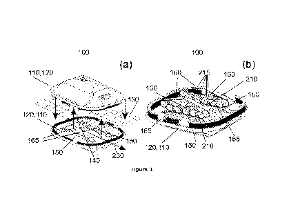
[0023] Figure la is a schematic representation of a cleaning device where the
first
cleaning unit and the second cleaning unit may be seen as positioned on
opposite
sides of a net,
[0024] Figure lb is a schematic representation of the cleaning device where
one cleaning
unit is illustrated as transparent to visualise belt assemblies of the two
cleaning
units adjoining each other,
[0025] Figure 2a is a schematic representation of a belt assembly comprising a
rear road
wheel, a middle road wheel, a front road wheel and a track,
[0026] Figure 2b is a schematic representation of a belt assembly comprising a
rear road
wheel, a middle road wheel, a front road wheel, a damper wheel and a track,
[0027] Figure 3 is a schematic representation of a belt assembly that
simultaneously
visualizes several embodiments of the invention,
[0028] Figure 4 is a schematic representation of a track comprising friction
studs, and
[0029] Figure 5 is a schematic representation of a belt assembly where each
road wheel
and at least one damper wheel are provided with suspension.
Detailed description of the invention
[0030] In the following, general embodiments as well as particular exemplary
embodiments of the invention will be described. References will be made to the
accompanying drawings. It shall be noted, however, that the drawings are
exemplary embodiments only, and that other features and embodiments may
well be within the scope of the invention as claimed.
[0031] Unless otherwise defined, all terms of art, notations and other
scientific terms or
terminology used herein are intended to have the meanings commonly
understood by those of skill in the art to which this invention pertains.
Certain
terms of art, notations, and other scientific terms or terminology may,
however,
find a definition in the field of continuous propulsion systems, or they may
be
defined specifically as indicated below.
[0032] The present invention provides a cleaning device 100 for cleaning a
submerged
net 130, e.g. that of a fish pen. The cleaning device 100 according to the
invention comprises a first cleaning unit 110 for being positioned on a first
side of
the net 130 and a second cleaning unit 120 for being positioned on a second
side
of the net 130, opposite to the first cleaning unit 110. The first cleaning
unit 110
CA 03227708 2024-2- 1
WO 2023/014229
PCT/N02022/050187
5/18
and second cleaning 120 unit are, as illustrated in figure la and lb, each
provided with two parallelly oriented belt assemblies 150. Each belt assembly
150 comprises a rear road wheel 170, a middle road wheel 180, a front road
wheel 190 and a track 160. The terms "front", "middle" and "rear" are here
defined relative to the driving direction 230 of the cleaning device 100.
However,
as the driving direction 230 may be reversed, said terms are largely used
herein
to refer to the relative position of the road wheels 170,180,190, meaning in
practice that the middle road wheel 180 is placed between the front road wheel
190 and the rear road wheel 170. A belt assembly 150 may in the context of the
present invention be understood by a person skilled in the art as the
collection of
wheels, track 160, bearings, supports, etc. for enabling continuous track
propulsion of the cleaning units 110,120, and hence the cleaning device 100.
[0033] Each belt assembly 150 of the cleaning units 110,120 may, as
illustrated in figure
la and lb, be arranged such that the ground pad 165 of the track 160 protrudes
a non-zero distance from the underside of a cleaning unit 110,120. The ground
pad 165 of each belt assembly 150 of the first cleaning unit may thus in other
words be said to protrude a nonzero distance from the underside of the first
cleaning unit 110, while the ground pad 165 of each belt assembly 150 of the
second cleaning unit 120 may be said to protrude a nonzero distance from the
underside of the second cleaning unit 120. A person skilled in the art will
appreciate that the ground pad 165 of any belt assembly 150 may be interpreted
as the part of a track 160 that lies between any two road wheels. A ground pad
165 may thus be considered as a part of a track 160. The ground pad 165 of any
track 160 may according to the invention be considered as planar, or at least
essentially planar, where "essentially planar" may be interpreted as meaning
for
example that the ground pad 165 of any belt assembly 150 occasionally may be
tilted by a few degrees, or become at least in part wavy, e.g. due to the
track
160 not being completely tight.
[0034] The first cleaning unit 110 and second cleaning unit 120 may, as
illustrated in
figure la, be arranged on opposite sides of the net 130 to be cleaned. The
first
cleaning unit 110 and second cleaning unit 120 may be aligned relative to one
another such that the two belt assemblies 150 of the first cleaning 110 unit
are
aligned with and adjoins separate belt assemblies 150 of the second cleaning
unit
120. The ground pad 165 of each respective track 160 of each belt assembly 150
of the first cleaning unit 110 may, as illustrated in figure lb, be positioned
such
that each ground pad 165 adjoins the ground pad 165 of the track 130 of
CA 03227708 2024-2- 1
WO 2023/014229
PCT/N02022/050187
6/18
separate belt assemblies 150 of the second cleaning unit 120. Note that in
figure
lb one of the cleaning units of the cleaning device is schematically
illustrated as
transparent for illustrative purposes. A person skilled in the art with
knowledge of
the present invention will appreciate that a net 130 to be cleaned may be
present
between any two ground pads 165 described as adjoining in the above context.
Figure la and lb illustrates an example where the first cleaning unit 110 and
second cleaning unit 120 are positioned on opposite sides of a net 130 to be
cleaned such that the ground pad 165 of the track 160 of each belt assembly
150
of the first cleaning 110 unit adjoins, via the net 130 to be cleaned, a
ground pad
165 of the track 160 of a belt assembly 150 of the second cleaning unit 120.
[0035] The track 160 of each belt assembly 150 is, as illustrated in figure
lb, provided
with magnets 210. The magnets 210 are provided in order to generate an
attractive force between the belt assemblies 150 of the first cleaning unit
110
and the belt assemblies 150 of the second cleaning unit 120 such that the
cleaning device 100 may adhere to a net 130 to be cleaned. A track 160 of a
belt
assembly 150 of the first cleaning unit 110 may as a way of example comprise
magnets 210 with a first polarity, while a track 160 of a belt assembly 150 of
the
second cleaning unit 120 may comprise magnets 210 with a second polarity,
opposite to the first polarity. When the tracks 160 of said two belt
assemblies
150 are positioned such that they adjoin, an attractive force will occur
between
them such that a frictional force will be obtained between each cleaning unit
110,120 and the net 130 to be cleaned. The cleaning device 100 will thus, due
to
this attractive force and resulting frictional force, adhere to the net 130 to
be
cleaned such that the two cleaning units 110,120 may maintain a position on
the
net 130 relative to one another. A person skilled in the art will appreciate
that
there are numerous degrees of freedom in the configuration of the magnets 210
in each track 160. The magnets 210 in two adjoining tracks 160 may as a way of
example be such that all the magnets 210 of a first track 160 have the same
polarity, while all the magnets 210 in a second track 160, adjoining the first
track
160, have the opposite polarity. Another example is that the magnets 210 in
two
adjoining tracks 160 may be such that any two adjacent magnets 210 in any one
track 160 have opposite polarity, but where the tracks 160 of the two cleaning
units are adjoining with a shift such that magnets 210 of opposite polarity
are
adjoining/attracting one another.
[0036] The cleaning device may according to the invention move across a net to
be
cleaned by means of the belt assemblies of the first and second cleaning unit.
CA 03227708 2024-2- 1
WO 2023/014229
PCT/N02022/050187
7/18
The adhesion to the net obtained by the magnetic attraction between adjoining
tracks of the two cleaning units will result in a grip for the cleaning device
such
that movement is enabled. Said grip may thus be termed a magnetic induced
grip. A person skilled in the art with knowledge of the present invention will
appreciate that each belt assembly of the cleaning device may operate as a
continuous track vehicle propulsion system that is configured to operate under
water, i.e. where each belt assembly is provided with one or more of an
engine,
gear system, watertight gaskets, power supply, etc. The cleaning units may
generally be provided with other parts necessary for allowing the cleaning
device
to move across a net to be cleaned. A person skilled in the art with knowledge
of
the present invention will appreciate that such parts may comprise e.g.
watertight housing, transmitter, receiver, lighting device, battery, etc.
[0037] The middle road wheel 180 of each belt assembly 150 may as
schematically
illustrated in figure 1, 3 and 5 be provided with wheel magnets 215. The wheel
magnets 215 may be provided in order to generate/cause an attractive force
between the middle road wheel 180 and the track 160 of each belt assembly 150
such that the track 160 is kept in contact with the middle road wheel 180
during
operation of the cleaning device. The latter may for example contribute to a
smoother moment of the cleaning device 100, reducing wobbling of the track
160, but also contribute to reducing the risk of the net being cleaned to be
stuck
between the middle road wheel 180 and the track 160. The attractive force may
occur between the magnets 210 of the track 160 and the wheel magnets 215 of
the middle road wheel 180. Alternatively, the track 160 may be provided with
separate magnets that interact with the wheel magnets 215 of the middle road
wheel 180 to generate said attractive force. A person skilled in the art with
knowledge of the present invention will appreciate that the configuration of
wheel
magnets 215 in the middle road wheel 180 may vary and that many
configurations are possible. One example is that all the magnets 210 in the
track
160 are arranged with one polarity and that all the wheel magnets 215 of the
middle road wheel 180 are arranged with the opposite polarity to generate an
attraction with the magnets 210 of the track 160. Another example is that the
magnets 210 in the track 160 are arranged with alternating polarity and that
all
the wheel magnets 215 of the middle road wheel 180 also are arranged with an
alternating polarity. The distance between two adjacent wheel magnets 215 in
the middle road wheel 180 may for example be the same as the distance
between two adjacent magnets 210 in the track 160, and the middle road wheel
CA 03227708 2024-2- 1
WO 2023/014229
PCT/N02022/050187
8/18
180 may further be synchronised with the track 160 such that each wheel
magnet 215 of the middle road wheel 180 always are aligned with a magnet 210
of the track 160.
[0038] The middle road wheel 180 of each belt assembly 150 may, as an
alternative to
being provided with wheel magnets 215, be provided with a magnetic
component. The magnetic component may thus interact with the magnets 210 in
the track 160 to cause an attractive force to occur between the middle road
wheel 180 and the track 160. The magnets 210 of the track 160 will in other
words attract the magnetic component and hence the middle road wheel 180.
The magnetic component may for example be a magnetic ring, such as an iron
ring. The middle road wheel 180 of each belt assembly 150 may further be
provided with a plurality of magnetic components, such as a plurality of iron
pellets or similar. The middle road wheel 180 of each belt assembly 150 may
alternatively in itself be magnetic, i.e., said magnetic component may be
interpreted as a metallic element at least in part constituting the middle
road
wheel 180.
[0039] The cleaning device may according to the invention be dimensioned
according to
the net to be cleaned. A typical extension of the cleaning device is between
80
cm and 200 cm. The extension of the cleaning device is according to a specific
embodiment of the invention less than 150 cm.
[0040] Each road wheel 170,180,190 is, as schematically illustrated in figure
5, provided
with a suspension 200. The suspension 200 for each road wheel 170,180,190
may be configured for shifting the position of said road wheel 170,180,190 in
a
direction at least in part perpendicular to a driving direction 230 of the
cleaning
device. An example of such a distance is less than 10 centimetres, or more
specifically a distance of between 3 and 5 centimetres. The suspension 200 of
the
road wheels 170,180,190 aims inter alia to enable the cleaning device to
traverse
obstacles of the net to be cleaned, such as ropes, knots or similar. The
combination of the road wheel suspension 200 and the presence of three road
wheels 170,180,190 means that any two adjoining tracks 160 may retain
magnetic attraction even when the cleaning device is traversing an obstacle.
As a
way of example one can assume a cleaning device according to the invention
traversing a rope of the net to be cleaned. As the cleaning device drives
across
the rope, the front road wheels 190 of each pair of adjoining tracks 160 will
be
displaced away from one another and the magnetic attraction between the part
of the ground pad 165 between the front road wheel 190 and middle road wheel
CA 03227708 2024-2- 1
WO 2023/014229
PCT/N02022/050187
9/18
180 of the pair of adjoining tracks 160 will be strongly reduced. A cleaning
device
having only two road wheels would in such an instance likely lose its magnet-
induced grip on the net to be cleaned and consequently fall of the net. The
cleaning device according to the present invention would on the contrary
maintain its magnet induced grip on the net, as the part of the ground pad 165
between the middle road wheel 180 and read road wheel 170 would still be
adjoining, such that sufficient magnetic attraction may be maintained.
Following
the same example, the cleaning device will upon continuing its traversing of
said
rope move relative to the rope such that the front road wheels 190 once again
are brought in contact with each other, but where the middle road wheels 180
subsequently are displaced from their default position using their respective
suspension 200. At such a position the cleaning device according to the
invention
may maintain its adhesion to the net to be cleaned due to the magnet
attraction
between the ground pad 165 around the front road wheels 190 and the rear road
wheels 170. The cleaning device will upon continuing its traversing of said
rope,
move relative to the rope such that the middle road wheels 180 once again are
brought in contact with each other, but where the rear road wheels 170
subsequently are displaced from their default position using their respective
suspension 200. The latter situation is equivalent to the situation where the
front
road wheels 190 were displaced.
[0041] Figure 2b, 3 and 5 illustrates an embodiment of the invention where
each belt
assembly 150 further comprises a damper wheel 220. Said damper wheel 220
may typically be positioned at a non-zero distance from the ground pad 165 of
the belt assembly 150 to which it belongs. The latter location may here be in
a
direction perpendicular to the driving direction 230 of said belt assembly
150. A
damper wheel 220 may be utilized to compensate for any strain in a track 160
caused when the cleaning device traverses an obstacle that causes one of its
road wheels 170,180,190 to be displaced from their non-damped position. A road
wheel 170,180,190 being displaced because the cleaning device traversing an
obstacle will result in the relevant track 160 having to conform to the shape
of
the traversed object. Instead of the track 160 becoming strained due to the
displacement of a road wheel 170,180,190, the damper wheel 220 may instead
compensate for the shift in position of the road wheel 170,180,190, i.e.
compensate for the resulting strain in the track 160, by being itself
displaced.
Each damper wheel 220 may thus in other words be provided with a suspension
200 for shifting the position of said damper wheel 220 to compensate for a
shift
CA 03227708 2024-2- 1
WO 2023/014229
PCT/N02022/050187
10/18
in position of a road wheel 170,180,190. As a way of example, if a road wheel
170,180,190 of a belt assembly 150 is displaced in a direction perpendicular
to
the driving direction 230 of said belt assembly 150, a damper wheel 220 of
that
belt assembly may be displaced in the opposite direction of the displaced road
wheel 170,180,190 in order to compensate for the increased length requirement
on the track 160 due to the belt having to conform to the shape of the object
that is being traversed. A typical object that needs to be traversed may as
previously mentioned be a rope or a knot, which for example could have a
diameter or extension of 3-5 centimetres. Each road wheel 170,180,190 may
thus be provided with a suspension 200 for shifting the position of said road
wheel 170,180,190 a distance of at least 3-5 centimetres in a direction at
least in
part perpendicular to a driving direction 230 of the cleaning device. Each
damper
wheel 220 may consequently be provided with a suspension 200 for shifting the
position of said damper wheel 220 a distance of 3-5 centimetres. In general,
any
road wheel 170,180,190 may be provided with a suspension 200 for shifting the
position of said road wheel 170,180,190 a distance up to 10 centimetres in a
direction at least in part perpendicular to a driving direction 230 of the
cleaning
device. A suspension 200 may generally be any suitable suspension 200.
Examples of suitable suspensions 200 are spring-based suspension and hydraulic
suspension.
[0042] According to an embodiment of the invention any one or more of the rear
road
wheel 170, the front road wheel 190 and/or the damper wheel 220 of each belt
assembly 150 may be provided with wheel magnets 215. The wheel magnets 215
may be provided to generate an attractive force between any one or more of the
rear road wheel 170, the front road wheel 190 and/or the damper wheel 220 and
the track 160 of each belt assembly 150. The configuration of the wheel
magnets
215 may be the same as described for the middle road wheel 180. Figure 1
schematically illustrates a cleaning device where any one or more of the rear
road wheel 170, the front road wheel 190 and/or the damper wheel 220 of each
belt assembly 150 is/are provided with wheel magnets 215. Any one or more of
the rear road wheel 170, the front road wheel 190 and/or the damper wheel 220
of each belt assembly 150 may, as an alternative to being provided with wheel
magnets 215, be provided with a magnetic component. The magnetic component
may here be provided as described for the middle road wheel 180.
[0043] The cleaning device 100 may, as illustrated in figure la and lb be
provided with
cleaning means 140 for cleaning a submerged net 130. Both or either of the
first
CA 03227708 2024-2- 1
WO 2023/014229
PCT/N02022/050187
11/18
cleaning unit 110 and second cleaning unit 120 may be provided with cleaning
means 140. Cleaning means 140 may according to the invention be any suitable
means for cleaning a net 130. As a way of example, the cleaning device 100 may
be provided with one or more brushes, e.g. a rotating brush. The one or more
brushes may be provided on only one of the cleaning units 110,120 or
alternatively be distributed between the two cleaning units 110,120. A brush
may
upon rotation move across the net to clean the net of unwanted substances such
a biofouling. In another example the cleaning means may comprise a water-
based cleaning device, such as a pressure cleaner. In yet another example the
cleaning means may comprise one or more friction surfaces, such as a scrub or
stationary brush, suitable for cleaning a net by being moved across the net
130.
[0044] The cleaning device may according to any embodiment of the invention be
configured to traverse obstacles of a given size. As a way of example, the
cleaning device may be configured to traverse an obstacle such as a rope or a
rope knot. In order for the cleaning device to not loose adhesion to the net
to be
cleaned upon traversing an obstacle, the road wheels of each belt assembly may
be spaced apart depending on the dimension of the obstacle to be traversed. In
one embodiment of the invention the road wheels of each individual belt
assembly may be separated by a distance of at least 3-5 centimetres. The
latter
distance is here measured between the surface of two adjacent road wheels. The
road wheels of each individual belt assembly may generally be separated by a
distance longer than 5 centimetres. It will be appreciated by a person skilled
in
the art that the upper limit for the spacing between two adjacent road wheels
of
the same belt assembly is determined by for example the obstacle that it is
desirable to traverse, and/or for example the dimension and weight of the
cleaning device. A distance between two adjacent road wheels of at least 3-5
centimetres, alternatively 5 ¨ 10 centimetres, is considered adequate for most
fish pen. Such a distance will allow the cleaning device to traverse ropes and
rope knots without having two adjacent road wheels of the same belt assembly
being displaced by the rope.
[0045] Any belt assembly may, as illustrated in figure 3 and 5, further
comprise any
number of drive wheels 320, damping wheels 220, road wheels, idlers 330
and/or tightener wheels 340. As a way of example, any belt assembly may be
provided by a driving wheel 320, i.e. a wheel that supplies driving power to
the
track 160. Any road wheel or damper wheel 220 may in any relevant
embodiments of the invention be a driving wheel 320. A person skilled in the
art
CA 03227708 2024-2- 1
WO 2023/014229
PCT/N02022/050187
12/18
would appreciate that the cleaning device according to the present invention
may
comprise any number of additional wheels, e.g. dependent on the exact size and
shape of the belt assemblies 150. A tightener wheel 340 may for example be
provided to form the previously described driving edge 230 or trailing edge
250.
In a particular embodiment of the invention, each belt assembly 150 may
further
comprise an additional middle road wheel 180. An additional middle road wheel
180 may contribute to increase the attraction between two adjoining belt
assemblies 150 when the cleaning device traverses an obstacle. An additional
middle road wheel 180 may contribute to ensuring a plane surface of the ground
pad 165 of two adjoining tracks 160 being in contact during the traversing of
said
obstacle.
[0046] According to an embodiment of the invention, any one or more of said
any
number of drive wheels 320, damping wheels 220, road wheels, idlers 330
and/or tightener wheels 340 may be provided with wheel magnets 215. Said
wheel magnets 215 may here be used to generate an attractive force between
any one or more of said any number of drive wheels 320, damping wheels 220,
road wheels, idlers 330 and/or tightener wheels 340 and the track 160 of each
belt assembly 150. The configuration of the wheel magnets 215 in this
embodiment may be the same as described for the middle road wheel 180.
Figure 5 schematically illustrates a belt assembly where any one or more of
said
drive wheels 320, damping wheels 220, road wheels, idlers 330 and/or tightener
wheels 340 is/are provided with wheel magnets 215. Any one or more of said any
number of drive wheels 320, damping wheels 220, road wheels, idlers 330
and/or tightener wheels 340 of each belt assembly 150 may, as an alternative
to
being provided with wheel magnets 215, be provided with a magnetic
component. The magnetic component may here be provided as described for the
middle road wheel 180.
[0047] It will be appreciated by a person skilled in the art with knowledge of
the present
invention that the cleaning device will function without any of the wheels of
the
cleaning device being provided with wheel magnets or a magnetic component.
Wheel magnets and a magnetic component may thus, in any embodiment of the
invention, be omitted.
[0048] Each belt assembly 150 may, as illustrated in figure 3, be arranged
such that the
track 160 of each belt assembly 150 forms a leading edge 240 and/or trailing
edge 250. Any leading edge 240 and/or trailing edge 250 may thus form a non-
zero angle with a driving direction 230 of said belt assembly 150. A non-zero
CA 03227708 2024-2- 1
WO 2023/014229
PCT/N02022/050187
13/18
leading edge 240 may lead to eased traversing of obstacles, as such a leading
edge 240 will reduce the angle with which the track 160 engages a given
obstacle to be traversed. Said angle may sometimes be defined as an
engagement angle or alternatively as an angle of attack. A further non-zero
trailing edge 250 is optional and will have the same technical effect as the
leading edge 240 in the event of the cleaning device reversing across an
obstacle. A trailing edge 250 may additionally or alternatively be utilized in
order
to ease disengagement between magnets 210 of two adjoining tracks 160 as the
cleaning device moves forward. A track 160 of a first cleaning unit adjoining
a
track 160 of a second cleaning unit will, due to the presence of magnets 210
in
each track 160, experience a magnetic attraction towards each other. As the
cleaning device moves forwards, magnets 210 of two adjoining tracks 160 will
continuously engage in the front of the ground pad 165 and disengage at the
trail
of the ground pad 165. The magnets 210 disengaging at the trail of the ground
pad 165 will have to be separated by a force greater than the attractive force
caused by the magnets 210. Two tracks 160 forming a trailing edge 250 will
cause a reduction of the required force for pulling apart magnets 210 of
adjoining
tracks 160, as the presence of a trailing edge 250 will allow for more of a
pealing
motion to be performed. Here the magnetic attraction between two engaged
magnets 210 may be overcome more gradually than what would have been the
case without a trailing edge 250. Any leading edge 240 and/or trailing edge
250
may, as illustrated in figure 3 be formed between a road wheel and an
additional
wheel, where the additional wheel is positioned a non-zero distance in a
direction
perpendicular to the driving direction. Said additional wheel may for example
be
a driving wheel 320.
[0049] The size of each wheel of the cleaning device will generally depend on
the size of
each cleaning unit. The size of each wheel may typically be dimensioned
according to the type of track used, for example such that the track may run
across the wheels without experiencing too great a curvature. In a particular
embodiment of the invention each wheel of each belt assembly has a diameter in
the range of 60 mm to 120 mm. Such a diameter has been found to be
preferable when the track is made from silicone, rubber or plastic. Any wheel
of a
belt assembly that is positioned farthest to the front or back along the
driving
direction of a belt assembly will typically inflict the largest curvature on
the track.
These farthermost wheels may thus have a diameter that is larger than that of
any road wheels appurtenant to the same belt assembly, e.g. in the range from
CA 03227708 2024-2- 1
WO 2023/014229
PCT/N02022/050187
14/18
10% - 250% larger, in particularly in the range from 50% - 100 A, larger. Any
one or both of the farthermost wheels may for example be a driving wheel 320.
[0050] The track 160 of each belt assembly 150 may as illustrated in figure 3
of the
invention be provided with a plurality of studs 270, while each wheel of each
belt
assembly 150 may be provided with corresponding recesses 280 for receiving the
studs 270 of the track 160. The studs 270 may provide an engagement between
the wheels of a belt assembly 150 and the track 160 of the same belt assembly
150 such that grip is provided between the wheels and the track 160. The studs
270 may for example be used in order for a drive wheel 320 to provide
propulsion to a track 160. The studs 270 may generally be evenly positioned
along the longitudinal direction of the track, but any configuration is in
principle
possible.
[0051] Figure 3 illustrates a cleaning device where each track 160 is provided
with studs
270 and where each stud 270 of each track 160 of the cleaning device comprises
a magnet 210. The number of studs 270 comprising a magnet 210 may
alternatively be lower than the total number of studs 270 per track. The
latter
configuration may for example be used to optimize the magnetic attraction
between the first cleaning unit and the second cleaning unit. In a particular
example, the track 160 of each belt assembly 150 may be provided with an even
number of studs 270, where the polarity of the magnets 210 of any two adjacent
studs 270 are opposite to each other. Two adjoining tracks 160 will thus
experience an attractive force to one another between pairs of magnets 210
comprising studs 270 with opposite polarity. The latter configuration may be
beneficial to avoid the tracks 160 skidding, as the alternating polarity of
the
magnets 210 will create a force between two adjoining tracks 160 at least in
part
parallel with the driving direction 230 of the cleaning device.
[0052] Figure 3 illustrates a particular embodiment of the invention where
each track
160 of the cleaning device is provided with studs 270. Here, each track 160
comprises a plurality of rigid track elements 290 connected together by
flexible
joints 300, where each track element 290 is provided by at least one stud 270.
Each stud 270 is in this example placed a non-zero distance from any of the
flexible joints 300 connecting the track-elements 290, which inter alia
prevents
the studs 270 from being bent when the track 160 is moving. The latter can
contribute to reducing wear on the belt assembly. A flexible joint 300 may
generally be considered as any suitable joint that is flexible, such as a
hinge or
an elastic material connecting two adjacent rigid track elements 290.
CA 03227708 2024-2- 1
WO 2023/014229
PCT/N02022/050187
15/18
[0053] The track of any belt assembly of the cleaning device may according to
any
embodiment of the invention be made at least in part from rubber, plastic or
silicone. A person skilled in the art will appreciate that the track may be
made
from other materials than those listed explicitly herein. The track may for
example be made from a combination of materials, e.g. a combination of those
mentioned above.
[0054] Figure 4 illustrates a track 160 of a belt assembly of the cleaning
device where
the track 160 is provided with friction studs 310. The friction studs 310 are
here
provided on the side of the track 160 that is configured to face away from any
road wheels. The friction studs 310 are provided in order to improve the grip
between two adjoining tracks, and also between the track 160 and the net to be
cleaned. The friction studs 310 may according to an embodiment of the
invention
protrude up to 1 mm from the track, or alternatively up to 2 mm. Such a
protrusion distance has been found to be preferred, as larger protrusion
distances may contribute to unwanted wear on the net to be cleaned.
[0055] It will be appreciated that the cleaning device according to any
embodiment of
the invention is not limited to cleaning a net. The cleaning device may
according
to any embodiment of the invention alternatively be used to clean a seine, net
cage, a water permeable sheet, water impermeable sheet or similar. Other
examples are watertight tarpaulin, perforated tarpaulin, or similar.
[0056] A cleaning device according to any embodiment of the first aspect of
the
invention may thus in a second aspect of the invention be used for cleaning a
net
or sheet of a fish pen.
[0057] Other advantageous features will be apparent from the accompanying
claims.
CA 03227708 2024-2- 1