Note: Descriptions are shown in the official language in which they were submitted.
CA 03229281 2024-02-13
WO 2023/023006 PCT/US2022/040393
- 1 -
MACROENCAPSULATION DEVICES
CROSS-REFERENCE TO RELATED APPLICATION
[0001] This application claims the benefit under 35 U.S.C. 119(e) to
U.S. Provisional
Application Serial No.: 63/233,667, filed August 16, 2021, which is herein
incorporated by
reference in its entirety.
FIELD
[0002] Disclosed embodiments are related to macroencapsulation devices
and their
methods of manufacture.
BACKGROUND
[0003] Therapeutic devices that deliver biological products can be used
to treat metabolic
disorders, such as diabetes. The therapeutic devices may be implantable to
provide a biological
product, such as insulin, for an extended period of time. Some of these
devices include
macroencapsulation devices used to house cells to produce the desired
biological product, a
matrix including the cells, or other desired therapeutics within.
SUMMARY
[0004] Various embodiments of macroencapsulation devices are described
herein. The
various embodiments of the disclosed macroencapsulation devices may provide
improvements
related to the manufacturability, fatigue resistance, compatibility with
automation, and/or other
benefits as described in further detail below.
[0005] In one embodiment, a macroencapsulation device for housing a
population of cells
comprises a first membrane and a second membrane disposed on the first
membrane. The first
membrane and the second membrane are bonded together to form a seal extending
around an
internal volume disposed between the first membrane and the second membrane.
The seal is
disposed radially inward from an outer perimeter of the first and second
membranes. The first
membrane and/or the second membrane is semipermeable. The macroencapsulation
device
further comprises a frame, wherein the first membrane and the second membrane
are disposed on
the frame, wherein the frame extends along at least a portion of the outer
perimeter of the first
and second membranes, and wherein the seal is disposed radially inwards from
the frame.
[0006] In another embodiment, a macroencapsulation device for housing a
population of
cells comprises a first membrane and a second membrane disposed on the first
membrane. The
CA 03229281 2024-02-13
WO 2023/023006 - 2 - PCT/US2022/040393
first membrane and the second membrane are bonded together to form a seal
extending around
an internal volume disposed between the first membrane and the second
membrane. The first
membrane and/or the second membrane is semipermeable. The macroencapsulation
device
further comprises a frame disposed on the first membrane or second membrane
that extends
along at least a portion of the perimeter of the first and second membranes,
wherein the frame
includes a fill port extending from an exterior portion of the frame to an
interior portion of the
frame, and wherein an opening of the fill port located on the interior portion
of the frame is in
fluid communication with the internal volume and is flush with an adjacent
portion of the
internal portion of the frame.
[0007] In another embodiment, a method of forming a macroencapsulation
device
comprises depositing a first membrane and a second membrane onto a frame,
wherein the first
membrane and the second membrane are bonded together to form a seal extending
around an
internal volume disposed between the first membrane and the second membrane,
and wherein the
seal is disposed radially inward from an outer perimeter of the first and
second membranes. The
method further comprises connecting the frame to the second membrane and/or
the first
membrane along the outer perimeter of the first and second membranes at one or
more locations
located radially outward from the seal.
[0008] In yet another embodiment, a method of forming a
macroencapsulation device
comprises disposing a first membrane and a second membrane on a first surface
of a frame,
wherein the frame includes a fill port extending from an exterior portion of
the frame to an
interior portion of the frame, and wherein the frame includes a second surface
located opposite
from the first surface. The method further comprises disposing a first flap of
the first membrane
on a portion of the first surface adjacent to the fill port, disposing a
second flap of the second
membrane on a portion of the second surface adjacent to the fill port such
that a portion of the fill
port is disposed between the first flap and the second flap, and sealing the
first flap and the
second flap with the frame such that the fill port is in fluid communication
with an interior
volume disposed between the first membrane and the second membrane.
[0009] It should be appreciated that the foregoing concepts, and
additional concepts
discussed below, may be arranged in any suitable combination, as the present
disclosure is not
limited in this respect. Further, other advantages and novel features of the
present disclosure will
become apparent from the following detailed description of various non-
limiting embodiments
when considered in conjunction with the accompanying figures.
[0010] In cases where the present specification and a document
incorporated by reference
include conflicting and/or inconsistent disclosure, the present specification
shall control. If two
CA 03229281 2024-02-13
WO 2023/023006 - 3 - PCT/US2022/040393
or more documents incorporated by reference include conflicting and/or
inconsistent disclosure
with respect to each other, then the document having the later effective date
shall control.
BRIEF DESCRIPTION OF DRAWINGS
[0011] The accompanying drawings are not intended to be drawn to scale.
In the
drawings, each identical or nearly identical component that is illustrated in
various figures may
be represented by a like numeral. For purposes of clarity, not every component
may be labeled
in every drawing. In the drawings:
[0012] Fig. lA is a front view of a bonded membrane of a
macroencapsulation device
prior to mounting to a frame, according to one embodiment;
[0013] Fig. 1B is a side view of the embodiment of Fig. 1A;
[0014] Fig. 2A is a front perspective view of a frame of a
macroencapsulation device,
according to one embodiment;
[0015] Fig. 2B is an enlarged view of section 2B of the embodiment of
Fig. 2A;
[0016] Fig. 2C is a front view of the frame of the embodiment of Fig. 2A;
[0017] Fig. 2D is a front enlarged view section 2D of Fig. 2C;
[0018] Fig. 2E is a side view of the frame of the embodiment of Fig. 2A;
[0019] Fig. 2F is an enlarged side view of section 2F of Fig. 2E;
[0020] Fig. 3A is a front view of a macroencapsulation device, according
to one
embodiment;
[0021] Fig. 3B is an enlarged perspective view of a section of the
embodiment of Fig.
3A;
[0022] Fig. 3C is a side view of the macroencapsulation device of the
embodiment of Fig.
3A;
[0023] Fig. 3D is a side view of the macroencapsulation device of the
embodiment of
Fig. 3A after loading with a desired material;
[0024] Fig. 4 shows a process for connecting a bonded membrane to a
frame, according
to one embodiment;
[0025] Fig. 5A is a front view of a macroencapsulation device exhibiting
fatigue failure
due to stress concentrations at a bonded membrane perimeter; and
[0026] Fig. 5B is a front view of a macroencapsulation device exhibiting
fatigue failure
due to stress concentrations at an elongated fill port.
CA 03229281 2024-02-13
WO 2023/023006 - 4 - PCT/US2022/040393
DETAILED DESCRIPTION
[0027] Driven by a rising need to deliver biological products to treat
metabolic disorders,
such as diabetes, different types of implantable therapeutic devices have been
engineered.
However, the Inventors have recognized that typical methods of making such
devices are often
cumbersome and hard to control. For instance, there is often a lack of
precision and control in
forming specific structural features (e.g., mounting adhesive application)
associated with the
device. In addition, the Inventors have recognized that it is oftentimes
difficult to precisely form
these devices within accepted tolerances to prevent mechanical failure of
these devices once
implanted.
[0028] For example, in some embodiments, during a manufacturing process
of a
macroencapsulation device, at least one, and in some instances two or more
flexible membranes
of the device may be bonded together to form a seal perimeter extending around
an internal
volume disposed between the membranes. The flexible bonded membrane may be
mounted to a
corresponding semi-rigid frame and the two may be bonded together. The
Inventors have
recognized that the transition from the semi-rigid frame to the flexible
membrane may lead to
high stress concentrations at the membrane frame interface. Additionally,
imperfections in the
adhesive application at this interface may increase the localized stress on
the membrane during
repeated flexing of the device when implanted. These stress concentrations may
result in
delamination and/or membrane rupture due to fatigue failure. Other structural
features of the
frame, such as a fill port that extends into the internal volume disposed
between the membranes,
may also increase the local stresses applied to the membranes which may again
lead to accelerate
fatigue failure and membrane rupture during use.
[0029] In view of the above, the Inventors have recognized the benefits
associated with
macroencapsulation devices where the relative arrangement of the membranes and
frame of the
device, as well as adhesive application techniques to bond them together, may
be controlled to
modify one or more parameters of the resulting macroencapsulation devices. For
example, a
relative sizing and placement of the membranes and the associated frame may
provide a simple
and easily controllable method for producing macroencapsulation devices with
low stress and
risk of failure of the membranes at the frame interface. This may include
providing stress relief
between a frame and the seal perimeter of the bonded membranes held in the
frame to permit the
flexible unbonded membrane to accommodate relative deformation between the
more rigid frame
and seal perimeter. For example, the seal perimeter may be arranged radially
inward from an
outer perimeter of the membrane such that when the membrane is mounted to a
corresponding
perimeter frame, the seal perimeter is spaced radially inwards from the frame
with a unbonded
portion of the one or more membranes disposed between the frame and seal
perimeter. The space
CA 03229281 2024-02-13
WO 2023/023006 - 5 - PCT/US2022/040393
between the frame and the seal perimeter may create a stress buffer, which may
also be referred
to as a buffer region herein, between the frame and the membrane seal
perimeter which may
reduce fatigue failure of the membrane.
[0030] The Inventors have further recognized that it may be desirable to
prevent spread
of an adhesive used to bond one or more membranes of a device to an associated
frame into
undesirable adjacent locations of the membrane. This may include limiting the
spread of
adhesive into a buffer region between a frame and a seal perimeter extending
at least partially
around an internal volume of a device. The technique may include initial
bonding locations
arranged around the perimeter of the frame. The bonding sites may include
reservoirs in the
frame perimeter into which liquid adhesive is deposited and allowed to wick
therefrom into the
surrounding portions of the membranes. The viscosity, adhesive amount,
reservoir size, and
membrane properties may be selected to permit the adhesive to cure and bond
the membrane to
the frame while limiting the spread of the adhesive to the desired locations.
After the membrane
is bonded to the frame at each bonding site, a second adhesive application may
be used to deposit
either the same, or a different adhesive, around the frame perimeter in
sections between and/or
around the bonding sites to create a strong bond between the membranes and the
frame. In some
embodiments, both adhesive applications may leave an unbonded portion of the
membranes
disposed between the frame and a seal perimeter of the membranes to provide
the above noted
stress buffer.
[0031] Depending on the particular embodiment, the reservoir formed in a
frame for
receiving an adhesive during manufacture may have any appropriate size and/or
shape. For
example, in some embodiments, a size of the reservoirs included in a frame may
be between
about 50 i.t1_, and about 500 ilL. In some embodiments, a size of the
reservoirs included in a
frame has an average volume of about 250 ilL. In some embodiments, a size of
the reservoir
included in a frame is scaled by volume depending on design. For example, in
some
embodiments, a size of the reservoir included in a frame is about 1.6 lL/cm.
Additionally,
depending on the specific embodiment, the reservoirs may cover a surface area
of a mounting
surface on which the membranes are disposed by any desired amount including,
for example,
greater than or equal to 10%, 25%, and/or 50% of the surface area of the
portion of the frame the
membranes are mounted to it. Correspondingly, the reservoirs may cover less
than or equal to
80%, 75%, 50%, and/or 25% of the surface area of the portion of the frame the
membranes are
mounted to. Combinations of the foregoing ranges are contemplated including,
for example, the
reservoirs may cover between or equal to 10% and 80% of the surface area of a
portion of the
frame the membranes are mounted to. Individual reservoir volumes and areal
coverage both
CA 03229281 2024-02-13
WO 2023/023006 - 6 - PCT/US2022/040393
greater than and less than those noted above are also contemplated as the
disclosure is not so
limited.
[0032] In addition to the above, the Inventors have recognized that it
may be desirable to
avoid applying stresses to the membranes of a device due to the inclusion of
structures extending
into an interior volume of the device disposed between opposing portions of
the one or more
membranes. Thus, in some embodiments, an opening of a fill port in fluid
communication with
the interior volume may be flush with an adjacent inner portion of the frame
(i.e., the fill port
does not extend into the interior volume formed by the one or more membranes).
This may
reduce or eliminate stress concentrations and potential stresses applied to
the membranes due to
the use of a fill port extending into the membrane. The Inventors have
recognized and
appreciated techniques for sealing the bonded membrane around the flush
opening which are
expanded on further below. A population of cells has been shown to flow into a
sealed interior
volume of a bonded membrane with a flush-mounted opening just as well as with
a fill port that
extends into the membrane. For example, during testing of devices with flush
fill ports and fill
port extensions, the measured filling efficiency of devices with a flush fill
port were 93.33%
filled whereas devices with fill port extensions were 90% filled. In
embodiments including the
flush fill ports, the measured filling efficiency may be equal to or greater
than approximately
85%, 90%, 91%, 92%, 93, 94%, and/or 95%. The filling efficiency may also be
less than or
equal to approximately 99.99%, 99%, 98%, 97%, 96%, and/or 95%. In embodiments
including
the fill port extensions the measured filling efficiency may be between or
equal to approximately
80% and 99.99%, or more preferably between or equal to 90% and 99.99%.
However, other
combinations of the above ranges may also be used.
[0033] As noted above, a macroencapsulation device may include multiple
layers of
membranes. At least one exterior membrane of these multiple layers of
membranes may be
semipermeable. However, embodiments in which each of the membranes is
semipermeable or
where at least one of the membranes within a device are substantially
impermeable are also
contemplated. Further, a device may include two stacked membranes, three
stacked membranes,
and/or any other appropriate number of membranes as the disclosure is not
limited in this
fashion. For example, in one embodiment including two membranes, either
membrane may be
semipermeable and the other impermeable or both may be semipermeable.
Accordingly, it should
be understood that the current disclosure is not limited to any particular
combination of
membranes within a stacked structure.
[0034] In some embodiments, a macroencapsulation device may include at
least one
population of cells disposed within an internal volume of the device. For
example, the
population of cells may be disposed within an internal volume formed between
two or more
CA 03229281 2024-02-13
WO 2023/023006 - 7 - PCT/US2022/040393
opposing exterior membranes of the device where an exterior edge of the
internal volume may be
defined by one or more bonds extended around at least a portion, and in some
instances an entire,
perimeter of the membranes or other appropriate portion of the membranes. In
such an
embodiment, at least the exterior membranes of the device may be configured to
block passage
of the one or more populations of cells out of the device. Accordingly, the
one or more
populations of cells may be retained within the interior volume of the device.
While the use of
two exterior membranes forming a single internal volume is noted, the use of
multiple
intermediate membranes positioned between the exterior membranes of a device
and/or multiple
unconnected interior volumes within a device are also contemplated.
Additionally, instances in
which a single membrane is folded over and bonded to itself to provide two
opposing membranes
to form the interior volume are also contemplated.
[0035] In addition to retaining a population of cells within an interior
of a device, in some
embodiments, the membranes of a device may be configured to protect the one or
more
populations of cells disposed in an interior of the device from an immune
attack while permitting
the passage of a desired biological product, such as insulin, produced by the
cells as well as
waste and nutrients used and produced by the cells. In some embodiments, the
membranes are
configured to protect the cells from an immune attack in the absence of an
immune suppression
therapy. Depending on the particular embodiment, the desired exchange
properties and immune
response protection properties of the membrane may be based on: size exclusion
where a pore
size distribution of the membrane is selected to exclude immune cells based on
size; balancing
the diffusion kinetics of the larger immune cells through the membranes such
that it is
significantly less than the diffusion of the desired biological product, cell
waste, and nutrients
through the use of pore size, tortuosity, membrane thickness, and other
appropriate parameters;
combinations of the foregoing; and/or other appropriate exclusion techniques.
[0036] The membranes of a macroencapsulation device may be formed from any
appropriate biocompatible material. The biocompatible material may be
substantially inert
towards cells housed within the macroencapsulation device and the surrounding
tissue. The
biocompatible material may comprise a synthetic polymer or a naturally
occurring polymer. In
some embodiments, the polymer may also be a linear polymer, a cross linked
polymer, a network
polymer, an addition polymer, a condensation polymer, an elastomer, a fibrous
polymer, a
thermoplastic polymer, a non-degradable polymer, combinations of the
foregoing, and/or any
other appropriate type of polymer as the disclosure is not limited in this
fashion. In one
embodiment, a polymer may comprise expanded polytetrafluoroethylene (ePTFE).
Appropriate
types of polymers may also comprise polyvinylchloride (PVC), polyethylene
(PE),
polypropylene (PP), polymethylmethacrylate (PMMA), polystyrene (PS),
CA 03229281 2024-02-13
WO 2023/023006 - 8 - PCT/US2022/040393
polytetrafluoroethylene (PTFE), expanded polytetrafluoroethylene (ePTFE),
polyurethane (PU),
polyamide (nylon), polyethyleneterephthalate (PET), polyethersulfone (PES),
polyetherimide
(PEI), polyvinylidene difluoride (PVDF), polycaprolactone (PCL), poly(lactic-
co-glycolic acid)
(PLGA), poly-L-lactide (PLLA), polyacrylonitrile (PAN), electrospun PAN/PVC,
any
combination of the foregoing, and/or any other appropriate polymeric material.
In some
embodiments, a membrane used with any of the embodiments disclosed herein may
comprise
PVDF. In some embodiments, a membrane used with any of the embodiments
disclosed herein
may comprise electrospun PAN PVC. In some embodiments, a membrane used with
any of the
embodiments disclosed herein may comprise PES. In some embodiments, a membrane
used with
any of the embodiments disclosed herein may comprise PS. In some embodiments,
a membrane
used with any of the embodiments disclosed herein may comprise PAN. In some
embodiments, a
membrane used with any of the embodiments disclosed herein may comprise
polycarbonate. In
some embodiments, a membrane used with any of the embodiments disclosed herein
may
comprise polypropylene. The synthesis methods used for forming one or more of
the porous
membranes from the above noted polymeric materials may include, but are not
limited to,
expansion, solvent-casting, immersion precipitation and phase separation,
electrospinning,
methods that yield isoreticular network, methods that yield trabecular
network, or any other
appropriate method of forming a porous polymer membrane.
[0037] Sintering of a membrane may be used to alter the porosity and flux
properties of a
membrane. For example, the sintering may increase the porosity of the membrane
while
maintaining its pore structure. The sintering may also improve the mechanical
stability and
diffusive flux of the membrane. Thus, sintering may be used to alter the
porosity and/or
mechanical properties of the membranes, which in turn can be used to tune the
porosity and the
flux properties of the macroencapsulation device. Accordingly, in some
embodiments, any
desired combination of sintered and/or unsintered membranes may be used. For
instance, two
exterior membranes of a device may be bonded together where either a sintered
and unsintered
membrane are bonded together, two sintered membranes are bonded together, or
two unsintered
membranes are bonded together. Further, any number of intermediate membranes
positioned
between these exterior membranes may be used where these intermediate
membranes may be
sintered or unsintered.
[0038] The membranes of a macroencapsulation device as described herein may
be made
from porous membrane materials that are configured to allow for transport
through the
membranes of materials, such as a biological product, with a molecular weight
less than about
3000 kDa, 2000 kDa, 1000 kDa, 500 kDa, 400 kDa, 300 kDa, 200 kDa, 100 kDa, 50
kDa, 40
kDa, 30 kDa, 20 kDa, 10 kDa, 6 kDa, 5 kDa, 4 kDa, 3 kDa, 2 kDa, 1 kDa, and/or
any other
CA 03229281 2024-02-13
WO 2023/023006 - 9 - PCT/US2022/040393
appropriate range of molecular weights depending on the desired application.
For example, the
one or more membranes of a macroencapsulation device may be configured to
permit the flow of
insulin through the membranes which has a molecular weight of about 5.8 kDa.
[0039] To provide the desired selectivity, the porous membranes used with
the
macroencapsulation devices disclosed herein may have an open porous structure
with average
pore sizes that are greater than or equal to about 1 nm, 5 nm, 10 nm, 15 nm,
20 nm, 30 nm, 40
nm, 50 nm, 60nm, 70 nm, 80 nm, 90 nm, 100 nm, 200 nm, 300 nm, and/or any other
appropriate
size range. Correspondingly, the average pore size of the various membranes
described herein
may have an average pore size that is less than or equal to 2500 nm, 2000 nm,
1700 nm, 1500
nm, 1400 nm, 1300 nm, 1200 nm, 1100 nm, 1000 nm, 900 nm, 800 nm, 700 nm, 600
nm, 500
nm, 400 nm, 300 nm, 200 nm, 100 nm, 90 nm, 80 nm, 70 nm, 60 nm, 50 nm, 40 nm,
30 nm, 20
nm, and/or any other appropriate size range. Combinations of the foregoing are
contemplated
including, for example, an average pore size that is between or equal to 1 nm
and 20 nm, 1 nm
and 2500 nm, and/or any other appropriate combination. While specific average
pore sizes are
described above, it should be understood that any appropriate average pore
size may be used for
the various membranes described herein including average pore sizes both
greater than and less
than those noted above.
[0040] In some embodiments, charge exclusion properties may be included in
the
membrane. For example, a surface charge of the membranes may be modulated with
external
coatings, plasma treatments, or other surface treatments to achieve neutral,
positive, negative, or
zwitterionic properties based on the isoelectric point of the desired
ancillary agent. The agent
may be a protein, complexed small molecule, and/or any other appropriate agent
depending on
the desired application.
[0041] To provide sufficient strength and/or rigidity for a
macroencapsulation device, the
various membranes and frames may be made from materials that are sufficiently
stiff. The
desired stiffness may be provided via an appropriate combination of a
material's Young's
modulus (also referred to as an Elastic modulus), thickness, and overall
construction which may
be balanced with a desired permeability of the device. Appropriate Young's
moduli for the
various membranes and frames described herein may be at least 105 Pa, 106 Pa,
107 Pa, 108 Pa,
109 Pa, and/or 1010 Pa. Other appropriate Young's moduli for the various
membranes and frames
described herein may be used including moduli both greater than and less than
these ranges.
Ranges between the foregoing Young's moduli are contemplated including, for
example, a
Young's modulus between or equal to about 106 Pa and 1010 Pa. In some
embodiments, an
appropriate material for the frame may include polyetheretherketone (PEEK).
Appropriate
materials for the frame may also include, but are not limited to
polycarbonate, polyurethane,
CA 03229281 2024-02-13
WO 2023/023006 - 10 -
PCT/US2022/040393
polyetheretherketone (PEEK), Polyvinyl Chloride (PVC), poly(oxymethylene),
poly(methyl
methacrylate) (PMMA), thermoplastic polymer based composites, polypropylene,
fluorinated
ethylene propylene (FEP), low density polyethylene (LDPE), high density
polyethylene (HDPE),
ultra-high density polyethylene (UHDPE), polycaprolactone, poly(lactide),
poly(glycolic acid),
poly lactide-co-glycolide, ethylene vinyl acetate copolymer, polyamides,
poly(butylene)
therephthalate, and combinations of the forgoing. In some embodiments, an
appropriate material
for the frame includes polyetheretherketone (PEEK). In some embodiments, an
appropriate
material for the frame includes polypropylene. In some embodiments, an
appropriate material for
the frame includes fluorinated ethylene propylene (FEP). In some embodiments,
an appropriate
material for the frame includes ultra-high density polyethylene (UHDPE). In
other embodiments,
an appropriate material for the frame or portion of the frame may include
titanium, graphene,
stainless steel, or other appropriate biocompatible material exhibiting
sufficient rigidity to
function as a frame for the macroencapsulation device.
[0042] In
some embodiments, it may be desirable for one or more of the membranes
included within a macroencapsulation device to be hydrophilic to facilitate
loading of cells into
the macroencapsulation device and/or to facilitate the flow of one or more
fluids, biological
compounds, therapeutics, cell nutrients, cell waste, and/or other materials
through the
membranes of a device. Additionally, a hydrophilic outer membrane may also
reduce the
occurrence of fibrosis when the device is positioned in vivo. Accordingly, the
membranes of a
macroencapsulation device may either be made from a hydrophilic material
and/or treated with a
hydrophilic coating. Appropriate hydrophilic coatings may include, but are not
limited to
polyhydroxyacrylate, PEG, pHPA, carboxymethylcellulose, alginate, agarose,
and/or solute-
impregnated thermoplastic coatings. Appropriate hydrophilic materials may also
include, but are
not limited to an appropriate hydrophilic polymer, polyethylene glycol,
polyvinyl alcohol,
polydopanine, any combination thereof, and/or any other appropriate
hydrophilic material
capable of forming a coating on the membranes or that the membranes may be
made from.
[0043] The
membranes described in the various embodiments of macroencapsulation
devices described herein may be bonded to one another using any appropriate
bonding method as
the disclosure is not limited in this fashion. For example, adjacent membranes
may be bonded to
one another using an adhesive, an epoxy, a weld or other fusion based
technique (e.g. ultrasonic
bonding, laser bonding, physical bonding, thermal bonding, etc.), mechanical
clamping using a
frame or fixture, and/or any other appropriate bonding method. In one specific
embodiment,
adjacent membranes may be bonded using a heated tool that is used to press or
strike two or
more membranes against each other for a set fusion time with a predetermined
pressure and/or
CA 03229281 2024-02-13
WO 2023/023006 - 11 - PCT/US2022/040393
force. In view of the above, it should be understood that the current
disclosure is not limited to
the use of any particular method for bonding the membranes together.
[0044] In some embodiments, one or more thermal treatments may be applied
to a stack
of bonded membranes after the membranes have been bonded to each other, and in
some
instances after a frame has been attached to the membranes. For example, the
membranes may
be bonded together with a bond extending along a perimeter of the membranes
and/or one or
more bonds may be formed within an interior area of the membranes (e.g. within
the bonded
perimeter) prior to heat treatment of the membranes. This post bonding heat
treatment may
provide enhanced bonding of the membranes at the bonded regions. The specific
heat treatment
temperatures and durations to improve the bonding between the membranes may
vary depending
on the specific materials used. However, in some embodiments the heat
treatment temperature
may be between a glass transition temperature and a melting temperature of a
polymer
membrane.
[0045] In certain embodiments, it may be desirable to limit a maximum
thickness of a
macroencapsulation device in a direction perpendicular to a plane in which a
maximum
transverse dimension of the device lies. Accordingly, one or more interior
portions of first and
second membranes disposed within a frame may be bonded together to limit the
extent to which
the membranes may be displaced relative to one another. These bonded portions
of the
membranes may be dispersed uniformly within the interior portion of the
membranes located
within the frame. These bonded portions may have any appropriate shape
including, for example,
dots, lines, curves, or any other appropriate shape. While the bonded interior
portions may have
any appropriate size for a desired application, in one embodiment using bonded
dots, the
diameter of the bonded dots may be greater than or equal to about 0.5 mm, 0.75
mm, 1 mm, 1.25
mm, 1.5mm, and/or any other appropriate diameter. Correspondingly, the
diameter of the dots
may be less than or equal to about 3 mm, 2.75 mm, 2.5 mm, 2.25 mm, 2.0 mm,
and/or any other
appropriate diameter. Combinations of the above noted ranges are contemplated
including, for
example, a diameter that is between or equal to 0.5 mm and 3 mm. While
specific shapes and
size ranges are provided above, it should be understood that other shapes and
sizes both smaller
and greater than those noted above are contemplated as the disclosure is not
limited in this
fashion.
[0046] In some embodiments, it may be desirable to improve the
vascularization of a
macroencapsulation device. Accordingly, in certain embodiments, one or more
through holes
may be formed in the one or more bonded portions located within an interior
portion of the
membranes disposed radially inwards from a frame of the device. These through
holes may
permit vasculature to growth through the through holes in addition to growing
around the upper
CA 03229281 2024-02-13
WO 2023/023006 - 12 - PCT/US2022/040393
and lower surfaces of the device. The one or more through holes may be formed
in the bonded
portions of the membranes using laser ablation, mechanical puncture, cutting,
or any other
appropriate method of forming a through hole in the one or more bonded
portions of the
membranes. As described in further detail herein, in some embodiments, the one
or more
through holes may also be disposed radially inward relative to both an
unbonded stress buffer
region and a seal perimeter extending around a perimeter of a sealed internal
volume of the
device. This may help to avoid the formation of stress concentrations within
the membranes
adjacent to the frame.
[0047] Depending on the particular size of the bonded portions of a
membrane, different
size through holes may be used. For example, in some embodiments, a through
hole formed in a
bonded portion of a membrane may have a maximum transverse dimension, such as
a diameter,
that is greater than or equal to 0.25 mm, 0.5 mm, 0.75 mm, 1.0 mm, 1.25 mm,
1.5 mm, and/or
any other appropriate maximum transverse dimension. Correspondingly, the
maximum
transverse dimension of the through hole may be less than or equal to 2.0 mm,
1.5 mm, 1.25 mm,
1.0 mm, 0.75 mm, 0.5 mm, and/or any other appropriate maximum transverse
dimension.
Combinations of the above-noted ranges are contemplated including, for
example, a maximum
transverse dimension of the through holes formed in corresponding bonded
portions of a
membrane may be between or equal to 0.25 mm and 2.0 mm where the maximum
transverse
dimension of the through holes is also less than a corresponding maximum
transverse dimension
of the bonded portions of the membrane they are formed in. While particular
dimensions are
noted above, it should be understood that other ranges both greater than and
less than those noted
above are also contemplated as the disclosure is not so limited.
[0048] In some embodiments, the above noted bonded portions within an
interior area of
the device, and the corresponding through holes, may be formed prior to
mounting a frame on the
device while the membranes are located in a flat planar configuration. This
may simplify the
manufacturing process when dealing with flexible membranes mounted to a frame
with a desired
amount of slack which may complicate forming other features after being
mounted to the frame.
[0049] As elaborated on below, in some embodiments, one or more portions of
adjacent
membranes may be bonded together such that the interior volume within the
device is subdivided
into a plurality of interconnected channels, which in some embodiments may be
shaped like a
lumen though any appropriate shape or configuration of the channels may also
be used. The
channels may have an inner maximum transverse dimension, such as an inner
diameter, that is
greater than or equal to 40 iim, 50 iim, 100 iim, 200 iim, 300 iim, and/or 400
iim.
Correspondingly, the channels may have an inner maximum transverse dimension
that is less
than or equal to 800 iim, 700 iim, 600 iim, 500 iim, and/or 400 m.
Combinations of the foregoing
CA 03229281 2024-02-13
WO 2023/023006 - 13 - PCT/US2022/040393
are contemplated including, for example, an inner maximum transverse dimension
of the
plurality of channels that is between or equal to 40 iim and 800 iim. Further,
a density of the
interconnected channels forming the various compartments of a device may have
a density per
unity area within a transverse plane of the device that is greater than or
equal to about 10
channels/cm2, 15 channels/cm2, 20 channels/cm2, 25 channels/cm2, 30
channels/cm2, 35
channels/cm2, 40 channels/cm2, 45 channels/cm2, 50 channels/cm2, 60
channels/cm2, 70
channels/cm2, 80 channels/cm2, 90 channels/cm2, 100 channels/cm2, 110
channels/cm2, 120
channels/cm2, 130 channels/cm2, 140 channels/cm2, 150 channels/cm2, 175
channels/cm2, or 200
channels/cm2. Ranges extending between any of the above noted density of
channels are also
contemplated including, for example, a density of channels that is between or
equal to about 10
channels/cm2 and 200 channels/cm2. Though densities both greater than and less
than the ranges
described above are also contemplated.
[0050] A macroencapsulation device as described herein may have any
appropriate
combination of internal volumes, external dimensions, and/or other appropriate
physical
parameters. For example, an internal volume encompassed by the outer membranes
of a
macroencapsulation device may be between or equal to 40 i.tI, and 250 ilL. A
width, or
maximum transverse dimension, of the macroencapsulation device may also be
between about 20
mm and 80 mm. Additionally, to provide a desired diffusion of oxygen into the
interior of a
macroencapsulation device to support cells contained therein, a maximum oxygen
diffusion
distance from an exterior of the device to an interior portion of the device
including a population
of cells may be less than 50 iim, 100 iim, 150 iim, 200 iim, 250 iim, 300 inn,
350 iim, 400 iim,
450 iim, or 500 iim. In some embodiments, the maximum oxygen diffusion
distance from an
exterior of the device to an interior portion of the device including a
population of cells is less
than or equal to 150 um. In some embodiments, the maximum oxygen diffusion
distance from
an exterior of the device to an interior portion of the device including a
population of cells is less
than or equal to 200 um. In some embodiments, the maximum oxygen diffusion
distance from an
exterior of the device to an interior portion of the device including a
population of cells is less
than or equal to 250 um. Correspondingly, a maximum thickness, or dimension
perpendicular to
a maximum transverse dimension, of the overall device and/or an internal
volume located within
the device may be less than 50 iim, 100 iim, 150 iim, 200 iim, 250 iim, 300
iim, 350 iim, 400
iim, 450 iim, or 500 iim. In some embodiments, the maximum thickness, or
dimension
perpendicular to a maximum transverse dimension, of the overall device and/or
an internal
volume located within the device is less than or equal to 500 um. Further, in
some embodiments,
an outer surface area to volume ratio of the device may be greater than or
equal to about 20 cm-1,
40 cm-1, 60 cm-1, 80 cm-1, 100 cm-1, 120 cm-1, or 150 cm-1. Ranges extending
between any of the
CA 03229281 2024-02-13
WO 2023/023006 - 14 - PCT/US2022/040393
forgoing values for the various dimensions and parameters as well as ranges
both greater than
and less those noted above are also contemplated.
[0051] While specific dimensions, parameters, and relationships related to
the
macroencapsulation device and the materials it is made from are described
above, it should be
understood that dimensions, parameters, and relationships both greater than
and less than those
noted above are contemplated as the disclosure is not limited in this fashion.
Accordingly, any
appropriate combination of size, construction, material properties, and/or
relative performance
parameters may be used for a device depending on the desired application.
[0052] In some embodiments, a cell population contained within an interior
volume of a
macroencapsulation device is an insulin secreting cell population. In some
embodiments, the cell
population comprises at least one cell derived from a stem cell derived cell.
In some
embodiments, at least one cell is a genetically modified cell. In some cases,
at least one cell is
genetically engineered to reduce an immune response in a subject upon
implantation of the
device, as compared to comparable cells that are not genetically engineered.
In some
embodiments, the cell population is a stem cell derived cell that is capable
of glucose-stimulated
insulin secretion (GSIS). For example, an appropriate population of cells may
comprise
pancreatic progenitor cells, endocrine cells, beta cells, a matrix including
one or more of the
foregoing, or any combination thereof. Further, a matrix may comprise isolated
islet cells,
isolated cells from pancreas, isolated cells from a tissue, stem cells, stem
cell-derived cells,
induced pluripotent cells, differentiated cells, transformed cells, or
expression systems, which
can synthesize one or more biological products. Optionally, in some
embodiments, the matrix
may comprise a second type of cells that support the first type of cells that
synthesize one or
more biological products. In some embodiments, the cells may be encapsulated
before being
placed within the matrix. In such an embodiment, the cells may be encapsulated
in a
microcapsule or may be conformally coated. However, naked, i.e., uncoated,
cells may also be
used.
[0053] Depending on the particular embodiment, a therapeutically effective
density of
cells may be loaded into the interior volume of a macroencapsulation device.
Appropriate cell
densities disposed within an interior volume may be greater than or equal to
about 1000 cells/i.iL,
10,000 cells/i.iL, 50,000 cells/i.iL, 100,000 cells/i.iL, and/or 500,000
cells/i.iL. Appropriate cell
densities disposed within the compartment may also be less than or equal to
about 1,000,000
cells/i.iL, 500,000 cells/i.iL, 100,000 cells/i.iL, 50,000 cells/i.iL, and/or
10,000 cells/i.iL.
Combinations of the foregoing are contemplated including cell densities
between about 1000
cells/i.iL and 1,000,000 cells/i.iL. In some embodiments, the cell density is
between about
CA 03229281 2024-02-13
WO 2023/023006 - 15 - PCT/US2022/040393
100,000 cells/uL and 1,000,000 cells/uL. Cell densities both greater than and
less than those
noted above may also be used depending on the desired application and cell
types being used.
[0054] Depending on the specific application and desired duration of use, a
macroencapsulation device may be configured to have any appropriate fatigue
life when
implanted in vivo within a subject. For example, in some embodiments, a
macroencapsulation
device may be configured for implantation within the abdominal tissue of a
subject where it may
be subjected to abdominal contractions during use. Accordingly, in some
embodiments, a fatigue
life of a macroencapsulation device may be greater than or equal to 50,000
cycles, 60,000 cycles,
70,000 cycles, 80,000 cycles, 90,000 cycles, 100,000 cycles, 150,000 cycles,
200,000 cycles,
300,000 cycles, 400,000 cycles, and/or 500,000 cycles. The fatigue life may
also be less than or
equal to 200,000 cycles, 100,000 cycles, and/or 80,000 cycles. Combinations of
the foregoing
ranges are contemplated including, for example, a fatigue life that is between
or equal to 50,000
cycles and 200,000 cycles. In some embodiments, the fatigue life is between
1,000 and 50,000
cycles. In some embodiments, the fatigue life is between 50,000 and 100,000
cycles. In some
embodiments, the fatigue life is between 100,000 and 500,000 cycles. Devices
with a fatigue life
both greater than and less than those noted above are also contemplated as the
disclosure is not
limited in this fashion. For the purposes of this application, a fatigue life
of a macroencapsulation
device may be determined using the fatigue cycle testing procedures discussed
in the example
section using a cyclic load of between 12 N and 45 N which is similar to the
forces that may be
experienced by a device when implanted in vivo within the abdominal tissue of
a subject.
[0055] The macroencapsulation devices described herein may be implanted in
a subject in
vivo at various sites. In one example, a device may be implanted in a subject
by properitoneal or
retrorectus implantation. In other examples, the device can be placed by intra-
omental
implantation. In another example, the device can be placed by subcutaneous
implantation. In
another example, the device can be placed by suprahepatic implantation. In
some instances, the
macroencapsulation devices described herein may be fixed in vivo at an
implantation site using
any appropriate fixation method including, for example, the application of a
tissue adhesive.
Appropriate tissue adhesives may include, but are not limited to, fibrin,
cyanoacrylate,
polyethylene glycol, albumin-based adhesive, polymer-based adhesive, and/or
any other
appropriate adhesive. In another example, the device may be fixed using
platelet-rich plasma
and/or any other appropriate fixation method as the disclosure is not limited
in this fashion.
[0056] During use, a macroencapsulation device may be implanted at any
desired location
within a subject's body as noted above. When implanted, the macroencapsulation
device may be
exposed to the environment within the surrounding portion of the subject's
body. The population
of cells disposed within the macroencapsulation device may produce one or more
desired
CA 03229281 2024-02-13
WO 2023/023006 - 16 - PCT/US2022/040393
biological compounds that may diffuse out of the macroencapsulation device
through the one or
more semipermeable membranes of the device. In some embodiments, the one or
more biological
compounds produced by the cells may treat one or more conditions of the
subject. Waste
excreted by the population of cells may also diffuse out of an interior volume
of the device to the
surrounding environment through the one or more semipermeable membranes.
Correspondingly,
oxygen and nutrients from the surrounding environment may diffuse through the
one or more
semipermeable membranes to the interior volume of the device to maintain an
appropriate
environment within the interior volume to support the population of cells. In
some embodiments,
the one or more semipermeable membranes of the device may also exclude immune
cells of the
subject from the interior volume of the device as detailed further herein.
[0057] Turning to the figures, specific non-limiting embodiments are
described in further
detail. It should be understood that the various systems, components,
features, and methods
described relative to these embodiments may be used either individually and/or
in any desired
combination as the disclosure is not limited to only the specific embodiments
described herein.
For the sake of clarity, the figures are described in relation to methods and
devices including just
a first and second outer membrane bonded to one another. However, it should be
understood that
the methods and devices described in relation to the figures may include any
number of
intermediate membranes disposed between these outer membranes as the
disclosure is not limited
in this fashion.
[0058] Figs. 1A-1B show an embodiment of a bonded membrane of a
macroencapsulation
device prior to mounting to a frame. As shown in the figures, a first and
second membrane 102
and 104 may be bonded together at a bonded perimeter 122 and bonded portions
124 located
within the bonded perimeter. In Fig. 1A, a top surface of the second membrane
104 is shown
with a bonded perimeter 122 of the membranes (e.g., where first and the second
membranes are
bonded) extending around a perimeter of the bonded membranes. The bonded
perimeter 122 may
form an interior volume disposed between the first and second membranes. In
some
embodiments, the bonded perimeter 122 may extend entirely around the perimeter
of the
membranes; however, as shown in FIG. 1A, the bonded perimeter may have an
unbonded portion
135. As will be discussed below, when the membranes are connected to a frame,
the unbonded
portion 135 may be positioned and sealed around a fill port of the frame such
that the fill port is
in fluid communication with the interior volume.
[0059] As shown in the figures, the bonded perimeter may be disposed
radially inward
from the outer perimeter 150 of the membranes. The bonded portions 124 may
take the form of
bonded dots distributed across a surface area of the membranes in a hexagonal
array. However,
any appropriate shape, arrangement, and/or configuration of these bonded
regions may also be
CA 03229281 2024-02-13
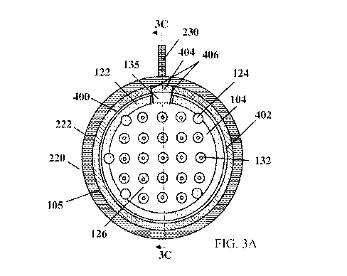
WO 2023/023006 - 17 - PCT/US2022/040393
used. Due to the presence of these bonded regions located radially inwards
from a bonded
perimeter of the membranes, an internal volume formed between the membranes,
once in the
filled configuration, may take the form of a plurality of interconnected
channels 126
corresponding to the unbonded regions of the membranes extending between these
bonded
portions.
[0060] In some instances, the bonded portions of the membranes 102 and 104
may have a
substantially lower membrane permeability due to the bonding process such that
they may be
considered non-diffusive portions of the membranes. This may include both the
bonded
perimeter 122 and the interior bonded portions 124 of the membranes located
radially inwards
from the bonded perimeter. In contrast, the unbonded portions of the
membranes, such as the
channels 126 in the depicted embodiment, may be considered diffusive portions
of the
membranes where the permeabilities of the membranes may be significantly
higher than the non-
diffusive portions, and in some embodiments may be substantially unaltered
from the parent
membrane materials. In addition to the bonded portions of the membranes being
considered non-
diffusive portions of the membranes, portions of the membranes located
radially outward from
the bonded perimeter 122, and that would not be in direct fluid communication
with the resulting
interior volume formed there between, may also be considered a non-diffusive
portion of the
membranes for purposes of this description.
[0061] In some embodiments, after bonding portions of the first and second
membranes
102 and 104 together, one or more through holes 132 may be formed in one or
more of the
bonded portions 122 and 124. For example, a device such as a laser, punch,
cutter, or other
appropriate device may be used to form through holes 132 in one or more of the
bonded portions
of the first membrane 102 and the second membrane 104. In one specific
embodiment, the
through holes may be formed via laser ablation where the laser removes a
bonded portion of the
first and the second membranes while leaving a surrounding bonded portion of
the membranes to
function as a seal between an interior volume formed by the membranes and an
exterior of the
device.
[0062] As shown in Fig. 1A, some bonded portions 124 located within a
specified distance
of the bonded perimeter 122 may not include through hoes 132 such that the
through holes are
disposed radially inward from the bonded perimeter. When the membranes are
bonded to a
frame, the through holes 132 located near the bonded perimeter 122 may cause
stress
concentrations when the device is implanted in vivo, resulting in tearing of
the membrane at the
perimeter 122. Accordingly, while specific dimensions may vary based on the
particular design,
in some embodiments bonded portions located within less than or equal to
approximately 2 mm,
1.75 mm, 1.5 mm, 1.45 mm, or 1.25 mm of the bonded perimeter 122 may not
include through
CA 03229281 2024-02-13
WO 2023/023006 - 18 - PCT/US2022/040393
holes 132. However, embodiments in which different distances both greater than
and less than
those noted above are used are also contemplated.
[0063] In some embodiments, after bonding the membranes together (e.g.
bonding of the
perimeter and/or interior portions of the first membrane and the second), the
first membrane and
the second membrane may be coated with a hydrophilic material and/or subjected
to other
treatments which may not be compatible with the bonding process. This may
include various
high temperature treatments where the bonded membranes may be subjected to
various thermal
treatments which may enhance the bonding of the membranes in some embodiments.
[0064] In some embodiments, a prebonded stack of membranes, such as the
bonded first
and second membranes described above, may be mounted to a frame (see Figs. 2A-
2F).
Alternatively, in some embodiments, a perimeter of a stack of membranes may be
bonded
together and attached to a frame at the same time. In either case, a method
for mounting the
membranes to a frame to provide a desired amount of slack in the membranes
once mounted may
be used. One such embodiment is described in further detail below in relation
to Fig. 4.
[0065] Figs. 2A-2F illustrate an embodiment of a frame 220 of a
macroencapsulation
device. The frame may be a perimeter frame that suspends the membranes within
an opening of
the frame. The frame may extend around at least a portion, and in some
embodiments around an
entire, perimeter of the bonded membranes. The size and shape of the frame may
be selected to
maintain a maximum transverse dimension of the membranes at a smaller second
maximum
transverse (e.g., a width) dimension after mounting relative to a larger first
maximum transverse
dimension of the membranes in a flat configuration prior to mounting. The
maximum transverse
dimension may be measured in a plane in which the planar frame extends. For
example, the
maximum transverse dimension in the depicted embodiment may correspond to a
diameter of the
circular frame placed onto the bonded membranes. However, embodiments in which
frames and
membranes with different shapes and sizes are used are also contemplated.
[0066] As shown in the figures, the frame 220 may be circular in shape,
although it should
be noted that the frame may include any shape that corresponds to the shape of
membranes to be
attached thereto. The frame 220 may include an outer portion 222 and an inner
portion 224. As
shown in Figs. 2E-2F, the outer portion 222 may have a rounded shape that
tapers inward toward
the inner portion 224, forming an inner perimeter surface 226 that extends
around the frame 220.
[0067] The inner perimeter surface 226, or other portion of the frame
configured to
receive the one or more membranes disposed thereon, may include one or more
reservoirs 228
corresponding to through holes, cavities, or other structures configured to
receive a liquid
adhesive there in during a mounting process. For example, the reservoirs may
be arranged
around the inner perimeter of the frame for mounting a perimeter of the
membranes to the frame,
CA 03229281 2024-02-13
WO 2023/023006 - 19 - PCT/US2022/040393
as described in further detail below with respect to Fig. 4. The reservoirs
228 may be equally
spaced around the inner perimeter surface 226, although the disclosure is not
so limiting, and the
reservoirs may be placed in any arrangement around the inner perimeter
surface. The membranes
may have holes or other markings that align with reservoirs 228 to position
the membranes on
the frame during a mounting procedure.
[0068] As shown in Fig. 2F, in some embodiments, the reservoirs may be
tapered holes
that extend through the frame from a first side to a second side of the frame
opposite the first
side. The reservoirs 228 may be tapered such that a diameter D1 of the
reservoir on a first side is
less than a diameter of the reservoir on a second side opposite the first. In
some embodiments,
the reservoirs 228 may not extend entirely through the frame such that the
reservoir may only
have an opening on the first or second side of the frame.
[0069] Going back to Figs. 2A-2D, the frame 220 may include a fill port 230
that extends
from an outer portion 222 to an inner portion 224 of the frame. The fill port
230 may include an
opening 232. The opening 232 may be flush with an adjacent surrounding inner
portion 224 of
the frame such that the opening does not project into the inner portion 224 of
the frame. A
thickness of the inner perimeter surface 226 may increase surrounding the
opening to
accommodate a channel 236 (see Fig. 3C) that extends from the opening through
the fill port.
The fill port 230 may also include a projection 234 that extends outwards from
the outer portion
of the frame. The channel 236 may extend from the opening 232 through the
projection 234 such
that when a membrane is attached to the frame, a desired material may flow
through the fill port
into an internal volume of the membrane.
[0070] Figs. 3A-3D depict one embodiment of a macroencapsulation device
after the
membranes have been mounted to a corresponding frame. Fig. 3A is a front view
of the device
and Fig. 3B is a perspective cross sectional view of a portion of the frame-
membrane interface.
As shown, a bonded membrane including a first and second membrane (only the
top surface of
the second membrane 104 is shown in Figs. 3A-3B) is connected to an inner
perimeter surface
226 of a frame 220. The frame 200 extends around an entire perimeter of the
bonded membranes,
but the disclosure is not so limited and the frame may extend around a portion
of the bonded
membranes in some embodiments. The size and shape of the frame may be selected
to maintain a
maximum transverse dimension of the membranes at a smaller second maximum
transverse
dimension after mounting where the maximum transverse dimension may be
measured in a plane
in which the planar frame extends. For example, the maximum transverse
dimension in the
depicted embodiment may correspond to a diameter of the circular frame placed
onto the bonded
membranes. However, embodiments in which frames and membranes with different
shapes and
sizes are used are also contemplated. Without wishing to be bound by theory,
the ratio of the
CA 03229281 2024-02-13
WO 2023/023006 - 20 - PCT/US2022/040393
first larger maximum transverse dimension prior to mounting and the second
smaller maximum
transverse dimension of the bonded membranes may control the volume of the
internal volume
disposed between the membranes once the membranes are filed with a therapeutic
composition
such as a population of cells.
[0071] As described above with respect to Figs. 1A-1B, the membranes used
to form a
macroencapsulation device may include a bonded perimeter 122 that forms a seal
extending
around an internal volume disposed between the first and second membranes,
which again may
correspond to a single folded over membrane or two separate membranes. In the
depicted
embodiment, the bonded membrane is disposed on the frame 220 such that it
covers the inner
perimeter surface 226 of the frame with an outer perimeter 105 of the bonded
membrane
positioned at or near the outer edge of the inner perimeter surface 226,
exposing only the exterior
portion 222 of the frame. An adhesive layer 400 attaches the bonded membrane
to the inner
perimeter surface 226, or other appropriate portion, of the frame. The
adhesive layer 400 may
extend around the entire inner perimeter surface of the frame, though
embodiments in which
other types of connections, e.g. welding, are used or the membranes and frames
are only bonded
to one another along a portion of the frame or membrane perimeter are also
contemplated.
Appropriate adhesives used may also include UV or heat cured biocompatible
adhesives
including, but not limited to, urethanes, epoxies, or acrylates. An
appropriate adhesive used may
include epoxy-acrylate copolymers such as Epotek and/or Cyberlite.
Alternatively, appropriate
adhesives may include, but not be limited to molten thermoplastics in heat
staking or welding
applications, such as polycarbonates, polypropylenes, polyethylenes, ethylene
vinyl acetate,
polyether(ether ketone), polyvinyl chloride (PVC), polyvinylidene fluoride
(PVDF), polystyrene,
acrylonitrile butanedione styrene (ABS), polyurethane, and/or polymethyl
methacrylate
(PMMA).
[0072] As shown, the bonded perimeter 122 of the membranes is located
radially inward
from the outer perimeter 105 of the bonded membrane. An unbonded portion of
the bonded
membrane or buffer region 402 separates the bonded perimeter 122 and the
adhesive layer 400
that bonds the membrane to the inner perimeter surface 226 of the frame. In
some embodiments,
a transverse dimension (e.g., a width) of the buffer region 402 between the
frame and bonded
portion of a membrane may be greater than or equal to 350 iim, 400 iim, 500
iim, 750 iim, and/or
1 mm. In some embodiments, the transverse dimension (e.g., a width) of the
buffer region 402
may be less than or equal to 2 mm, 1.5 mm, 1.25 mm, 1 mm, 750 iim, and/or 500
iim.
Combinations of the foregoing ranges are contemplated including, for example,
a transverse
dimension (e.g., a width) of the buffer region may be between or equal to
approximately 350 iim
and 750 iim, 400 iim and 750 iim, 350 iim and 2 mm, or other appropriate
combinations of the
CA 03229281 2024-02-13
WO 2023/023006 - 21 - PCT/US2022/040393
foregoing. However, embodiments, with a buffer region with a transverse
dimension between
the adhesive layer 420 and the bonded perimeter 122 that is different from
those noted above are
also envisioned. A liquid adhesive used to bond the membrane to the frame may
have certain
viscosity and wicking characteristics that are balanced with the properties of
the membranes (e.g.
porosity, tortuosity, etc.) to prevent the liquid adhesive from entering the
buffer region 402 when
bonding the membranes to the frame. The adhesive may also have an elastic
modulus greater
than an elastic modulus of the flexible membrane and less than an elastic
modulus of the rigid
frame in some embodiments. As such, the elastic modulus of the
macroencapsulation device may
decrease from the outer frame to the adhesive layer to the membrane, and the
device may
become more flexible proceeding from an exterior portion of the device toward
the center of the
device.
[0073] As a result of the above construction, the buffer region 402 may
reduce, or
substantially eliminate, stress concentrations near the bonded perimeter 122.
This may reduce
the risk of fatigue failure of the membrane. As described above, holes 132 may
not be formed in
the bonded portions 124 located near the bonded perimeter to further reduce
stress concentrations
near the bonded perimeter.
[0074] Fig. 3C shows a side sectional view of the macroencapsulation
device of Fig. 3A
taken along line 3C after the membranes have been mounted to a corresponding
frame and prior
to being filled with a desired material such as a population of cells. As
shown, the device may
include a first membrane 102, a second membrane 104, and a frame 220 that
extends along at
least a portion of the perimeter of the first and second membranes. The device
is illustrated in an
unfilled relaxed state where the extra surface area of the first and second
membranes relative to
the transverse cross-sectional area of the frame within which the membranes
are mounted causes
the bonded membranes to hang below the frame relative to a direction of
gravity due to the
resulting slack in the membranes.
[0075] The membranes 102 and 104 are bonded to the frame 220 on the inner
perimeter
surface 226, as shown on the right side of Fig. 3C. For a portion surrounding
the fill port 230,
however, as shown on the left side of Fig. 3C, the first membrane 102 is
bonded to a first side of
the frame and the second membrane 104 is bonded to a second side of the frame
opposite the first
side. As described in more detail below, flaps 403 and 404 are created in the
first and second
membranes by making cuts 406 in the membranes (see Fig. 3A) and sealing the
flaps 403 and
404 around an opening 323 of the fill port 230. By sealing the flaps around
the opening 323, the
opening of the fill port is now in fluid communication with the internal
volume disposed between
the membranes.
CA 03229281 2024-02-13
WO 2023/023006 - 22 - PCT/US2022/040393
[0076] Due to the bonded portions 124 located within an interior region
of the device,
through holes 132, and other appropriate features having already been formed
on the membranes,
the macroencapsulation device may now be easily filled with a desired
material, such as a
population of cells, with minimal additional processing and handling. The
interior volume may
be filled using a fill port 230, an opening in the perimeter bond, and/or any
other appropriate
method. In either case, after filling a macroencapsulation device with a
desired material, the
internal volume contained between the first and second membranes 102 and 104
may expand
which may take up the slack in the membranes as the membranes are placed under
tension in the
filled configuration due to the internal volume between the membranes
expanding. This may
result in the first and second membranes being deformed such that the
membranes generally
extend in a direction that is approximately parallel to a plane of the frame
220, see Fig. 3D.
Correspondingly, the first and second membranes may now extend outwards from
opposing
surfaces of the frame by approximately equal distance due to this increase in
the internal volume
of the now filled device. In instances where portions 124 of the membranes
have been bonded
together at a location located radially inwards from the frame, the expanded
structure may again
form a plurality of interconnected channels 126.
[0077] A macroencapsulation device may be filled through the fill port
230. For example,
a population of cells, or other desired material, may be flowed into an
interior volume of the
macroencapsulation device formed between the outer membranes of the device.
This may be
accomplished through the fill port 230 or use of a sealable or removable port
extending into the
interior volume. Alternatively, there may be an opening in the perimeter bond
and/or frame of
the macroencapsulation device that may be subsequently sealed. While any
appropriate inlet to
the interior volume may be used to flow material into the interior volume of
the device, the flow
of this material may be controlled in a number of different ways to provide
the desired filling of
the interior volume. For example, in one embodiment, a pressure applied to an
interior volume of
the macroencapsulation device may correspond to a desired amount of tension
present in the
membranes of the device in the filled configuration. Accordingly, filling of
the device may
continue until a predetermined pressure and/or membrane tension threshold has
been reached.
However, any appropriate method for controlling the amount of material flowed
into the interior
volume may also be used as the disclosure is not limited in this fashion. This
may include, for
example, control based on an absolute volume of material flowed into the
interior volume, time
duration for a given flow rate, and/or any other appropriate control method.
[0078] Fig. 4 depicts one embodiment of a process for mounting a frame to
a bonded
membrane. As shown in Fig. 4, a frame 220 is disposed on a support 200. Once
the frame is
secured to the support, bonded membranes 102 and 104 may be disposed on the
frame 200. In
CA 03229281 2024-02-13
WO 2023/023006 - 23 - PCT/US2022/040393
some embodiments, the membranes may be "slack mounted" to the frame. For
example, the
support 200 may include a curved surface 206 to deform the first and second
membrane 102 and
104 from a first maximum transverse dimension before mounting (e.g., where the
membranes are
in a relatively flat planar configuration) to a second maximum transverse
dimension after (e.g.,
where the membrane are deformed to conform to a shape of an underlying support
200). This
concept of controlling an amount of slack in a membrane during mounting with a
frame may
refer to the mounting of at least two or more layers of flexible membranes
(e.g., a first membrane
and a second membrane) under a controlled relaxed tension to form a device
comprising internal
compartments of a defined volume and/or height when filled. In some
embodiments, the curved
surface of the support is a spherical dome as illustrated in Fig. 4. However,
embodiments in
which a support with a different shape is used are also contemplated.
[0079] In some embodiments, the membranes 102, 104 may include holes or
other
markings (not shown) disposed around a perimeter of the membranes that
correspond with
locations of the reservoirs 228 of the frame (see also Fig. 2A-2D) to align
the membranes on the
frame. In some instances, it may be desirable to maintain an orientation
and/or position of a stack
of membranes on a support during mounting to a frame. Accordingly in some
embodiments, and
as shown in the Fig. 4, a vacuum may be applied to one or more non-diffusive
portions of the
first and second membranes to maintain the first and second membranes
proximate the curved
support. For example, the support 200 may include a vacuum chamber 210 that is
connected to a
vacuum source, not shown, to provide a negative pressure. The vacuum chamber
may be fluidly
connected to one or more vacuum holes 212 disposed on a surface of the support
200. While the
vacuum holes may be located at any desired portion of the support's surface,
in some
embodiments, the vacuum holes may be located on portions of the support's
surface where a
corresponding non-diffusive portion of the bonded membranes may be located
including, for
example, the bonded perimeter 122 of the membranes, a portion of the membranes
located
radially outwards from the bonded perimeter, the bonded portions 124 of the
membranes located
within the bonded perimeter, and/or any other appropriate portion of the
membranes. Other
methods of maintaining a position and/or orientation of the membranes relative
to the underlying
support may be used including, but not limited to, mechanical fixation,
clamping, temporary
adhesives, and/or any other appropriate temporary fixation method.
[0080] After positioning the frame 220 and the first and second membranes
102 and 104
in a support, the frame and membranes may undergo a number of different
processes including
bonding in one or more locations. Fig. 4 illustrates a bonding process of the
first and second
membranes to the frame. In certain embodiments, an adhesive, heat staking,
welding (thermal,
ultrasonic, etc.), mechanical fixation, or another appropriate method may be
used to bond the
CA 03229281 2024-02-13
WO 2023/023006 - 24 - PCT/US2022/040393
frame and membranes at a plurality of locations around a circumference of the
frame. This
bonding may either be done sequentially or simultaneously depending on the
manufacturing
process. For example, the frame and membranes may be bonded together at each
of the locations
where the frame includes a reservoir 228 disposed around a circumference of
the inner perimeter
surface 226 of the frame (see Figs. 2A-2D). In the depicted embodiment, a
bonding tool 500 may
be used to create adhesion points between the frame and a portion of the first
and second
membranes at the one or more desired locations. The bonding tool 500 may
correspond to a
combination of a port used to dispense a curable adhesive and a light source
that may be used to
cure the adhesive once positioned on the frame and membranes.
[0081] In one specific embodiment, a bonding tool 500 (e.g., a needle,
syringe) may
deliver a liquid adhesive to a reservoir 228 of the inner perimeter of the
frame 220. The bonding
tool 500 may extend through the membranes 102 and 104 (e.g., by piercing the
membranes or
extending through pre-arranged holes in the membrane) to deposit the liquid
adhesive into the
reservoir 228. The liquid adhesive may then wick through portions of the first
and second
membranes above the reservoir 228. Alternatively, the bonding tool 500 may
apply the liquid
adhesive on a top surface of first membrane and/or second membrane above the
reservoir and the
liquid adhesive may wick through the membranes toward the reservoir 228. In
other
embodiments, the first and second membranes 102 and 104 may be disposed on the
support 200
and the frame then disposed on top of the second membrane. A bonding tool 500
may extend
through the reservoir 228 to deposit a liquid adhesive to a back surface of
the second membrane.
The reservoirs may be tapered in an insertion direction to allow easy
insertion of the bonding
tool. The liquid adhesive may wick through the membranes to bond the membranes
to the frame.
[0082] Once liquid adhesive is applied and has time to wick through the
membranes, the
adhesive may be cured with a light source. Once a bond is formed in a desired
location, the
bonding tool 500 may be moved to an adjacent reservoir 228 (see Figs. 2A-2D)
until a sufficient
number of bonds are formed around the perimeter of the device. As shown in the
figures, the
frame may include equally spaced reservoirs disposed around the perimeter of
the frame,
although the disclosure is not so limited, and nonequal spacing may be used.
As mentioned
above, the duration of bonding and viscosity of the adhesive may be selected
to avoid excessive
wicking of the adhesive into the undesirable portions of the membranes (e.g.,
diffusive portions
and/or buffer region 402). In some embodiments, the viscosity of the adhesive
may be greater
than or equal to approximately 100 cP, 200 cP, and/or 300 cP. The viscosity
may also be less
than or equal to approximately 1000cP, 750cP, and/or 500 cP. Combinations of
the foregoing are
contemplated including, for example, the viscosity may be between or equal to
100 cP and 1000
cP, or more preferably between 100 cP and 500 cP. Other viscosities both
greater than and less
CA 03229281 2024-02-13
WO 2023/023006 - 25 - PCT/US2022/040393
than those noted above are also envisioned. The duration of bonding of the
adhesive may be
greater than or equal to approximately 5 seconds 10 seconds, and/or 15
seconds. The duration of
bonding may also be less than or equal to approximately 60 seconds, 30 seconds
and/or 20
seconds. Combinations of the foregoing durations are contemplated including,
for example, a
duration of bonding that is between or equal to 5 seconds and 60 seconds, or
more preferably
between 10 seconds and 30 seconds. Other durations both greater than and less
than those noted
above are also contemplated. Additionally, while a particular bonding method
has been described
other appropriate types of bonding may be used as noted above.
[0083] While the use of a liquid adhesive is described above, other
appropriate types of
bonding techniques such as heat staking, ultrasonic welding, laser welding, or
any other
appropriate bonding technique may also be used as the disclosure is not so
limited.
[0084] The bonding locations may be predetermined such that an associated
processor
(not shown) may be configured to control the bonding tool 500 such that it is
properly positioned
relative to each reservoir 228 of the frame during the separate bonding
procedures to form the
bonds around the device perimeter. In some embodiments, the bonding tool 500
may include one
or more sensors to detect the reservoir sites, such as through visual
tracking, magnetic sensing, or
other appropriate robotic system targeting methods. Thus the bonding tool and
or support may
include one or more sensors 110 distributed around a surface of the lower
portion of the fixture
106 may communicate signals to the processor to implement feedback control of
the bonding
process.
[0085] After this initial fixation of the membranes to the frame,
additional processing of
the mounted frame and membranes may then be done including, for example,
placing additional
adhesive between the mounted frame and membranes to improve a bond there
between. If the
membrane was mounted on top of the frame in the initial fixation step (as
shown in Fig. 4) then
the device may stay fixed in support 200. If the frame was mounted on top of
the membrane
(with bonding tool extending through the reservoir to mount a back surface of
the second
membrane to the frame, as mentioned above), the macroencapsulation device
including the frame
and mounted membranes may be removed from the curved support and resecured in
the support
in an inverted position (i.e., with the membrane on top of the frame). The
device may undergo
another processing step that applies an adhesive layer 400 (see Figs. 3A-3B)
to further bond the
membrane to the inner perimeter surface of the frame. A bonding tool may apply
adhesive in
sections between each reservoir 228, applying and curing adhesive in each
section before moving
onto an adjacent section, until the entire perimeter is bonded. Any wrinkles
or creases in the
membrane may be smoothed during the bonding process as well. As mentioned
above, the
duration of bonding and viscosity of the adhesive may be selected to avoid
excessive wicking of
CA 03229281 2024-02-13
WO 2023/023006 - 26 - PCT/US2022/040393
the adhesive into the undesirable portions of the membranes (e.g., diffusive
portions and/or
buffer region 402) such that the seal and buffer region of the bonded
membranes are disposed
radially inwards relative to both the frame and the adhesive, or other form of
connection,
bonding the membranes to the frame.
[0086] After the frame is bonded to the membranes, the device may be
removed from the
support. To fill the interior volume of the device (e.g., with cells),
portions of the first and second
membranes surrounding the fill port 230 may be positioned on opposite sides of
the frame and
sealed around the opening 323 of the fill port 320. Referring back to Fig. 3A,
starting on a first
side of the frame with the membranes positioned on top of the frame, portions
of the first and
second membrane over the fill port area may be separated. In embodiments with
an unfused
portion 135 of the perimeter bond 122, the membranes may only need to be
separated to up to the
buffer region 402; however, in embodiments without an unfused portion 135
(i.e., the perimeter
bond extends around the entire perimeter of the membrane), then the membranes
may need to be
separated past the perimeter bond. After the membranes are sufficiently
separated, cuts 406 may
be created in the first and second membranes on each side of the fill port
230. The cuts 406 may
be perpendicular to the adhesive seal 400 and extend from the membrane
perimeter 105 to the
perimeter bond 122. The cuts 406 create a first flap 403 in the first membrane
and a second flap
404 in the second membrane 104 opposite from the first flap. The second flap
404 is then folded
back onto the top surface of the second membrane 104 to reveal the first flap
403 (see dotted fold
line between cuts 406 in Fig. 3A). The first flap 403 of the first membrane is
then pushed inward,
passing the interior portion 224 of the frame such that it protrudes from a
second side of the
frame opposite the first side. The first flap 403 is then pulled onto the
inner perimeter surface 226
on the second side of the frame, smoothing the flap to the make the flap rest
flush on a first
upwards oriented surface of the frame. The second flap 404 is pulled over the
first side of the
frame and smoothed to the make the flap rest flush on a second downwards
oriented surface of
the frame opposite from the first surface. An adhesive is then applied to the
flaps and cured to
seal the flaps around the fill port opening, though other bonding and sealing
methods may also be
used.
[0087] In the above embodiments, a frame is connected to an exterior
surface of a first
membrane 102 opposite from a second membrane 104. However, embodiments in
which a frame
220 is disposed between the first membrane 102 and second membrane 104 are
also
contemplated. In such an embodiment, portions of the first and second
membranes extending
radially outward from a bond 122 extending along a perimeter of the membranes
may be opened
and the frame may be positioned between the membranes at a location disposed
radially outward
from the perimeter bond of the membranes. The first and second membranes may
then be bonded
CA 03229281 2024-02-13
WO 2023/023006 - 27 - PCT/US2022/040393
to the frame using any appropriate bonding method as described previously.
While a particular
angular orientation of the frame, membranes, and underlying support has been
depicted in the
figures, it should be understood that any appropriate orientation of these
components may be
used as the disclosure is not limited in this fashion. In either case, the
frame may still function to
maintain a desired transverse dimension of the membranes once removed from the
underlying
support.
[0088] Example: In vivo fatigue testing
[0089] A Gottingen minipigs was used to study the mechanics of a
macroencapsulation
device. Designs of macroencapsulation devices that were tested included
designs as described
above as well as prior designs. The prior designs included bonded membranes
mounted to a
perimeter frame such that a seal perimeter of the membranes was disposed on
the frame (i.e.,
there was no gap between an inner perimeter of the frame and the seal
perimeter). Testing results
of the prior designs, showing fatigue failure at the frame interface due to
stress concentrations at
these areas, motivated new designs of the macroencapsulation devices with
stress relief zones at
the frame interface.
[0090] In comparison to the perimeter frame, which has been tuned to
allow only a small
amount of flexibility, the region of the device comprised primarily of
membrane is significantly
more flexible, leading to a mechanical transition zone between the frame and
membrane that is
coupled with adhesive. In silico and nonclinical studies of prototype devices
identified this area
as the most likely point of fatigue failure in the device, which was revised
in a subsequent
version by adding a stress relief zone as described herein to strengthen the
interface. To
interrogate the mechanical durability of the device at the frame-membrane
interface, a fatigue
test was developed to accelerate the functional duration of testing to time
points beyond the
duration of the proposed nonclinical studies.
[0091] Example: Ex vivo fatigue testing
[0092] Ex vivo fatigue testing was done to simulate forces exerted by
myofibroblast-
anchored abdominal contraction within the center mesh of a macroencapsulation
device by
developing a biphasic, fully reversed loading strategy wherein a clamped
membrane is cycled
symmetrically through displacement extremes. During testing, the device frame
was secured
between two parallel aluminum plates as the center-mesh clamp was actuated in
the axial
direction, applying cyclic tension to the mesh defined by a relevant
physiological load or, in the
case of design exploration, an elevated load to enable rapid iterative
feedback.
[0093] Figs. 5A-5B depicts an embodiment of a prior design of a
macroencapsulation
device 300 after fatigue testing. In such an embodiment, the membrane 302 was
mounted to the
frame 306 such that the seal perimeter 304 was arranged at the frame
interface. The device 300
CA 03229281 2024-02-13
WO 2023/023006 - 28 - PCT/US2022/040393
also includes a fill port 308 that extends from the frame perimeter into the
membranes. As shown
in Fig. 5A, the membrane 302 has ruptured from the frame 306 at the seal
perimeter 304 due to
stress concentrations at the interface. Fatigue testing on prior designs and
new designs showed
that the prior design failed after approximately 10000 cycles, whereas the new
designs failed
after more than 30000 cycles. Fig. 5B shows the fill port interface and an
enlarged view of a tear
at the fill port interface caused by high stress concentrations. Internal fill
port damage was
observed in 52% of devices. New designs without internal fill ports resulted
in improved fatigue
life as elaborated on below.
[0094] Example: Failure Mode Investigation
[0095] Tests were conducted to investigate potential causes of membrane
failure. Results
showed that failure of the devices was caused primarily by adhesive
irregularity and lack of
concentricity
[0096] A. Manufacturability: Adhesive Application
[0097] One cause of device failure at the frame interface may be due to
poor application
of the adhesive by trainees. Devices made by experts may have subtle
irregularities, while
devices made by trainees may have gross irregularities. Test results confirmed
that devices
having gross irregularities failed early, with less than 1000 cycled to
failure, compared with
approximately 6000 cycles to failure with devices having subtle
irregularities. Fatigue testing of
the devices also showed failure of the membranes that matched failure of the
devices tested in
vivo. Prior designs required tight mounting tolerances and precise adhesive
application to reduce
risk of failure, which is difficult to automate and requires manufacturing my
highly skilled
individuals. The updated designs with stress relief zones and manufacturing
methods as
described above provide higher tolerances for adhesive application, which
allows for
manufacturing by lower skill level trainees or automation (e.g., using
reservoirs around perimeter
of frame as described above). For example, the addition of the reservoirs
around the frame
perimeter provide a reliable method to reduce the number of gross incursions
which greatly
affect the number of cycles to crack formation on the devices. Devices with
gross incursions
formed cracks at approximately 1000 cycles whereas devices with no incursions
formed cracks at
more than 7000 cycles. The fatigue testing methodology was developed
specifically to mimic the
forces exerted by myofibroblast-anchored abdominal contraction within the
center mesh by
developing a biphasic, fully reversed loading strategy wherein a clamped
membrane was cycled
symmetrically through displacement extremes. During testing, the device frame
was secured
between two parallel aluminum plates and a central portion of the membrane was
clamped to a
loading system, such as an Instron fatigue test fixture, to apply axial
displacements to the
membranes relative to the frame to apply cyclic tension to the membranes
defined by a relevant
CA 03229281 2024-02-13
WO 2023/023006 - 29 - PCT/US2022/040393
physiological load or, in the case of design exploration, an elevated load to
enable rapid iterative
feedback. The cyclic loading forces applied during these fatigue tests varied
between 30N and
45N depending on the specific fixture and frame being tested. By providing the
reservoirs, the
number of gross incursions in the new devices was approximately 5 whereas the
prior devices
had almost 20 gross incursions.
[0098] B. Adhesive Quality
[0099] Tests were conducted to determine whether the quality of adhesive
used may
affect the frame interface. For example, it was investigated whether the
adhesive degrading or
changing properties affects the interface and if there were advantages to
using an alternative
flexible adhesive (e.g., Cyberlite). In the first phase of testing, dogbone
shapes of the regular
adhesive (Epotek 0G198-54) and Cyberlite were tensile tested at 0, 3, 6, 9 and
12 months to
determine the tensile strength at fracture. Results showed that Epotek was
stable with no
apparent embrittlement over time. For example, the adhesive had consistent
tensile strength at
break of approximately 20-25 MPa when tested at each time interval. The Epotek
also showed a
stable Young's modulus of approximately 1000 to 1250 MPa over 12 months. The
Cyberlite, on
the other hand, showed weakening over time, with a tensile strength of
approximately 10 MPa at
0 months and less than 5 MPa at 12 months. The Yong's modulus of Cyberlite
also decreased
from approximately 500 MPa to approximately 100 MPa over 12 months.
[00100] Second phase of testing including fatigue testing the new designs
of
macroencapsulation devices (e.g., with stress relief zone) with different
adhesive combinations:
full Epotek, Cyberlute / Epotek combination, and full Cyberlite. Results
showed that devices
with full Eportek had over 105 cycles to failure, Cyberlite / Epotek
combination had 104 cycles to
failure, and full Cyberlite had the lowest with less than 104 cycles to
failure.
[00101] Results showed that relocation of the seal perimeter improves
manufacturability
and fatigue resistance of the device. For example, the new design reduces
dependence on an
operator by increasing tolerances, improves concentricity and adhesion
uniformity, and reduces
the complexity of visual inspection. Based on the presented testing of the
current devices, the
expected fatigue life of the device is approximately five years of continuous
coughing, estimated
to represent a peak load on the device at 11.6 N for 87,600 cycles.
[00102] While the present teachings have been described in conjunction
with various
embodiments and examples, it is not intended that the present teachings be
limited to such
embodiments or examples. On the contrary, the present teachings encompass
various
alternatives, modifications, and equivalents, as will be appreciated by those
of skill in the art.
Accordingly, the foregoing description and drawings are by way of example
only.