Note: Descriptions are shown in the official language in which they were submitted.
MEDICAL ENDOSCOPE SYSTEM
BACKGROUND OF THE INVENTION
FIELD OF THE INVENTION
[0001] The present disclosure relates to a medical endoscope system and, more
particularly, to a medical endoscope system with a simplified operating
method, so
that a user can be free from the burden of holding a sheath device and an
optical
sensing device of the medical endoscope system with separate hands at the same
time.
DESCRIPTION OF THE PRIOR ART
[0002] In a conventional medical endoscope system, although an optical sensing
device (i.e., endoscope device) is disposed to extend within a sheath device,
the
two devices are actually separate, and the optical sensing device is not fixed
to the
sheath device. The conventional arrangement of the medical endoscope system
thus requires a user (for example, a medical professional) to separately hold
and
operate the optical sensing device and the sheath device with two hands.
During
surgery, the user has to hold and operate the sheath device with one hand,
while
using the other hand to hold and operate the optical sensing device disposed
within
the sheath device. Such operating method greatly increases the difficulty for
users
to operate a conventional medical endoscope system. It is difficult for the
user to
precisely control the sheath device and other medical devices in the sheath
device
altogether while observing through the optical sensing device. In view of
this, it is
necessary to provide a medical endoscope system with a simplified operating
1
CA 03229547 2024- 2- 20
method, so that the user can be free from the burden of holding a sheath
device
and an optical sensing device of the medical endoscope system with separate
hands at the same time.
SUMMARY OF THE INVENTION
[0003] To remedy the aforesaid drawbacks of the prior art, it is an objective
of the
present disclosure to provide a medical endoscope system with a simplified
operating method, so that the user can be free from the burden of holding a
sheath
device and an optical sensing device of the medical endoscope system with
separate hands at the same time.
[0004] Based on the foregoing idea, the present disclosure provides a medical
endoscope system, comprising: a sheath device having an end portion; and an
optical sensing device disposed to extend within the sheath device and fixed
to the
end portion, wherein the optical sensing device has a transmission portion and
transmits an optical signal received by the optical sensing device through the
transmission portion.
[0005] In a preferred embodiment of the present disclosure, the end portion of
the
sheath device is a transparent tubular element.
[0006] In a preferred embodiment of the present disclosure, the medical
endoscope system further comprises: a liquid passage portion disposed to
extend
within the sheath device and having a passage port, wherein the passage port
of
the liquid passage portion is disposed at the end portion of the sheath
device, and
the medical endoscope system allows a liquid to flow out of the end portion
along
the liquid passage portion.
2
CA 03229547 2024- 2- 20
[0007] In a preferred embodiment of the present disclosure, the optical
sensing
device has an optical sensing portion, and the medical endoscope system allows
the liquid to flow to the end portion to come into contact with the optical
sensing
portion.
[0008] In a preferred embodiment of the present disclosure, the optical
sensing
portion is a CMOS sensor.
[0009] In a preferred embodiment of the present disclosure, the optical
sensing
device has an illumination portion disposed around the optical sensing
portion.
[0010] In a preferred embodiment of the present disclosure, the optical
sensing
device comprises: a first optical sensing portion disposed at the end portion
and
facing a first direction to receive a first optical signal; and a second
optical sensing
portion disposed at the end portion and facing a second direction to receive a
second optical signal, wherein the first direction is not parallel to the
second
direction.
[0011]
In a preferred embodiment of the present disclosure, the sheath device
has a first fixing mechanism disposed at a control end portion of the sheath
device;
the optical sensing device has a second fixing mechanism, and the optical
sensing
device is fixed to the end portion by causing the second fixing mechanism to
be
connected and fixed to the first fixing mechanism; and the second fixing
mechanism
is detachably connected and fixed to the first fixing mechanism.
[0012] In a preferred embodiment of the present disclosure, the sheath device
has a fixing portion disposed at the end portion, and the optical sensing
device is
detachably fixed to the fixing portion.
[0013] In a preferred embodiment of the present disclosure, the fixing portion
is a
magnet.
3
CA 03229547 2024- 2- 20
[0014] In a preferred embodiment of the present disclosure, the sheath device
has a groove disposed to extend on an inner wall surface of the sheath device,
wherein the optical sensing portion is connected to the groove and is movable
along
the groove.
[0015] In a preferred embodiment of the present disclosure, the end portion
comprises an open end portion, and a retraction distance is provided between
the
optical sensing device and the open end portion.
[0016] In a preferred embodiment of the present disclosure, the medical
endoscope system further comprises an electrocautery device fixed to an
outside
surface of the end portion.
[0017] In a preferred embodiment of the present disclosure, the medical
endoscope system further comprises an electrocautery device movably disposed
to extend within the sheath device, wherein the electrocautery device has a
fixing
mechanism and an electrocautery portion, and the electrocautery device is
detachably fixed to the end portion of the sheath device through the fixing
mechanism, so that the electrocautery portion is exposed outside the sheath
device.
[0018] In a preferred embodiment of the present disclosure, the medical
endoscope system further comprises a shutter device movably disposed to extend
within the sheath device, wherein the shutter device has a shutter portion,
and the
shutter device shuts an opening portion of the end portion through the shutter
portion.
[0019] In a preferred embodiment of the present disclosure, the shutter
portion is
an inflatable element.
4
CA 03229547 2024- 2- 20
[0020] In a preferred embodiment of the present disclosure, the medical
endoscope system further comprises a surgical device disposed within the
sheath
device.
[0021] The various aspects of the present disclosure stated above, together
with
other aspects of the present disclosure, will be clarified further hereinafter
based on
the following detailed description of the non-restrictive embodiments and
their
accompanying drawings.
BRIEF DESCRIPTION OF THE DRAWINGS
[0022] FIG. 1A is a schematic view showing the structure of a medical
endoscope
system according to an embodiment of the present disclosure.
[0023] FIG. 1B is a schematic view of the medical endoscope system according
to an embodiment of the present disclosure.
[0024] FIG. 2 is a schematic view of the medical endoscope system according to
an embodiment of the present disclosure.
[0025] FIG. 3 is a schematic view of the medical endoscope system according to
an embodiment of the present disclosure.
[0026] FIG. 4A is a schematic view of the medical endoscope system according
to an embodiment of the present disclosure.
[0027] FIG. 4B is a schematic view of the medical endoscope system according
to an embodiment of the present disclosure.
[0028] FIG. 5A is a schematic view of the medical endoscope system according
to an embodiment of the present disclosure.
[0029] FIG. 5B is a schematic view of the medical endoscope system according
to an embodiment of the present disclosure.
CA 03229547 2024- 2- 20
[0030] FIG. 6 is a schematic view of the medical endoscope system according to
an embodiment of the present disclosure.
[0031] FIG. 7 is a schematic view of the medical endoscope system according to
an embodiment of the present disclosure.
[0032] FIG. 8A is a schematic view of the medical endoscope system according
to an embodiment of the present disclosure.
[0033] FIG. 8B is a schematic view of the medical endoscope system according
to an embodiment of the present disclosure.
DETAILED DESCRIPTION OF THE EMBODIMENTS
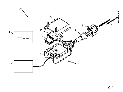
[0034] FIG. 1A is a schematic view showing the structure of a medical
endoscope
system according to an embodiment of the present disclosure. In the embodiment
illustrated in FIG. 1A, a medical endoscope system 100 comprises a sheath
device
110 and an optical sensing device 120. The sheath device 110 has an end
portion
112, and the optical sensing device 120 comprises a transmission portion 122
and
an optical sensing portion 124. The optical sensing device 120 is disposed to
extend
within the sheath device 110 (the description "disposed to extend" means that
the
optical sensing device 120 extends within the sheath device 110 along the
length
direction of the sheath device 110; for example, the optical sensing portion
124 of
the optical sensing device 120 can be disposed at the end portion 112 of the
sheath
device 110, while the transmission portion 122 of the optical sensing device
120
can extend from the optical sensing portion 124 to the other end of the sheath
device 110 along the internal portion of the sheath device 110), and the
optical
sensing device 120 is fixed to the end portion 112. Thus, a user (for example,
a
medical professional) can hold and operate the medical endoscope system 100 at
6
CA 03229547 2024- 2- 20
the same time, without having to hold or operate the sheath device 110 and the
optical sensing device 120 with two separate hands; as a result, the
difficulty in
operating the medical endoscope system 10 can be significantly reduced. In one
embodiment, another surgical device 130 (including, for example, a medical
clamping device or a medical cutting device, but not limited thereto) is
disposed
within the sheath device 110 to perform medical treatment (including, for
example,
a minor surgery, but not limited thereto) on a target lesion in the human
body. In
particular, the surgical device 130 is connected to the sheath device 110
and/or
fixed within it as needed, or the surgical device 130 can be movably disposed
within
the sheath device 110 as needed. Preferably, in the medical endoscope system
110, the optical sensing portion 124 of the optical sensing device 120 is
fixed to the
end portion 112 of the sheath device 110. The optical sensing device 120 can
receive an optical signal through the optical sensing portion 124, and can
transmit
the optical signal through the transmission portion 122. For example, when the
end
portion 112 of the sheath device 110 is placed at a target lesion in the human
body,
the optical sensing portion 124 at the end portion 112 can receive (or detect)
an
optical signal of the target lesion, and then transmit the optical signal to a
display
device outside the human body. As a result, the user can observe the images of
the
target lesion displayed on the display device. Preferably, the end portion 112
of the
sheath device 110 can be a transparent tubular element. For example, the
sheath
device 110 is a transparent tubular device. As a result, the problem that the
sheath
device 110 may block the field of view of the optical sensing portion 124 can
be
avoided. In one embodiment, the optical sensing portion 124 of the optical
sensing
device 120 is a CMOS (complementary metal oxide semiconductor) sensor.
Nevertheless, it should be understood that the optical sensing portion 124 of
the
7
CA 03229547 2024- 2- 20
optical sensing device 120 is not limited to a CMOS sensor, and it can be a
sensor
of other types as needed. In one embodiment, the optical sensing device 120
can
have an illumination portion connected to the optical sensing portion 124 and
provide illumination for the view of the surgical field in front of the
optical sensing
portion 124. The illumination portion can be, for example, an LED (light-
emitting
diode) device. Preferably, the illumination portion is disposed around the
optical
sensing portion 124.
[0035] Referring to FIG. 1B, there is shown a schematic view of the medical
endoscope system according to an embodiment of the present disclosure. In the
embodiment illustrated in FIG. 1B, a medical endoscope system 100B comprises a
sheath device 110B and an optical sensing device 120B. The sheath device 110B
has an end portion 112B, a control end portion 114B and a first fixing
mechanism
116B, and the first fixing mechanism 116B is disposed at the control end
portion
114B of the sheath device 110B. The optical sensing device 120B comprises a
second fixing mechanism 128B, a transmission portion 122B and an optical
sensing
portion (may be referred to as the "primary optical sensing portion") 124B.
The
second fixing mechanism 128B is connected to the transmission portion 122B,
and
the transmission portion 122B is connected to the optical sensing portion
124B. The
optical sensing device 120B is disposed to extend within the sheath device
110B,
(the description "disposed to extend" means that the optical sensing device
120B
extends within the sheath device 110B along the length direction of the sheath
device 110B; for example, the optical sensing portion 124B of the optical
sensing
device 120B can be disposed at the end portion 112B of the sheath device 110B,
while the transmission portion 122B of the optical sensing device 120B can
extend
from the optical sensing portion 124B to the control end portion 114B of the
sheath
8
CA 03229547 2024- 2- 20
device 110B). Preferably, the second fixing mechanism 128B of the optical
sensing
device 120B is connected and fixed to the first fixing mechanism 116B, and
thus
the optical sensing device 120B is fixed to the end portion 112B of the sheath
device
110B. Therefore, the user (for example, a medical professional) can hold and
operate the medical endoscope system 100B at the same time, without having to
hold or operate the sheath device 110B and the optical sensing device 120B
with
two separate hands; the difficulty in operating the medical endoscope system
100B
can thus be significantly reduced.
[0036] It should be understood that the first fixing mechanism 116B and the
second fixing mechanism 128B can be, including but not limited to, a snap-
engaging
mechanism, engaging mechanism, screwing mechanism, binding mechanism, or
adhesion mechanism as needed. Therefore, the second fixing mechanism 128B
can be connected and fixed to the first fixing mechanism 116B by means of snap-
engagement, engagement, screwing, binding, or adhesion etc. as needed.
Preferably, the second fixing mechanism 128B is detachably connected and fixed
to the first fixing mechanism 116B. Preferably, the optical sensing device
120B
being fixed to the end portion 112B of the sheath device 110B, as stated
above,
shall mean that the optical sensing portion 124B of the optical sensing device
120B
is fixed to the end portion 112B of the sheath device 110B. Preferably, the
optical
sensing device 120B being fixed to the end portion 112B of the sheath device
110B
shall mean that the optical sensing device 120B (or the optical sensing
portion 124B
of the optical sensing device 120B) is fixed to the end portion 112B of the
sheath
device 110B, wherein the optical sensing device 120B (or the optical sensing
portion 124B of the optical sensing device 120B) is not necessarily connected
to
the end portion 112B of the sheath device 110B directly. Preferably, the
external
9
CA 03229547 2024- 2- 20
portion (or housing) of the transmission portion 122B is made of a hard
material. As
a result, regardless of whether the optical sensing portion 124B is connected
to the
end portion 112B (for example, through a mechanism such as a magnet, to be
explained in details), when the second fixing mechanism 128B of the optical
sensing
device 120B is connected and fixed to the first fixing mechanism 116B, the
optical
sensing portion 124B of the optical sensing device 120B remains driven by the
transmission portion 122B and thus fixed to the end portion 112B of the sheath
device 110B).
[0037] Referring to FIG. 2, there is shown a schematic view of the medical
endoscope system according to an embodiment of the present disclosure. In the
embodiment illustrated in FIG. 2, a sheath device 210 of a medical endoscope
system 200 has a groove 214, and the groove 214 is disposed to extend on an
inner
wall surface of the sheath device 210 (the description "disposed to extend"
means
that the groove 214 extends within the sheath device 210 along the length
direction
of the sheath device 210), wherein the optical sensing portion 224 is
connected to
the groove 214 and is movable (or slidable) along the groove 214. As a result,
the
user can place the optical sensing device of the medical endoscope system 200
into the sheath device 210 along the groove 214 as needed, or can remove the
optical sensing device from the sheath device 210 along the groove 214 as
needed.
[0038] In one embodiment, the sheath device can have a fixing portion, and the
fixing portion is disposed at the end portion of the sheath device, wherein
the optical
sensing device is detachably fixed to the fixing portion. For example,
referring to
FIG. 3, there is shown a schematic view of the medical endoscope system
according to an embodiment of the present disclosure. In the embodiment
illustrated
in FIG. 3, a sheath device 310 of a medical endoscope system 300 has a fixing
CA 03229547 2024- 2- 20
portion 316, and the fixing portion 316 is disposed on the inner wall surface
at an
end portion 312 of the sheath device 310. As a result, the optical sensing
device of
the medical endoscope system 300 can be fixed to the end portion 312 by the
user
as needed, or can be removed from the optical sensing device from the end
portion
312 as needed. Preferably, the fixing portion 316 is a magnet, and the fixing
portion
316 and an optical sensing portion 324 of the optical sensing device can be
detachably fixed to each other by a magnetic force, so that the optical
sensing
portion 324 of the optical sensing device is fixed to the end portion 312.
[0039] Referring to FIG. 4A and FIG. 4B, there are shown schematic views of
the
medical endoscope system according to an embodiment of the present disclosure.
In the embodiment illustrated in FIG. 4A and FIG. 4B, a medical endoscope
system
400 further comprises a shutter device 430, and the shutter device 430 is
movably
disposed to extend within a sheath device 410 (the description "disposed to
extend"
means that the shutter device 430 extends within the sheath device 410 along
the
length direction of the sheath device 410). The user can place the shutter
device
430 into the sheath device 410 along the length direction thereof as needed,
or can
remove the shutter device 430 from the sheath device 410 along the length
direction
thereof as needed. The shutter device 430 has a shutter portion 432, and the
user
can shut an opening portion 418 of the sheath device 410 (the opening portion
418
is located at an end portion 412 of the sheath device 410) through the shutter
portion 432 while placing the medical endoscope system 400 into the patient's
body.
In this way, damage to human tissue caused by the opening portion 418 of the
sheath device 410 can be prevented. Preferably, the volume of the shutter
portion
432 can be controlled by the user. In this way, the volume of the shutter
portion 432
can be reduced before moving the shutter device 430 along the sheath device
410;
11
CA 03229547 2024- 2- 20
this can help avoid moving the optical sensing device (in particular an
optical
sensing portion 424 of the optical sensing device) to a wrong position, or
avoid
damaging the optical sensing portion 424 during the movement of the shutter
portion 432. In one embodiment, the shutter portion 432 is an inflatable
element,
and the user can inflate the shutter portion 432 to increase the volume of the
shutter
portion 432 as needed (see FIG. 4A), or can deflate the shutter portion 432 to
reduce the volume of the shutter portion 432 as needed (see FIG. 4B).
Preferably,
the shutter portion 432 can be configured to have a specific shape (for
example,
the shutter portion 432 may have a notch portion 434, and the notch portion
434
will not come into contact with the optical sensing portion 424 when the
shutter
portion 432 is inflated), thereby ensuring the shutter portion 432 does not
press
against the optical sensing device (in particular the optical sensing portion
424 of
the optical sensing device) when it is inflated. In one embodiment, to
simplify the
operating process or to lower the manufacturing cost of the shutter device,
the
shutter portion of the shutter device can have a fixed shape, and can be made
of,
for example, a plastic material, but is not limited thereto. In one
embodiment, since
the optical sensing device and the sheath device can be separated from each
other
as needed (i.e., the optical sensing device is detachably fixed to the sheath
device),
the shutter portion may not have a notch portion. When using the shutter
device,
the user does not have to mount the optical sensing device on the sheath
device,
and thus, the shutter device will not come into contact with or press against
the
optical sensing device.
[0040] Referring to FIG. 5A and FIG. 5B, there are shown schematic views of
the
medical endoscope system according to an embodiment of the present disclosure.
In the embodiment illustrated in FIG. 5A and FIG. 5B, a medical endoscope
system
12
CA 03229547 2024- 2- 20
500 further comprises an electrocautery device 540. The electrocautery device
540
is movably disposed to extend within a sheath device 510 (the description
"disposed
to extend" means that the electrocautery device 540 extends within the sheath
device 510 along the length direction of the sheath device 510 the). The user
can
place the electrocautery device 540 into the sheath device 510 along the
length
direction thereof as needed, or can remove the electrocautery device 540 from
the
sheath device 510 along the length direction thereof as needed. The
electrocautery
device 540 has a fixing mechanism 542 and an electrocautery portion 544. The
electrocautery device 540 is detachably fixed to an end portion 512 of the
sheath
device 510 through the fixing mechanism 542, and the electrocautery portion
544
is exposed outside the sheath device 510. As a result, the user can use the
electrocautery portion 544 of the electrocautery device 540 to perform
electrocautery on the target tissue (for example, electrocautery can be
applied to
target blood vessels or tissues to stop bleeding). In the embodiment
illustrated in
FIG. 5A and FIG. 5B, the fixing mechanism 542 is a hook-shaped mechanism; the
user can have the fixing mechanism 542 fixed to the opening portion of the
sheath
device 510 by hooking, and have the electrocautery portion 544 exposed outside
the sheath device 510. Nevertheless, it should be understood that the fixing
mechanism is not limited to a hook-shaped mechanism, and the fixing mechanism
may be a mechanism in other shapes as along as it can provide a fixing
function.
Referring to FIG. 6, there is shown a schematic view of the medical endoscope
system according to an embodiment of the present disclosure. In the embodiment
illustrated in FIG. 6, a medical endoscope system 600 further comprises an
electrocautery device 640, and the electrocautery device 640 is fixed to the
outside
surface of an end portion 612 of a sheath device 610. The user can use the
13
CA 03229547 2024- 2- 20
electrocautery device 640 to perform electrocautery on the target tissue (for
example, electrocautery can be applied to target blood vessels or tissues to
stop
bleeding). Preferably, the electrocautery device 640 is an electrode that
realizes
electrocautery through a circuit 642 to which power is supplied. It should be
understood that when the electrocautery device 640 is composed of electrodes,
the
number of the electrodes is subject to the user's needs; for example, the
electrocautery device 640 may be composed of one electrode, two electrodes
(dual
electrodes), or three electrodes, but is not limited thereto.
[0041] Referring to FIG. 7, there is shown a schematic view of the medical
endoscope system according to an embodiment of the present disclosure. In the
embodiment illustrated in FIG. 7, a medical endoscope system 700 further
comprises a liquid passage portion 750 disposed to extend within a sheath
device
710 (the description "disposed to extend" means that the liquid passage
portion 750
extends along the length direction of the sheath device 710 within the sheath
device
710), and the liquid passage portion 750 has a passage port 752. The passage
port
752 of the liquid passage portion 750 is disposed at an end portion of the
sheath
device 710, and the user can control the medical endoscope system 700 in a way
that allows a liquid (for example, water) to flow out of the end portion of
the sheath
device 710 along the liquid passage portion 750, so as to irrigate the target
tissue
or wash away a foreign object. In one embodiment, the passage port 752 is
disposed close to the optical sensing portions 723, 724 of an optical sensing
device
720. Therefore, the user can control the medical endoscope system 700 in a way
that allows a liquid (for example, water) to flow along the liquid passage
portion 750
to the optical sensing portions 723, 724 of the optical sensing device 720 to
irrigate
the target tissue.
14
CA 03229547 2024- 2- 20
[0042] Referring to FIG. 8A, there is shown a schematic view of the medical
endoscope system according to an embodiment of the present disclosure. In the
embodiment illustrated in FIG. 8A, an optical sensing portion (may be referred
to as
the "primary optical sensing portion") 820 of the optical sensing device has a
first
optical sensing portion 823 and a second optical sensing portion 825. The
first
optical sensing portion 823 is disposed at an end portion 812 of a sheath
device
810 and facing a first direction 910 to receive a first optical signal. The
second
optical sensing portion 825 is disposed at the end portion 812 of the sheath
device
810 and facing a second direction 920 to receive a second optical signal. The
first
direction 910 is not parallel to the second direction 920; thus, the field of
view of the
first optical sensing portion 823 and the field of view of the second optical
sensing
portion 825 do not overlap with each other but gradually move apart. In this
way,
image data from different angles can be obtained, so that images with more
different
fields of view can be generated. In one embodiment, the end portion 812 of the
sheath device 810 comprises an open end portion 813, and there is a retraction
distance 930 between the optical sensing portions 823, 825 and the open end
portion 813. It should be understood that, depending on the different needs,
there
may not be a retraction distance between the optical sensing portions 823, 825
and
the open end portion 813; instead, the optical sensing portions 823, 825 can
be
disposed at the open end portion 813, or the optical sensing portions 823, 825
can
be disposed slightly protruded from the open end portion 813.
[0043] Referring to FIG. 8B, there is shown a schematic view of the medical
endoscope system according to an embodiment of the present disclosure. In the
embodiment illustrated in FIG. 8B, an optical sensing portion (may be referred
to as
the "primary optical sensing portion") 820B of the optical sensing device has
a first
CA 03229547 2024- 2- 20
optical sensing portion 823B and a second optical sensing portion 825B. The
first
optical sensing portion 823B is disposed at an end portion 812B of a sheath
device
810B and facing a first direction 910B to receive a first optical signal. The
second
optical sensing portion 825B is disposed at the end portion 812B of the sheath
device 810B and facing a second direction 920B to receive a second optical
signal.
The first direction 910B is not parallel to the second direction 920B, and the
field of
view of the first optical sensing portion 823B and the field of view of the
second
optical sensing portion 825B overlap with each other. In this manner, image
data
from different angles can be obtained. In one embodiment, a three-dimensional
image is obtained through the first optical sensing portion 823B and the
second
optical sensing portion 825B. In one embodiment, the end portion 812B of the
sheath device 810B comprises an open end portion 813B, and there is a
retraction
distance between the optical sensing portions 823B, 825B and the open end
portion
831B. It should be understood that, depending on the different needs, there
may
not be a retraction distance between the optical sensing portions 823B, 825B
and
the open end portion 813B; instead, the optical sensing portions 823B, 825B
can
be disposed at the open end portion 813B, or the optical sensing portions
823B,
825B can be disposed slightly protruded from the open end portion 813B.
[0044] The medical endoscope system of the present disclosure is described
above and depicted in the drawings. It should be understood that the
embodiments
of the present disclosure are merely exemplary in nature. Various changes may
be
made to the embodiments of the present disclosure without departing from the
spirit
and scope of the claims of the present disclosure, and such changes shall be
covered by the scope of the claims of the present disclosure. Therefore, the
embodiments of the present disclosure are not intended to restrict the present
16
CA 03229547 2024- 2- 20
disclosure, and the actual scope and spirit of the present disclosure is
disclosed in
the appended claims.
17
CA 03229547 2024- 2- 20