Note: Descriptions are shown in the official language in which they were submitted.
ANK-25-PCT
CA 03230233 2024-02-23
February, 20, 2024
Foundation for a tower for a wind turbine
The invention relates to a foundation for a tower for a wind turbine, the
foundation having
essentially prefabricated elements, preferably made of reinforced concrete,
with a first, vertically
extending pedestal -like section, on which a tower of the wind turbine can be
arranged, and a
second, essentially horizontally extending section as foundation body, which
is in contact with the
ground, wherein the first section is arranged above the second section, and
wherein the first
section is formed from at least one annular pedestal section which has an
interior, and wherein
the second section is formed from at least two horizontal elements, wherein
the at least two
horizontal elements each have at least one support section on which the
annular pedestal section
is arranged.
Foundations for wind turbines are generally constructed as in-situ concrete
foundations. For this
purpose, a pit is excavated at the installation site and provided with a clean
layer. The formwork
and reinforcement are then installed and the whole thing is filled with
concrete on site. A fiat body
is erected, possibly with a pedestal, see for example US 20160369520 Al or WO
2008/036934
A2. In addition to the transportation effort involved in delivering the
concrete, formwork and
reinforcement, this is very labor-intensive on site. Quality assurance is also
time-consuming and,
depending on the weather, problematic. Furthermore, dismantling at the end of
the wind turbine's
service life is expensive and very time-consuming. This applies in particular
to concrete towers
for wind turbines, which ideally have a diameter to height ratio of approx.
1:10, meaning that
diameters of 8 to 15 m are riot uncommon. Foundations for such towers are
currently made of in-
situ concrete. Furthermore, areas must be provided in which the prestressing
elements of the
tower can be attached to the foundation and prestressed. Prestressing is
carried out using devices
designed for this purpose, which must be placed in the prestressing areas.
Complex cantilever
structures are usually provided inside the foundation as abutments for
prestressing or for
attaching the prestressing elements (strands/cables), under which the devices
are then placed.
These structures are complex and in need of improvement.
In principle, there is also a need to construct wind turbine foundations from
prefabricated
elements, which could reduce or eliminate the aforementioned problems. In
principle, the
advantage of prefabrication is that the components can be produced in a
standardized manner
under defined conditions. This also reduces the amount of work required on
site. Various
approaches to this have been described in the state of the art.
1
Date Recue/Date Received 2024-02-23
CA 03230233 2024-02-23
For example, WO 2008/036934 A2 shows a combination of prefabricated elements
and classic
formwork/reinforcement construction. This reduces the aforementioned
disadvantages only
insignificantly.
Further approaches for the manufacture of foundations for wind turbines from
prefabricated
components are shown in the state of the art as follows:
EP 1 058 787 B1 discloses a foundation for a wind turbine for erecting
offshore wind turbines,
which are transported fully pre-assembled - i.e. including the foundation -
and placed on the
seabed in one piece at the installation site. The foundation consists of
individual prefabricated
segments. These can be made of concrete. A flat section and a pedestal section
are disclosed.
The pedestal section consists of circular rings. The flat section consists of
individual trapezoidal
base elements, on which the pedestal section is mounted vertically at the
inner end, which has
vertical passages. The flat base sections are connected to each other using
tongue and groove
joints. The pedestal section and the flat base section are connected with a
diagonal brace for
reinforcement. The circular segments of the pedestal section also have
vertical passages.
Connecting cables/anchor rods are inserted into the passages. If the
foundation parts are made
of concrete, a flat steel abutment ring is provided below the base elements in
the area of the
vertical passages. The foundation is mounted using the connecting
cables/anchor rods and the
wind turbine is attached to the foundation. In addition, horizontal passages
are provided in the
base elements and diagonal braces, in which connecting cables/anchor rods are
also arranged,
with which the elements of the foundation are pretensioned horizontally. The
foundation is only
completed in a load-bearing manner through the horizontal prestressing. EP 1
058 787 B1 thus
discloses a foundation comprising individual prefabricated concrete parts,
with a surface section
and a base section, whereby at least these two sections are connected to each
other vertically
and horizontally.
The disadvantage here is that considerable costs and labor are required to
connect the elements
and create the structurally sound foundation.
EP 1 074 663 Al discloses a foundation for a wind turbine with a central body
as a pedestal with
laterally extending star-shaped ribs/projections/beams bolted to it. The ribs
and central body are
bolted together horizontally on site. The parts are prefabricated from
concrete, among other
materials, and are delivered to the construction site by truck, arranged by
crane and connected
together horizontally on-site using flanges and screw connections.
Furthermore, anchors are
required on the outside of the ribs to ensure sufficient load transfer.
2
Date Recue/Date Received 2024-02-23
CA 03230233 2024-02-23
The disadvantage here is that considerable costs and labor are required to
connect the elements
and create a structurally sound foundation. Additional anchoring is also
necessary.
WO 2004/101898 A2 discloses a foundation for a wind turbine consisting of
prefabricated
individual concrete parts, whereby either a central body is provided to which
flat bodies are bolted
horizontally, or the foundation consists exclusively of components which have
both a flat section
and a pedestal-like section, whereby these are then connected to one another
horizontally by
means of bolting against flanges.
The disadvantage here is that considerable costs and labor are required to
connect the elements
and create a structurally sound foundation.
EP 2 182 201 Al discloses two different foundations for a wind turbine. In
both, a foundation is
constructed from prefabricated concrete parts after delivery on site. Both
contain a flat section
and a pedestal-like section. In variant 1, a central body is provided. The
ribs/surface elements are
attached to this. When assembled, the ribs form a polygonal body. The central
body has a
projection that is surrounded by a corresponding recess on the ribs. The ribs
are additionally
locked against the central body by means of a lashing ring. Anchor rods for
mounting the tower
are provided on the surface heads. In the second variant, the ribs have
horizontally projecting
anchor elements that extend radially into the center of the foundation when
installed. Plates are
provided below and above the anchors. The in-situ concrete is poured into the
cavity formed in
this way to connect the anchors to each other and form a central body. Both
variants simplify the
horizontal connection. However, both the ribs and the central body have
dimensions and masses
that make transportation complicated.
WO 2017/141095 Al and WO 2017/141098 Al also disclose a foundation for a wind
turbine. This
foundation is formed from prefabricated ribbed bodies which have a pedestal
section at their inner
end, on which the tower of the wind turbine is arranged. The ribs extend
outwards in a radial
pattern. In a further embodiment, the sections between the ribs are filled
with plate elements that
are bolted against the ribs with flanges to produce a plate. In the middle,
instead of a central body,
a steel sleeve is provided, which is connected to reinforcements provided
inside the ribs and
reinforcing beams provided in the inner cavity. The ribs have a base plate. A
diagonal reinforcing
element and the base section are arranged in one piece on the base plate. The
base sections are
connected to each other horizontally via tongue and groove elements.
Furthermore, the pedestal
sections have horizontal openings in which clamping elements are provided to
connect the
pedestal sections horizontally. Anchor rods are also cast into the base
sections to connect the
3
Date Recue/Date Received 2024-02-23
CA 03230233 2024-02-23
tower to the foundation. Also disclosed are external ground anchors. WO
2018/055444 Al
discloses a foundation for a wind turbine with a circular or polygonal base
body for supporting a
wind turbine tower and several ribs projecting radially outwards from the base
body, wherein the
base body is divided in the vertical direction into a base ring section and an
adapter ring section,
wherein the base ring section is divided into several circumferential sections
and consists of
precast concrete parts, and the adapter ring section also consists of precast
concrete parts.
The disadvantage here is that considerable costs and labor are also required
to connect the
elements and to produce the statically load-bearing foundation.
WO 2019/115622 Al and WO 2019/201714 A2 disclose first successful foundations
for wind
turbines made of precast concrete parts for a steel tower and for a concrete
tower for a wind
turbine. The foundations have two sections. Ribbed elements are provided which
have a central
section on which a pedestal section is provided. The tower of the wind turbine
is then placed on
the pedestal section. The pedestal section consists of individual segments
that are connected to
each other. The rib elements and the pedestal elements are braced together by
means of
tendons, which are provided in openings in the central section and in the
elements of the pedestal
section. Further developments of these foundations have resulted in surprising
and particularly
efficient improvements in the area of the pedestal. WO 2021/064190 Al
discloses a foundation
in which prefabricated ribbed elements with an anchor cage and further
reinforcement are cast
on site using in-situ concrete and a formwork to form a foundation.
The object of the invention is therefore to overcome the aforementioned
disadvantages and to
make foundations for wind turbines, in particular for wind turbines with steel
towers, economically
erectable or more erectable from prefabricated elements.
The object according to the invention is solved by providing a clamping device
with at least one
clamping element, wherein the at least one clamping element is connected to at
least two
horizontal elements.
It has been shown that this is a simple way to increase the load on the
foundation or to install a
wind turbine of the same size on a smaller foundation.
A further teaching of the invention provides that a third, vertically
extending pedestal-like section
is provided below the second section, and that the third section is formed
from at least one annular
pedestal section which has an interior space.
4
Date Recue/Date Received 2024-02-23
CA 03230233 2024-02-23
A further teaching of the invention provides that the at least one clamping
element is arranged in
an interior space.
According to a further teaching of the invention, the horizontal element has
at least one body on
which, preferably on or under which, the at least one clamping element is
arranged.
A further teaching of the invention provides that the at feast one clamping
element has at feast
one projection which engages in an interior space, and/or that the at least
one clamping element
is composed of at least two element sections.
A further teaching of the invention provides that, in addition to the at least
one clamping element,
the clamping device has a clamping arrangement which has at least one clamping
ring, wherein
the at least one clamping ring is connected to at least two horizontal
elements. Advantageously,
the at least one clamping ring has at least one clamping ring section.
A further teaching of the invention provides that the at least one clamping
ring is arranged in an
interior space separate from the at least one clamping element, preferably
arranged in the interior
space around the clamping element.
A further teaching of the invention provides that the at feast one clamping
element and/or the at
least one clamping ring is designed as a ring or as a disk, preferably made of
reinforced concrete.
This makes it easy to provide optimum tensioning of several horizontal
elements.
A further teaching of the invention provides that the at feast one clamping
element and/or the at
least one clamping ring has at least one aperture which extends through the
horizontal element
and the at least one clamping element or the at feast one clamping ring.
Advantageously, at least
one clamping member is arranged in the at feast one aperture, with which the
at feast one
clamping element or the at least one clamping ring can be clamped against the
horizontal
element. This makes it possible to clamp the clamping element in a simple
manner.
A further teaching of the invention provides that the at least one annular
pedestal section of the
first section is formed from at least two pedestal segments, preferably from
reinforced concrete,
and/or that the at least one annular pedestal section of the third section is
formed from at least
two pedestal segments, preferably from reinforced concrete. This facilitates
the standardized
construction of the foundation and reduces the necessary number of transports
to the construction
site, especially of in-situ concrete.
Date Recue/Date Received 2024-02-23
CA 03230233 2024-02-23
According to a further teaching of the invention, the foundation comprises a
pedestal consisting
of the first section, the third section and the body of the horizontal
element.
It is advantageous that the first section is formed from at feast two pedestal
sections arranged
one above the other, which are preferably composed of the pedestal segments,
the pedestal
sections each having a height (H, I), that the third section is formed from at
least two pedestal
sections arranged one above the other, which are preferably composed of the
pedestal segments,
the pedestal sections each having a height, that the body of the horizontal
element has a height,
and that the height is fess than the sum of the pedestal segments, which are
preferably composed
of the pedestal segments, wherein the pedestal sections each have a height,
that the body of the
horizontal element has a height, and that the height is less than the sum (2 x
H+2 x I) of the height
of the first section and the height of the third section. Surprisingly, this
makes it possible to achieve
optimum load distribution in the foundation.
A further teaching of the invention provides that the clamping ring sections
have a height (K, L)
and that the sum of the heights (K, L) of the clamping ring sections, which
are arranged above
and/or below the body of the horizontal element, is less than the height of
the body of the
horizontal element. Surprisingly, this makes it possible to achieve optimum
load distribution for
clamping in the foundation.
The invention is explained in more detail below with reference to embodiments
in conjunction with
a drawing. It shows:
Fig. la sectional view of a first embodiment of a foundation according to
the invention,
Fig. 2a spatial view of Fig. 1,
Fig. 3a sectional view of a second embodiment of a foundation according
to the
invention,
Fig. 4a spatial view of Fig. 3,
Fig. 5a sectional view of a third embodiment of a foundation according to
the invention,
and
Fig. 6a spatial view of Fig. 5.
6
Date Recue/Date Received 2024-02-23
CA 03230233 2024-02-23
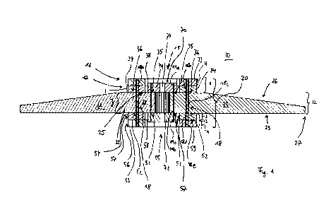
Fig. 1 shows a sectional view of a first embodiment of a foundation 10
according to the invention.
The foundation 10 is constructed, for example, in a pit (not shown) in the
ground (not shown),
possibly on a compacted clean layer (not shown). The foundation 10 according
to the invention
has a first vertically extending pedestal-like section 11 and a second
substantially horizontally
extending section 12. Furthermore, a third vertically downwardly extending
pedestal-like section
13 is provided under the second section 12, which is preferably provided in a
recess not shown.
The first section 11 has a pedestal-like design, which is made up of several
closed pedestal
sections 16, 17. If necessary, further pedestal sections can be provided.
The closed pedestal sections 16, 17 are made up of individual pedestal
segments 33, 34. The
pedestal sections 16, 17 are preferably designed here as circular rings, so
that the pedestal
section 11 has an interior 15. An alternative structure, e.g. a polygonal
structure, is possible.
The pedestal segments 33, 34 are provided butted next to each other so that
there are vertical
joints 38 between them. These are preferably designed as a gap, for example
with a thickness of
several millimeters, e.g. 30 mm. These vertical joints 38 are preferably not
filled with mortar or in-
situ concrete. Furthermore, preferably no horizontal connecting means are
provided.
Furthermore, the vertical joints of the individual pedestal sections 16, 17
are preferably provided
in such a way that the vertical joints 38 of adjacent pedestal sections 16, 17
are not aligned, i.e.
are not arranged one above the other. As shown in Fig. 2, it is advantageous
if the vertical joints
38 are always offset clockwise or counterclockwise by essentially the same
value. There are
horizontal joints 39 between the pedestal sections 16, 17, which are
preferably not filled with
mortar or in-situ concrete.
The second section 12 is flat. Alternatively, it can also be realized in a
star shape. Fig. 2 shows a
spatial view of the foundation 10. The second section 12 is made of horizontal
elements 22 in the
form of ribbed elements. These extend radially outwards as seen from the
interior 15.
They have a base plate 23 that is trapezoidal, for example, so that all of the
assembled base
plates form a polygonal surface that approximates a circular shape, whereby
spaces can be
provided between the individual base plates. Alternatively, circular segments
or a mixed form of
circular segment and trapezoidal shape are also possible.
At the inner end 24 of the base plate 23, a body 30 is provided with an upper
support section 25
with a lower support section 21 and side walls 29, which is preferably
substantially longer than
the width of the pedestal segments 33, 34 of the first section 11. Preferably,
the support sections
7
Date Recue/Date Received 2024-02-23
CA 03230233 2024-02-23
25, 21 have an inner upper section 35 pointing towards the inner spaces 15, 55
and an inner
lower section 51 as well as an outer upper section 36 and an outer lower
section 52 pointing
towards the outer end 27. Preferably, the pedestal sections 16, 17 are
arranged on the outer
section 35 and the pedestal sections 56, 57 are arranged under the outer
section 52.
A stiffening wall 26 is arranged at right angles to the base plate 23, the
height of which decreases,
for example, towards the outer end 27 of the base plate 23.
The body 30 has a transition area 32 with which the reinforcing wall 26 is
connected to the support
section 25 in a reinforcing manner.
Between the side surfaces 29 of the support sections 25, a distance is
preferably provided as a
vertical joint 40 when the horizontal elements 22 are arranged, which is
preferably designed as
an air gap. This results in vertical joints 40, which are also preferably not
filled with mortar or in-
situ concrete. Furthermore, preferably no horizontal connecting means are
provided.
An upwardly open cavity 28 is formed between two adjacent stiffening walls 26,
into which backfill
soil (not shown) can be introduced, whereby a ballast load can be applied to
the second section
12 of the foundation 10.
The third section 13 has a pedestal-like design, which is made up of several
closed pedestal
sections 56, 57. If necessary, further pedestal sections can be provided.
The closed pedestal sections 56, 57 are constructed from individual pedestal
segments 53, 54.
The pedestal sections 56, 57 are preferably designed here as circular rings,
so that an interior 55
is provided. An alternative structure, e.g. a polygonal structure, is
possible.
The pedestal segments 53, 54 are provided butted next to each other, so that
vertical joints 58
exist between them. These are preferably designed as a gap, for example with a
thickness of
several millimeters, e.g. 30 mm. These vertical joints 38 are preferably not
filled with mortar or in-
situ concrete. Furthermore, preferably no horizontal connecting means are
provided.
Furthermore, the vertical joints of the individual pedestal sections 56, 57
are preferably provided
in such a way that the vertical joints 58 of adjacent pedestal sections 56, 57
are not aligned, i.e.
are not arranged one above the other. As shown in Fig. 2, it is advantageous
if the vertical joints
58 are always arranged offset clockwise or counterclockwise by substantially
the same value.
There are horizontal joints 59 between the pedestal sections 56, 57, which are
preferably not filled
with mortar or in-situ concrete.
8
Date Recue/Date Received 2024-02-23
CA 03230233 2024-02-23
The foundation 10 has openings 18 that extend through the three sections 11,
12, 13. The
apertures 18 are made up of the aperture sections 18a to 18e. Tendons are
provided in these
apertures 18, with which the pedestal segments 33, 34, 53, 54 of sections 11,
13 and the body
30 of section 12 are braced together.
To form the apertures 18, the pedestal segments 33, 34 have vertical aperture
sections 18a, 18b
to form the apertures 18. Openings 18c are provided in the support section 25
and body 30 for
this purpose. The pedestal segments 53, 54 have vertical aperture sections
18d, 18e to form the
apertures 18.
To provide the necessary bracing between the pedestal sections 16, 17 of the
first section 11, the
horizontal elements 22 of the second section 12 and the pedestal sections 56,
57 of the third
section 13, an anchor cage (not shown) is preferably formed, which is formed
from an upper and
a lower abutment (not shown), which are connected to the tendons (not shown),
for example in
the form of anchor rods or reinforcement rods and counter elements (not
shown), for example
nuts. The upper abutment may also include a connection adapter (not shown) for
a tower (not
shown) of a wind turbine (not shown), for example if the tower is a steel
tower.
The upper pedestal sections 16, 17 form the pedestal segments 33, 34, the
lower pedestal
sections 56, 57 form the pedestal segments 53, 54 and the bodies 30 of the
horizontal element
22 of the section 12 form the pedestal 20 of the foundation 10.
The pedestal sections 17 and 57 have a height I, the pedestal sections 16 and
56 have a height
H and the bodies 30 have a height J.
The height H, I of the upper pedestal sections 16, 17 and the lower pedestal
sections 56, 57 is
designed in such a way that the pedestal sections 16, 17, 56, 57 are
essentially only loaded in
tension/compression when installed, i.e. they are loaded in the normal
direction. The
reinforcement is also designed for this (not shown), which essentially
consists of reinforcement in
the normal direction. Preferably, the height H and I are the same.
The height J of the bodies 30 is designed in such a way that they are
essentially only loaded in
shear when installed. The reinforcement is also designed for this (not shown),
which essentially
consists of reinforcement in the radial direction, particularly preferably in
the form of stirrups.
9
Date Recue/Date Received 2024-02-23
CA 03230233 2024-02-23
In order to increase the rigidity of the foundation 10, a clamping device 70
is provided, which is
connected to the second section 12. The clamping device 70 has at least one
clamping element
71, 72. Here, the clamping device 70 preferably has an upper clamping element
71 and a lower
clamping element 72, as in Figs. 1 to 4. Alternatively, only one of the two
clamping elements or
even more than two clamping elements 71, 72 may be provided, as shown for
example and by
way of example in Figs. 5, 6.
Preferably, a clamping element 71, 72 is designed as a continuous ring or as a
disk, possibly with
an opening 74. For example, a clamping element 71, 72 can also consist of
several individual
parts. This applies both to an annular design and to a disk-like design, as
shown in Figs. 1 to 4.
The clamping element 70 has at least one aperture 19. The upper clamping
element 71 has
aperture sections 19a and the lower clamping element 72 has aperture sections
19c.
Furthermore, breakthrough sections 19b are provided in the body 30 of the
horizontal element
22.
The upper clamping element 71 (if present) is arranged on the inner section 35
of the body 30 of
the horizontal element 22 so that the breakthrough sections 19a, 19b are
aligned. The lower
clamping element 72 (if present) is arranged under the inner section 51 of the
body 30 of the
horizontal element 22 so that the aperture sections 19b, 19c are aligned.
With the clamping elements 71, 72 mounted, the aperture sections 19a, 19b, 19c
form an aperture
19. The upper clamping element 71 is arranged in the interior 15 within the
pedestal sections 16,
17 of the first section 11. The lower clamping element 72 is arranged in the
interior 55 within the
pedestal sections 56, 57 of the third section 13.
In order to achieve a correspondingly effective increase in rigidity, it is
necessary to brace the
upper clamping element 71 and/or the lower clamping element 72 with the
horizontal element 22.
To provide the necessary bracing, tendons (not shown), for example in the form
of anchor rods
or reinforcement rods, are inserted into the apertures 19. These are then
tensioned and
prestressed with the upper clamping element 71, the lower clamping element 72
and/or the
horizontal element 22, for example via counter elements (not shown) such as
nuts. It is also
possible to design these as a type of anchor basket, as described above.
In the second embodiment of the foundation 10 according to the invention as
shown in Figs. 3, 4,
the upper clamping element 71 and/or the lower clamping element 72 each have a
projection 73,
which can be arranged continuously or intermittently around one side of the
clamping element 71,
Date Recue/Date Received 2024-02-23
CA 03230233 2024-02-23
72. This increases the rigidity of the foundation 10 in a simple manner and
improves the clamping
70.
The projection 73 preferably also serves as an assembly aid in connection with
the horizontal
elements 22. The projection 73 projects into the interior 15, 55. Preferably,
the outwardly facing
surface of the projection 73 is in contact with the inner surface of the body
30, which faces into
the interior 15, 55. Otherwise, the second embodiment is designed in the same
way as the first
embodiment.
Figs. 5, 6 show a third embodiment of the foundation 10 according to the
invention. In addition to
the clamping 70 of the first embodiment according to Figs. 1, 2 consisting of
the upper clamping
element 71 and/or the lower clamping element 72, the clamping 70 of the third
embodiment has
a further clamping element arrangement 75 between the pedestal sections 16, 17
or the pedestal
sections 56, 57 and the stiffening elements 71, 72. The further stiffening
element arrangement 75
preferably has at least one upper clamping ring 76 and/or one lower clamping
ring 77. Preferably,
the clamping rings 76, 77 are made in one piece or consist of at least two
clamping ring sections
78, 79 arranged one above the other. The clamping rings 76, 77 and/or the
clamping ring sections
78, 79 can be designed in one piece or as at least two clamping ring segments
80, 81.
The further clamping element arrangement 75 is arranged on a central section
37, 60 between
the outer section 36, 52 and the inner section 35, 51 of the upper and/or
lower support section
25, 21 of the body 30.
The clamping ring segments 80, 81 are provided butted next to each other so
that there are
vertical joints 82 between them. These are preferably designed as a gap, for
example with a
thickness of several millimeters, e.g. 30 mm. These vertical joints 82 are
preferably not filled with
mortar or in-situ concrete. Furthermore, preferably no horizontal connecting
means are provided.
Furthermore, the vertical joints 82 of the individual clamping ring sections
78, 79 are preferably
provided in such a way that the vertical joints 82 of adjacent clamping ring
sections 78, 79 are not
aligned, i.e. are not arranged one above the other. As shown in Fig. 6, it is
advantageous if the
vertical joints 82 are always arranged offset clockwise or counterclockwise by
substantially the
same value. There are horizontal joints 83 between the clamping ring sections
78, 79, which are
preferably not filled with mortar or in-situ concrete. In addition, the upper
clamping element 71
and/or the lower clamping element 72 can each have a projection 73
corresponding to the second
embodiment. Otherwise, the third embodiment is designed like the first
embodiment.
11
Date Recue/Date Received 2024-02-23
CA 03230233 2024-02-23
The clamping element arrangement 75 has at least one aperture 84. The clamping
ring sections
78, 79 have aperture sections 84a, 84b. Furthermore, aperture sections 84c are
provided in the
body 30 of the horizontal element 22.
The clamping ring portions 78, 79 (if present) are arranged on and/or under
the central portion
37, 60 of the body 30 of the horizontal member 22 such that the aperture
portions 84a, 84b, 84c.
With the clamping ring sections 78, 79 fitted, the aperture sections 84a, 84b,
84c form the aperture
84.
In order to achieve a correspondingly effective increase in rigidity, it is
necessary to brace at least
one of the clamping ring sections 78, 79 with the horizontal element 22. To
provide the necessary
bracing, tendons (not shown), for example in the form of anchor rods or
reinforcement rods, are
inserted into the apertures 84. These are then tensioned and prestressed with
the upper clamping
ring 76, the lower clamping ring 77 and/or the horizontal element 22, for
example via counter
elements (not shown) such as nuts. It is also possible to design these as a
type of anchor cage,
as described above.
The clamping ring sections 78 have a height K, the clamping ring sections 79
have a height L and
the bodies 30 have a height J.
The height K and the height L of the clamping ring sections 78, 79 are
designed in such a way
that the clamping ring sections 78, 79 are essentially only subjected to
tension/compression when
installed, i.e. they are loaded in the normal direction. The reinforcement is
also designed for this
(not shown), which essentially consists of reinforcement in the normal
direction. Preferably, the
heights K and L are the same.
The height J of the bodies 30 is designed in such a way that they are
essentially only loaded in
shear when installed. The reinforcement is also designed for this (not shown),
which essentially
consists of reinforcement in the radial direction, particularly preferably in
the form of stirrups.
12
Date Recue/Date Received 2024-02-23