Note: Descriptions are shown in the official language in which they were submitted.
WO 2023/034635
PCT/US2022/042629
FILED SEPTEMBER 6, 2022 Docket P27611PC01 (508835-
US-2)
Auto-Engageable Coupling for Preventing
Transmission of Reverse Rotation to ESP Motors
Related Applications
[001] This application claims the benefit of United States Provisional Patent
Application
Serial No. 63/240,755 filed September 3, 2021, entitled "Auto-Engageable
Coupling
for Preventing Transmission of Reverse Rotation to ESP Motors," the disclosure
of
which is incorporated by reference as if fully set forth herein.
Field of the Invention
[002] The subject matter disclosed herein relates to electric motors, and more
specifically to
electric motors for use in connection with electric submersible pumps (ESPs)
in oil and
gas applications.
Background
[003] Oil is typically produced by drilling wells into oil reservoirs in
geological formations
and then pumping the oil out of the reservoirs through the wells. Commonly,
the oil is
produced using ESPs that are deployed in the wells. Electric power suitable
for the
respective ESPs is normally generated by electric drive systems that are
positioned at
the surface of each well, and is conveyed from the drive to the ESP via a
power cable
that extends from the drive system to the deployed ESP.
[004] An ESP typically includes a pump section, a seal section, and a motor
section. The
power from the electric drive system is provided to the motor, which drives
the pump
section. Frequently, the motor is a rotary motor which drives a shaft that is
coupled to
the shaft of a centrifugal pump. The rotating motor shaft causes the pump
shaft to rotate,
generating fluid pressure that forces fluid out of the well.
1
CA 03230462 2024- 2- 28
WO 2023/034635
PCT/US2022/042629
[005] The motor is typically one of two types: an induction motor; or a
permanent magnet
motor. In the case of an induction motor, power (usually three-phase AC power)
is
provided to the windings of the motor's stator, causing the stator to generate
rotating
magnetic fields in the stator. These rotating magnetic fields induce currents
and
corresponding magnetic fields in a rotor, causing the rotor and the motor
shaft to rotate
and drive the pump. In the case of a permanent magnet motor, three-phase AC
power
is provided to the motor's stator windings, generating rotating magnetic
fields as in the
induction motor. The rotor of the permanent magnet motor, however, has a set
of
permanent magnets which cause the rotor to rotate in the rotating magnetic
fields
generated by the stator. $
[006] As explained above, in normal operation, power supplied to a
conventional permanent
magnet ESP motor causes the motor to rotate, which causes fluid (e.g., oil) to
flow
through the pump. What is less frequently considered, however, is that the
reverse of
this sequence may also be true. In other words, the motor can act as a
generator. If fluid
is caused to flow through the pump, this may cause the pump to rotate, which
will in
turn cause the motor to rotate and generate an AC voltage which is applied to
the
conductors of the power cable. The generated voltage is often unexpected since
the
motor normally consumes electrical energy, and it may be dangerous or even
fatal to
persons working on the system. It would therefore be desirable to provide
means to
protect these people from the electric potential that may be generated by an
ESP motor
acting as a generator.
Summary of the Invention
[007] Certain embodiments commensurate in scope with the original claims are
summarized
below. These embodiments are not intended to limit the scope of the claims,
but rather
these embodiments are intended only to provide a brief summary of possible
forms of
2
CA 03230462 2024- 2- 28
WO 2023/034635
PCT/US2022/042629
the claimed subject matter. Indeed, the claims may encompass a variety of
forms that
may be similar to or different from the embodiments set forth below.
[008] In one embodiment, the present disclosure is directed to an auto-
engageable coupling
for use in a pumping system that includes an electric motor, a pump driven by
the
electric motor and a seal section disposed between the pump and the motor. The
auto-
engageable coupling permits the transfer of torque from the motor to the pump,
but
prevents the pump from applying torque to the motor.
[009] In some embodiments, the auto-engageable coupling includes a drive plate
connected
to a motor shaft and a reaction plate connected to a seal section shaft. The
drive plate
and reaction plate are only coupled together to transmit torque from the motor
to the
pump when the motor is activated and rotating in a first direction. When the
motor is
not activated and the pump is forced to rotate in a second direction, the
drive plate and
the reaction plate are disengaged to prevent the delivery of torque from the
pump to the
motor.
[010] In an embodiment, the auto-engageable coupling includes a drive plate
connected to a
motor shaft driven by the motor and a reaction plate connected to an output
shaft The
drive plate and reaction plate permit the transmission of torque from the
motor to the
pump when the motor is energized for rotation in an intended direction, but
prevent the
transmission of torque from the pump to the motor when the motor is not
energized for
rotation. In this embodiment, the auto-engageable coupling also includes a
braking
mechanism that is configured to resist the rotation of the output shaft in an
unintended
direction.
[011] In another embodiment, the present disclosure is directed to an auto-
engageable
coupling for use in connection with a submersible pumping system that includes
a pump
and a motor. In this embodiment, the auto-engageable coupling include a drive
cup
3
CA 03230462 2024- 2- 28
WO 2023/034635
PCT/US2022/042629
connected to a motor shaft driven by the motor, an output cup connected to an
output
shaft, and a drive bearing clutch connected between the drive cup and the
output cup.
The drive bearing clutch is configured to lock the drive cup and the output
cup together
when the motor shaft is driven in an intended direction. The auto-engageable
coupling
further includes a brake bearing clutch configured to resist the rotation of
the output
shaft in an unintended direction.
[012] In yet another embodiment, the present disclosure is directed to a
submersible pumping
system that has a motor, a motor shaft that transfers torque from the motor,
and a pump
driven by the motor. The pump is connected directly or indirectly to an output
shaft.
The pumping system also includes an auto-engageable coupling connected between
the
motor shaft and the output shaft. The auto-engageable coupling has a drive
plate
connected to the motor shaft and a reaction plate connected to the output
shaft. The
drive plate and reaction plate permit the transmission of torque from the
motor to the
pump when the motor is energized for rotation in an intended direction.
Brief Descriptions of the Drawings
[013] These and other features, aspects, and advantages of the present
disclosure will become
better understood when the following detailed description is read with
reference to the
accompanying drawings in which like characters represent like parts throughout
the
drawings, wherein:
[014] FIG. 1 presents an overview of a submersible pumping system deployed in
well.
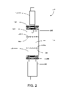
[015] FIG. 2 presents a side view of an auto-engageable coupling constructed
in accordance
with a first embodiment
[016] FIG. 3 presents a perspective view of the auto-engageable coupling of
FIG. 2 installed
within the seal section base and motor head.
[017] FIG. 4 presents a cross-sectional view of the auto-engageable coupling
of FIG. 3.
4
CA 03230462 2024- 2- 28
WO 2023/034635
PCT/US2022/042629
[018] FIG. 5 presents a perspective view of the torque-engagement mechanism in
the drive
plate of the auto-engageable coupling of FIG. 2.
[019] FIG. 6 presents a side view of an auto-engageable coupling constructed
in accordance
with a first embodiment in a state of normal operation in which the motor
drives the
pump in a first (clockwise) direction.
[020] FIG. 7 presents a side view of the auto-engageable coupling of FIG. 2 in
a state in which
the motor rotates in a second (counterclockwise) direction when energized.
110211 FIG. 8 presents a side view of the auto-engageable coupling of FIG. 2
in a state in which
the auto-engageable coupling isolates the motor from an unintentional
clockwise
rotation induced in the pump.
[022] FIG. 9 presents a side view of the auto-engageable coupling of FIG. 2 in
a state in which
the auto-engageable coupling arrests the counterclockwise rotation of the pump
while
isolating the motor from the counterclockwise rotation.
[023] FIG. 10 presents cross-sectional view of an auto-engageable coupling
constructed in
accordance with a second embodiment.
[024] FIG. 11 presents a perspective view of a one-way roller clutch from the
auto-engageable
coupling of FIG. 10.
[025] FIG. 12 presents a side view of an auto-engageable coupling constructed
in accordance
with a third embodiment.
[026] FIGS. 13A presents a cross-sectional view of an auto-engageable coupling
constructed
in accordance with a fourth embodiment in an engaged position.
[027] FIGS. 13B presents a cross-sectional view of an auto-engageable coupling
constructed
in accordance with a fourth embodiment in a disengaged position.
[028] FIG. 14 presents a side view of an auto-engageable coupling constructed
in accordance
with a fifth embodiment.
CA 03230462 2024- 2- 28
WO 2023/034635
PCT/US2022/042629
[029] FIG. 15 presents a cross-sectional view of the auto-engageable coupling
of FIG. 14.
[030] FIG. 16 presents a plan view of the sprag clutch assembly of the auto-
engageable
coupling of FIG. 15.
Detailed Description
[031] One or more specific embodiments will be described below. In an effort
to provide a
concise description of these embodiments, all features of an actual
implementation may
not be described in the specification. It should be appreciated that in the
development
of any such actual implementation, as in any engineering or design project,
numerous
implementation-specific decisions must be made to achieve the developers'
specific
goals, such as compliance with system-related and business-related
constraints, which
may vary from one implementation to another. Moreover, it should be
appreciated that
such a development effort might be complex and time consuming, but would
nevertheless be a routine undertaking of design, fabrication, and manufacture
for those
of ordinary skill having the benefit of this disclosure.
[032] When introducing elements of various embodiments of the present
disclosure, the
articles "a," "an," "the," and "said" are intended to mean that there are one
or more of
the elements. The terms "comprising," "including," and "having" are intended
to be
inclusive and mean that there may be additional elements other than the listed
elements.
Furthermore, any numerical examples in the following discussion are intended
to be
non-limiting, and thus additional numerical values, ranges, and percentages
are within
the scope of the disclosed embodiments.
[033] In accordance with an embodiment of the present invention, FIG. 1 shows
an
elevational view of a pumping system 100 attached to production tubing 102.
The
pumping system 100 and production tubing 102 are disposed in a wellbore 104,
which
is drilled for the production of a fluid such as water or petroleum. As used
herein, the
6
CA 03230462 2024- 2- 28
WO 2023/034635
PCT/US2022/042629
term "petroleum" refers broadly to all mineral hydrocarbons, such as crude
oil, gas and
combinations of oil and gas. The production tubing 102 connects the pumping
system
100 to a wellhead 106 located on the surface. Although the pumping system 100
is
primarily designed to pump petroleum products, it will be understood that the
present
invention can also be used to move other fluids. It will also be understood
that, although
each of the components of the pumping system are primarily disclosed in a
submersible
application, some or all of these components can also be used in surface
pumping
operations.
[034] The pumping system 100 includes some combination of a pump 108, a motor
110 and
a seal section 112. The motor 110 is an electrical motor that receives power
from a
surface-mounted motor control unit (not shown). In exemplary embodiments, the
motor 110 is a permanent magnet motor. When energized, the motor 110 drives a
shaft
that causes the pump 108 to operate. The seal section 112 shields the motor
110 from
mechanical thrust produced by the pump 108 and provides for the expansion of
motor
lubricants during operation. The seal section 112 also isolates the motor 110
from the
wellbore fluids. The seal section 112 includes a housing (not separately
designated)
configured to protect the internal components of the seal section 112 from the
exterior
wellbore environment. It may be desirable to use tandem-motor combinations,
multiple
seal sections, multiple pump assemblies or other downhole components not shown
in
FIG. 1.
[035] The pumping system 100 includes an auto-engageable coupling 114 between
the motor
110 and the seal section 112. Generally, the auto-engageable coupling 114
facilitates
the intended transmission of torque from the motor 110 to the seal section 112
and
pump 108, while preventing the unintentional transmission of torque from the
pump
108 to the motor 110. This mitigates the risk of creating a fugitive back-EMF
force by
7
CA 03230462 2024- 2- 28
WO 2023/034635
PCT/US2022/042629
turning the motor 110 with torque generated by fluid falling or otherwise
passing
through the pump 108. The auto-engageable coupling 114 also prevents the
transmission of torque from the motor 110 to the pump 108 if the motor 110
rotates in
the wrong direction when energized.
[036] Turning to FIG. 2, shown therein is an isolated depiction of the auto-
engageable
coupling 114 constructed in accordance with a first embodiment. It will be
appreciated
that the auto-engageable coupling 114 is configured to reside inside the
pumping
system 100 along the driveline between the motor 110 and pump 108. For
example,
as indicated in FIGS. 3 and 4, a portion of the auto-engageable coupling 114
resides in
a head 116 of the motor 110 ("motor head 116-) and within a base 118 of the
seal
section 112 ("seal section base 118").
[037] In the first embodiment, the auto-engageable coupling 114 includes a
cylindrical drive
plate 120, a cylindrical reaction plate 122, and a cylindrical braking plate
124. The
drive plate 120 is connected to a motor shaft 126 (or "input shaft-) that is
in turn
connected to the rotor of the motor 110. The drive plate 120 is configured to
rotate
with the motor shaft 126. The reaction plate 122 is connected to, and
configured for
rotation with, an output shaft 128. In some embodiments, the output shaft 128
is a seal
section shaft extending through the seal section 112. In other embodiments,
the output
shaft 128 is a pump shaft that extends into the pump 108. In each case, the
output shaft
128 is connected directly or indirectly to the rotational components (e.g.,
impellers or
rotors) of the pump 108.
[038] The drive plate 120 includes drive plate teeth 132 that are configured
to engage with
reaction plate lower teeth 134 under certain conditions, while allowing the
drive plate
120 and reaction plate 122 to rotate with respect to one another under
different
conditions. Similarly, the braking plate 124 includes braking plate teeth 136
that are
8
CA 03230462 2024- 2- 28
WO 2023/034635
PCT/US2022/042629
configured to engage with reaction plate upper teeth 138 under certain
conditions, while
allowing the braking plate 124 and reaction plate 122 to rotate with respect
to one
another under different conditions.
[039] In the present embodiment, the drive plate teeth 132, reaction plate
lower teeth 134,
braking plate teeth 136, and reaction plate upper teeth 138 are configured as
asymmetrical, unidirectional teeth. The drive plate teeth 132 and reaction
plate lower
teeth 134 are each configured to mesh and engage one another in a locked
manner when
the drive plate 120 is rotated under torque from the motor 110 in a first
direction (e.g.,
clockwise). When the drive plate 120 is rotated in a second direction (e.g.,
counterclockwise), the shape of the drive plate teeth 132 and reaction plate
lower teeth
134 allows movement between the drive plate 120 and the reaction plate 122.
Similarly,
when the reaction plate 122 is driven in a second direction (e.g.,
counterclockwise), the
reaction plate upper teeth 138 engage and mesh with the braking plate teeth
136. If the
reaction plate 122 is rotated in the first direction (e.g., clockwise), the
reaction plate
upper teeth 138 do not engage with the braking plate teeth 136, thereby
allowing the
reaction plate 122 to rotate with respect to the stationary braking plate 124.
[040] The output shaft 128 passes through the braking plate 124. The braking
plate 124 is
prevented from rotation by guide pins 140, which extend from inside the seal
section
base 118. The guide pins 140 are captured within vertical guide slots 142 in
the braking
plate 124, which allows the braking plate 124 to be axially displaced within
the seal
section base 118.
[041] The drive plate 120 and braking plate 124 are each configured for axial
displacement
relative to the reaction plate 122. The auto-engageable coupling 114 includes
a lower
spring 144 that forces the drive plate 120 towards the reaction plate 122. An
upper
spring 146 above the braking plate 124 forces the braking plate 124 towards
the reaction
9
CA 03230462 2024- 2- 28
WO 2023/034635
PCT/US2022/042629
plate 122. Additionally, the drive plate 120 includes a torque displacement
mechanism
148 that includes a spiraled gear 150 on the end of the motor shaft 126 that
engages
with interior slots 152 within the drive plate 120. When the drive plate 120
is rotated
in the first direction by the motor shaft 126 under torque from engagement
with the
reaction plate 122, the drive plate 120 is pushed against the reaction plate
122 by the
torque displacement mechanism 148. If the drive plate 120 is not transmitting
torque
to the reaction plate 122, the drive plate 120 is not axially displaced by the
torque
displacement mechanism 148.
[042] In exemplary embodiments, the drive plate 120 only fully engages the
reaction plate
122 in a normal drive mode when the lower spring 144 and the torque
displacement
mechanism 148 cooperatively push the drive plate 120 into full engagement with
the
reaction plate 122. If the torque displacement mechanism 148 is not activated
by the
realization of torque between the drive plate 120 and the reaction plate 122,
the force
provided by the lower spring 144 is insufficient to fully engage the drive
plate 120 and
the reaction plate 122, thereby allowing the reaction plate 122 and drive
plate 120 to
rotate with respect to one another without the transmission of torque from the
motor
shaft 126 to the output shaft 128.
[043] Similarly, the upper spring 146 is configured to press the non-rotating
braking plate 124
into an approximated position with respect to the reaction plate 122. If the
reaction
plate 122 rotates in the second (e.g., counterclockwise) direction, the
braking plate teeth
136 will engage the reaction plate upper teeth 138 and prevent the reaction
plate 122
from rotating. If, on the other hand, the reaction plate 122 is rotating in
the first
direction (e.g., clockwise), the reaction plate upper teeth 138 will pass
under the braking
plate teeth 136 with minimal or no contact. It will be appreciated that the
motor shaft
CA 03230462 2024- 2- 28
WO 2023/034635
PCT/US2022/042629
126 and output shaft 128 are both held in a fixed axial position by thrust
bearings or
other containment mechanisms.
[044] Turning to FIG. 6, shown therein is a depiction of the auto-engageable
coupling 114 in
a first state, which can be characterized as a normal drive mode of operation.
The motor
110 is driving the motor shaft 126 in the first direction (e.g., clockwise
looking at the
motor 110 from the pump 108) and the lower spring 144 and torque displacement
mechanism 148 have pushed the drive plate 120 into full engagement with the
reaction
plate 122. The drive plate 120 and reaction plate 122 are engaged to transmit
torque
between the motor shaft 126 and the output shaft 128. The clockwise rotation
of the
reaction plate 122 permits the reaction plate 122 to rotate under the
stationary braking
plate 124 without engagement between the reaction plate upper teeth 138 and
the
braking plate teeth 136.
[045] Turning to FIG. 7, shown therein is a depiction of the auto-engageable
coupling 114 in
a second state. In this second state, the motor 110 has been energized, but is
rotating
in an unintended second (e.g., counterclockwise) direction. Because the
rotation of the
drive plate 120 in a counterclockwise direction prohibits engagement with the
reaction
plate 122, the torque displacement mechanism 148 is not activated to fully
deploy the
drive plate 120 against the reaction plate 122. In this second mode of
operation, the
drive plate 120 rotates under the reaction plate 122 which is locked into a
stationary
position through engagement with the braking plate 124.
[046] Turning to FIG. 8, shown therein is a depiction of the auto-engageable
coupling 114 in
a third state. In this third state of operation, the pump 108 is rotating in
the first direction
(e.g., clockwise), but the motor 110 has not been activated to transmit torque
to the
pump 108. The pump 108 could be forced into rotation in the clockwise
direction while
the pump 108 is being run into the wellbore 104, or from the passage of
pressurized
11
CA 03230462 2024- 2- 28
WO 2023/034635
PCT/US2022/042629
well fluids through the pump 108 into the production tubing 102 (e.g., during
a "well
kick"). In this mode of operation, the reaction plate 122 rotates in the
clockwise
direction without engaging the drive plate 120 or the braking plate 124. In
this way,
the auto-engageable coupling 114 isolates the torque generated by the passive
rotation
of the pump 108 from being transmitted to the motor 110. This prevents the
motor 110
from generating a back EMF force from the torque produced by the pump 108.
[047] Turning to FIG. 9, shown therein is a depiction of the auto-engageable
coupling 114 in
a fourth state. In this fourth state of operation, the pump 108 is being
driven in the
reverse direction (e.g., counterclockwise) by fluid falling through the
production tubing
102. This could be caused by an injection operation in which fluid is injected
into the
production tubing through the wellhead when power is lost or removed from the
motor
110, or while pulling the pump 108 out of the wellbore 104. The output shaft
128 drives
the reaction plate 122 in the counterclockwise direction, which forces the
reaction plate
122 into a locked relationship with the braking plate 124. The braking plate
124
prevents the reaction plate 122 (and drive plate 120) from rotating in the
counterclockwise, reverse direction.
[048] Turning to FIG. 10, shown therein is a second embodiment of the auto-
engageable
coupling 114. In the embodiment depicted in FIG. 10, the braking plate 124 has
been
replaced by a braking clutch bearing 154. The braking clutch bearing 154
(depicted in
FIG. 11) permits the output shaft 128 to rotate in the intended clockwise
direction, but
applies a braking force to the output shaft 128 when it is rotated in the
counterclockwise
direction. The one-way braking clutch bearing 154 includes a plurality of
captured
individual roller bearings (not separately designated) that roll freely in
response to the
rotation of the output shaft 128 in one direction, but resist rolling when the
output shaft
128 is rotated within the braking clutch bearing 154 in the opposite
direction.
12
CA 03230462 2024- 2- 28
WO 2023/034635
PCT/US2022/042629
[049] Turning to FIG. 12, shown therein is a third embodiment of the auto-
engageable
coupling 114. In this third embodiment, the auto-engageable coupling 114
includes a
drive cup 156 connected to the motor shaft 126 and an output cup 158 connected
to the
output shaft 128. The auto-engageable coupling 114 includes a one-way drive
bearing
clutch 160 between the drive cup 156 and output cup 158. The one-way drive
bearing
clutch 160 allows rotation between an interior and an exterior component when
the
interior component is rotated in a first direction, but locks the interior
component and
exterior component together when rotated in a second, opposite direction. The
drive
bearing clutch 160 is configured so that intentional rotation of the motor
shaft 126 (e.g.,
in the clockwise direction) is transferred to the output shaft 128 through
locking the
drive bearing clutch 160, while permitting the rotation of the output shaft
128 in the
intended direction. However, when the motor shaft 126 rotates in an unintended
direction (e.g., in the counterclockwise direction), the drive bearing clutch
160 is not
locked and torque is not transmitted from the motor shaft 126 to the output
shaft 128.
[050] In this embodiment, the brake bearing clutch 162 is configured to
discourage the
rotation of the output shaft 128 in a counterclockwise direction. Accordingly,
if the
pump 108 induces a counterclockwise rotation in the output shaft 128, the
brake bearing
clutch 162 locks the output shaft 128 against the braking plate 124 or other
stationary
component within the auto-engageable coupling 114.
[051] Turning to FIGS. 13A and 13B, shown therein is a fourth embodiment of
the auto-
engageable coupling 114. In the embodiment depicted in FIGS. 13A and 13B, the
auto-
engageable coupling 114 includes a central coupling 164 that includes input
splines 166
for receiving the motor shaft 126 and output splines 168 for receiving the
output shaft
128. A drive spring 170 located on the motor shaft 126 is configured to apply
an upward
force against the central coupling 164. The central coupling 164 further
includes helical
13
CA 03230462 2024- 2- 28
WO 2023/034635
PCT/US2022/042629
grooves 172 that are configured to accept a shaft pin 174 at the end of the
output shaft
128.
[052] During normal operation, the central coupling 164 remains in the
deployed ("engaged")
position in which the output shaft 128 is engaged with the output splines 168
of the
central coupling 164, as depicted in FIG. 13A. If, however, the output shaft
128 is
forced into rotation in a reverse direction, the engagement between the shaft
pin 174
and the helical grooves 172 forces the central coupling 16 into a retracted
position
("disengaged") against the compressive force applied by the drive spring 170,
as
depicted in FIG. 13B.
[053] Turning to FIGS. 14-16, shown therein are depictions of a fifth
embodiment of the auto-
engageable coupling 114 in which the braking plate 124 or one-way clutch
bearing 154
has been replaced by a sprag bearing assembly 176. The sprag bearing assembly
176
includes a sprag bearing cage 178 that is contained within the housing 184 of
the auto-
engageable coupling 114, which can be integrated within the motor 110, pump
108 or
seal section 112, or presented as a standalone component within the pumping
system
100. The sprag bearing cage 178 includes a plurality of directionally oriented
tooth-
like sprag members 180 (depicted in FIG. 16). The sprag bearing assembly 176
further
includes a runner 182 that is connected for rotation with the output shaft
128.
[054] In this embodiment, the motor shaft 126 is connected to the drive plate
120, which
engages with the reaction plate 122 as previously disclosed. The output shaft
128 is
connected to the runner 182, which rotates with the output shaft 128 within
the sprag
bearing assembly 176 when the output shaft 128 is rotated in the intended,
motor-driven
direction. If the output shaft 128 is caused to rotate in the unintended
direction, either
by the pump 108 or the motor 110, the rotation of the runner 182 is resisted
by the sprag
bearing assembly 176.
14
CA 03230462 2024- 2- 28
WO 2023/034635
PCT/US2022/042629
[055] Thus, in each embodiment, the auto-engageable coupling 114 includes a
drive plate 120
coupled to the motor shaft 126 and a reaction plate 122 coupled to the output
shaft 128,
which is selectively coupled to the motor shaft 126 when the motor shaft 126
is rotated
in the intended direction. When the motor shaft 126 is rotated in an
unintended
direction, the reaction plate 122 and drive plate 120 do not engage and torque
is not
transferred to the output shaft 128. The output shaft 128 is also coupled to a
directional
braking mechanism, which resists the rotation of the output shaft 128 in an
unintended
direction. As used herein, the term "braking mechanism" includes, but is not
limited
to, to the braking plate 124, the one-way clutch bearing 154, the brake
bearing clutch
162, or the sprag clutch assembly 176. In each embodiment, the auto-engageable
coupling 114 can be filled with liquid lubricants to ensure the long-lasting
performance
of the auto-engageable coupling 114.
[056] This written description uses examples to disclose the claimed subject
matter, including
the best mode, and also to enable any person skilled in the art to practice
the subject
matter, including making and using any devices or systems and performing any
incorporated methods. The patentable scope of the disclosure is defined by the
claims,
and may include other examples that occur to those skilled in the art. Such
other
examples are intended to be within the scope of the claims if they have
structural
elements that do not differ from the literal language of the claims, or if
they include
equivalent structural elements with insubstantial differences from the literal
languages
of the claims.
CA 03230462 2024- 2- 28