Note: Descriptions are shown in the official language in which they were submitted.
DEMANDE OU BREVET VOLUMINEUX
LA PRESENTE PARTIE DE CETTE DEMANDE OU CE BREVET COMPREND
PLUS D'UN TOME.
CECI EST LE TOME 1 DE 2
CONTENANT LES PAGES 1 A 209
NOTE : Pour les tomes additionels, veuillez contacter le Bureau canadien des
brevets
JUMBO APPLICATIONS/PATENTS
THIS SECTION OF THE APPLICATION/PATENT CONTAINS MORE THAN ONE
VOLUME
THIS IS VOLUME 1 OF 2
CONTAINING PAGES 1 TO 209
NOTE: For additional volumes, please contact the Canadian Patent Office
NOM DU FICHIER / FILE NAME:
NOTE POUR LE TOME / VOLUME NOTE:
CA 03230660 2024-02-28
WO 2023/031032 PCT/EP2022/073763
1
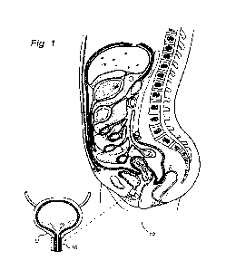
APPARATUS AND METHOD FOR OBTAINING URINARY CONTROL
Technical field
[0001] The
present invention relates to an implantable apparatus for obtaining urinary
control and
emptying of the urinary bladder, thereby preventing or treating involuntary
urinary retention. More
particularly, the invention relates to an implantable apparatus for
discharging urine from the urinary
bladder with a powered member operating from the outside of the urinary
bladder assisted by a support
structure.
Background
[0002] Urinary dysfunction is commonly caused by spinal cord injuries which
involve involuntary
urinary retention. This condition is associated with urinary infections, renal
damages, or damages to the
urinary tract. A common treatment of urinary retention is continuous or
intermittent catherization.
Besides the inconvenience for the patient, catheters always represent a risk
of acquiring infections.
Summary
[0003] According to an aspect, an implantable pumping device for evacuating
urine from the urinary
bladder of a patient is provided. The implantable pumping device comprises a
first constriction device
configured to constrict a portion of the urinary bladder for closing a first
portion of the urinary bladder.
The implantable pumping device further comprises a second constriction device
configured to constrict
a second portion of the urinary bladder, downstream the first portion, for
evacuating urine from the
urinary bladder when the first portion of the urinary bladder is closed. The
implantable pumping device
further comprises a controller configured to control the first and second
constriction device.
[0004] According to an aspect, an implantable pumping device for evacuating
urine from the urinary
bladder (U) of a patient is provided. The implantable pumping device comprises
a rotor carrying a
constriction device. The constriction device comprises a first constriction
element, a second
constriction element and a third constriction element. The constriction
elements are position
equidistantly from an axis of rotation of the rotor. The implantable pumping
device further comprises a
support element spaced from the rotor. The implantable pumping device is
applied on the urinary
bladder so that the urinary bladder extends between the support element and
the rotor. The implantable
pumping device further comprises a controller configured to control the rotor
so that the constriction
elements successively constrict a series of selected portions of the urinary
bladder in order to evacuate
urine from the urinary bladder.
[0005]
According to an aspect, an implantable pumping device for evacuating urine
from the
urinary bladder of a patient is provided. The implantable pumping device
comprises a first operably
hydraulic constriction element configured to be inflated to constrict the
urinary bladder for restricting
the flow of fluid the rethrough. The implantable pumping device further
comprises a second operable
hydraulic constriction element configured to be inflated to constrict the
urinary bladder for restricting
the flow of fluid the rethrough and for evacuating urine from the urinary
bladder. The implantable
pumping device further comprises an interconnecting fluid conduit fluidly
connecting the first operable
hydraulic constriction element to the second operable hydraulic constriction
element. The first operable
RECTIFIED SHEET (RULE 91) ISA/EP
CA 03230660 2024-02-28
WO 2023/031032 PCT/EP2022/073763
2
hydraulic constriction element is configured to be placed at a first portion
of the urinary bladder for
constricting the first portion of the luminary organ for restricting the flow
of fluid therethrough, the
second operable hydraulic constriction element is configured to be placed at a
second portion of the
urinary bladder, downstream the first portion, for constricting the second
portion of the urinary bladder
for restricting the flow of fluid therethrough and for evacuating urine from
the urinary bladder, and the
interconnecting fluid conduit is configured to conduct fluid from the first
operable hydraulic
constriction element to the second operable hydraulic constriction element
when the pressure increases
in the first operable hydraulic constriction element, such that second
operable hydraulic constriction
element constricts the second portion of the urinary bladder further.
[0006] According to an aspect, an implantable pumping device for evacuating
urine from a urinary
bladder of a patient is provided. The implantable pumping device comprises a
first implantable
constriction device for constricting the urinary bladder. The first
implantable constriction device
comprises a first operable hydraulic constriction element configured to be
inflated and thereby expand
in a first direction towards the urinary bladder to constrict a first portion
of the urinary bladder for
restricting the flow of fluid therethrough. The first implantable constriction
device further comprises a
supporting operable hydraulic constriction element configured to be inflated
and thereby expand in the
first direction towards the urinary bladder to support the first operable
hydraulic constriction element in
constricting the first portion of the urinary bladder for restricting the flow
of fluid therethrough. The
implantable pumping device further comprises a second implantable constriction
device similar to the
first implantable constriction device. The second implantable constriction
device is configured to
constrict a second portion of the urinary bladder downstream the first portion
in order to evacuate urine
from the urinary bladder. The second portion extends a longer distance along
an axial direction than the
first portion.
[0007] According to an aspect, an implantable pumping device for evacuating
urine from a urinary
bladder of a patient is provided. The implantable pumping device comprises a
first constriction device
for constricting the urinary bladder. The first constriction device comprises
a first operable hydraulic
constriction element configured to be inflated to exert a pressure on the
urinary bladder in a first
direction to constrict a first portion of the urinary bladder for restricting
the flow of fluid therethrough.
The first constriction device further comprises a second operable hydraulic
constriction element
configured to be inflated to exert a pressure on the urinary bladder in a
second direction to constrict the
first portion of the urinary bladder for restricting the flow of fluid
therethrough. The first constriction
device further comprises a first hydraulic system in fluid connection with the
first operable hydraulic
constriction element. The first constriction device further comprises a second
hydraulic system in fluid
connection with the second operable hydraulic constriction element. The first
and second operable
hydraulic constriction elements are adjustable independently from each other.
The implantable
pumping device further comprises a second constriction device for constricting
the urinary bladder and
for evacuating urine from the urinary bladder. The second constriction device
comprises a third
operable hydraulic constriction element configured to be inflated to exert a
pressure on the urinary
bladder in a first direction to constrict a second portion of the urinary
bladder for restricting the flow of
RECTIFIED SHEET (RULE 91) ISA/EP
CA 03230660 2024-02-28
WO 2023/031032 PCT/EP2022/073763
3
fluid therethrough and for evacuating urine from the urinary bladder. The
second constriction device
further comprises a fourth operable hydraulic constriction element configured
to be inflated to exert a
pressure on the urinary bladder in a second direction to constrict the second
portion of the urinary
bladder for restricting the flow of fluid therethrough and for evacuating
urine from the urinary bladder.
The second constriction device further comprises a third hydraulic system in
fluid connection with the
third operable hydraulic constriction element. The second constriction device
further comprises a fourth
hydraulic system in fluid connection with the fourth operable hydraulic
constriction element. The third
and fourth operable hydraulic constriction elements are adjustable
independently from each other.
[0008] According to an aspect, an implantable pumping device for evacuating
urine from the
urinary bladder of a patient is provided. The implantable pumping device
comprises a first constriction
device for constricting the urinary bladder. The first constriction device
comprises an operable
hydraulic constriction element configured to be inflated to exert a pressure
on the urinary bladder. The
first constriction device further comprises a first hydraulic reservoir for
holding a hydraulic fluid. The
first constriction device further comprises a first hydraulic pump for pumping
fluid from the first
hydraulic reservoir to the first operable hydraulic constriction element. The
first constriction device
further comprises a first fluid conduit creating a fluid connection between
the first hydraulic
reservoir and the first hydraulic pump. The implantable pumping device further
comprises a second
constriction device for constricting the urinary bladder downstream the first
constriction device for
evacuating urine from the urinary bladder. The second constriction device
comprises a second operable
hydraulic constriction element configured to be inflated to exert a pressure
on the urinary bladder. The
second constriction device further comprises a second hydraulic reservoir for
holding a hydraulic fluid.
The second constriction device further comprises a second hydraulic pump for
pumping fluid from the
second hydraulic reservoir to the second operable hydraulic constriction
element. The second
constriction device further comprises a second fluid conduit creating a fluid
connection between the
second hydraulic reservoir and the second hydraulic pump. The implantable
pumping device further
comprises an electrode arrangement configured to be arranged between at least
one of the first
constriction device, the second constriction device and the urinary bladder.
The electrode arrangement
is configured to engage and electrically stimulate muscle tissue of the
urinary bladder to exercise the
muscle tissue to improve the conditions for long term implantation of the
implantable pumping device.
[0009] According to an aspect, an implantable pumping device for evacuating
urine from the
urinary bladder of a patient is provided. The implantable pumping device
comprises a first constriction
device for constricting the urinary bladder for restricting the flow of fluid
therethrough. The first
constriction device comprises a first operable hydraulic constriction element
configured to be inflated
to exert a pressure on the urinary bladder. The first constriction device
further comprises a second
operable hydraulic constriction element configured to be inflated to exert a
pressure on the urinary
bladder. The first constriction device further comprises a first hydraulic
pump for pumping fluid to the
operable hydraulic constriction element. The first constriction device further
comprises a second
hydraulic pump for pumping fluid to the operable hydraulic constriction
element. The first constriction
device further comprises a motor. The motor is mechanically connected to the
first and second
RECTIFIED SHEET (RULE 91) ISA/EP
CA 03230660 2024-02-28
WO 2023/031032 PCT/EP2022/073763
4
hydraulic pump for propelling the first and second hydraulic pump. The
implantable pumping device
further comprises a second constriction device for constricting the urinary
bladder, downstream the first
constriction device. The second constriction device is configured for
evacuating urine from the urinary
bladder. The second constriction device is similar to the first constriction
device.
[00010] According to an aspect, an implantable pumping device for
evacuating urine from the
urinary bladder of a patient is provided. The implantable pumping device
comprises a first constriction
device for constricting a urinary bladder for restricting the flow of fluid
therethrough. The first
constriction device comprises a first operable hydraulic constriction element
configured to be inflated
to exert a pressure on the urinary bladder. The first constriction device
further comprises a first
hydraulic pump for pumping a hydraulic fluid to the first operable hydraulic
constriction element. The
implantable pumping device further comprises a second constriction device for
constricting a urinary
bladder, downstream the first constriction device, for evacuating urine from
the urinary bladder. The
second constriction device comprises a second operable hydraulic constriction
element configured to be
inflated to exert a pressure on the urinary bladder. The second constriction
device further comprises a
second hydraulic pump for pumping a hydraulic fluid to the second operable
hydraulic constriction
element. The implantable pumping device further comprises an implantable
energy storage unit. The
implantable pumping device further comprises a capacitor connected to the
implantable energy storage
unit and connected to at least one of the first and second hydraulic pump. The
capacitor is configured to
be charged by the implantable energy storage unit and to provide at least one
of the first and second
hydraulic pump with electrical power.
[00011] According to an aspect, an implantable pumping device for
evacuating urine from a
urinary bladder of a patient is provided. The implantable pumping device
comprises a first constriction
device for constricting the urinary bladder for restricting the flow of fluid
therethrough. The
implantable constriction device comprises a first operable hydraulic
constriction element configured to
be inflated to exert a pressure on the urinary bladder. The first constriction
device further comprises a
first hydraulic pump for pumping a hydraulic fluid to the first operable
hydraulic constriction element.
The implantable pumping device comprises a second constriction device
configured to constrict the
urinary bladder, downstream the first constriction device, for evacuating
urine from the urinary bladder.
The second constriction device comprises a second operable hydraulic
constriction element configured
to be inflated to exert a pressure on the urinary bladder. The second
constriction device comprises a
second hydraulic pump for pumping a hydraulic fluid to the second operable
hydraulic constriction
element. The implantable pumping device further comprises a controller
configured to control the first
and second hydraulic pump. The controller comprises a sensor adapted to detect
a magnetic field and a
processing unit having a sleep mode and an active mode. The implantable
pumping device further
comprises an external control unit adapted to be arranged outside of the
patient's body. The external
control unit comprising a first coil adapted to create a magnetic field
detectable by the internal sensor.
The controller is further configured to, in response to a detected magnetic
field exceeding a
predetermined value, setting the processing unit in an active mode.
RECTIFIED SHEET (RULE 91) ISA/EP
CA 03230660 2024-02-28
WO 2023/031032 PCT/EP2022/073763
[00012] According to an aspect, a method of implanting an implantable
pumping device is
provided. The method comprises the steps of making an incision in the body of
the patient, for
accessing the urinary bladder. Dissecting a portion of the urinary bladder.
Inserting an implantable
pumping device into the body of the patient. Placing the implantable pumping
device in connection
with the urinary bladder, such that the implantable pumping device can
constrict the urinary bladder to
restrict the flow of fluid the rethrough and to evacuate urine from the
urinary bladder.
[00013] According to an aspect, a method in an implantable controller, for
controlling an
implantable pumping device for constricting the urinary bladder and for
evacuating urine from the
urinary bladder is provided. The method comprises releasing the pressure in a
first and a second
implantable hydraulic constriction element such that substantially no pressure
is exerted on the urinary
bladder. The method further comprises measuring the pressure in the first
and/or the second
implantable hydraulic constriction elements, when substantially no pressure is
exerted on the urinary
bladder. The method further comprises increasing the pressure in the first
implantable hydraulic
constriction element to a defined level. The method further comprises
increasing the pressure in the
second implantable hydraulic constriction element to a second defined level.
[00014] According to an aspect, a controller for controlling the pressure
in an implantable
pumping device for constricting the urinary bladder and for evacuating urine
from the urinary bladder
is provided. The controller comprises a pressure sensor for measuring the
pressure in a first and/or
second implantable hydraulic constriction element. The controller further
comprises a computing unit.
The computing unit is configured to create an absolute pressure by subtracting
the pressure in the first
and/or second implantable hydraulic constriction element, when substantially
no pressure is exerted on
the urinary bladder, from the pressure in the hydraulic constriction element,
when the pressure in the
first and/or second implantable hydraulic constriction element has been
increased.
[00015] According to an aspect, an implantable pumping device for
evacuating urine from the
urinary bladder of a patient is provided. The implantable pumping device
comprises a first constriction
device configured to constrict a portion of the urinary bladder for closing a
first portion of the urinary
bladder. The implantable pumping device further comprises a second
constriction device configured to
constrict a second portion of the urinary bladder, downstream the first
portion, for evacuating urine
from the urinary bladder when the first portion of the urinary bladder is
closed. The implantable
pumping device further comprises a controller configured to control the first
and second constriction
device. The implantable pumping device further comprises a coating arranged on
at least one surface of
at least one of said first or second constriction device.
[00016] According to an aspect, a medical device for evacuating urine from
the urinary bladder
of a patient and configured to be held in position by a tissue portion of a
patient is provided. The
medical device comprises an implantable pumping device for evacuating urine
from the urinary bladder
of a patient. The implantable pumping device comprises a first constriction
device configured to
constrict a portion of the urinary bladder for closing a first portion of the
urinary bladder. The
implantable pumping device further comprises a second constriction device
configured to constrict a
second portion of the urinary bladder, downstream the first portion, for
evacuating urine from the
RECTIFIED SHEET (RULE 91) ISA/EP
CA 03230660 2024-02-28
WO 2023/031032 PCT/EP2022/073763
6
urinary bladder when the first portion of the urinary bladder is closed. The
medical device further
comprises an implantable energized medical device configured to be held in
position by a tissue portion
of a patient. The implantable energized medical device comprises a first
portion configured to be placed
on a first side of the tissue portion, the first portion having a first cross-
sectional area in a first plane
and comprising a first surface configured to face a first tissue surface of
the first side of the tissue
portion. The implantable energized medical device further comprises a second
portion configured to be
placed on a second side of the tissue portion, the second side opposing the
first side, the second portion
having a second cross-sectional area in a second plane and comprising a second
surface configured to
engage a second tissue surface of the second side of the tissue portion. The
implantable energized
medical device further comprises a
connecting portion configured to be placed through a hole in
the tissue portion extending between the first and second sides of the tissue
portion, the connecting
portion having a third cross-sectional area in a third plane and a fourth
cross-sectional area in a fourth
plane and a third surface configured to engage the first tissue surface of the
first side of the tissue
portion. The connecting portion is configured to connect the first portion to
the second portion. The
first, second, third and fourth planes are parallel to each other. The third
cross-sectional area is smaller
than the first, second and fourth cross-sectional areas, such that the first
portion, second portion and
connecting portion are prevented from travelling through the hole in the
tissue portion in a direction
perpendicular to the first, second and third planes. The first portion is
detachably connected to at least
one of the connecting portion and the second portion. The second portion is
configured to connect to
the implantable pumping device in a cadial direction.
[00017] An
implantable energized medical device configured to be held in position by a
tissue
portion of a patient is provided, the medical device comprising: a first
portion configured to be placed
on a first side of the tissue portion, the first portion having a first cross-
sectional area in a first plane
and comprising a first surface configured to face a first tissue surface of
the first side of the tissue
portion, a second portion configured to be placed on a second side of the
tissue portion, the second side
opposing the first side, the second portion having a second cross-sectional
area in a second plane and
comprising a second surface configured to engage a second tissue surface of
the second side of the
tissue portion, and a connecting portion configured to be placed through a
hole in the tissue portion
extending between the first and second sides of the tissue portion, the
connecting portion having a third
cross-sectional area in a third plane and a third surface configured to engage
the first tissue surface of
the first side of the tissue portion, wherein the connecting portion is
configured to connect the first
portion to the second portion, wherein: the first, second, and third planes
are parallel to each other, the
third cross-sectional area is smaller than the second cross-sectional area,
such that the first portion,
second portion and connecting portion are prevented from travelling through
the hole in the tissue
portion in a direction perpendicular to the first, second and third planes,
the first portion is configured
to receive electromagnetic waves at a frequency above a frequency level,
and/or to transmit
electromagnetic waves at a frequency below the frequency level, wherein the
second portion is
configured to receive and/or transmit electromagnetic waves at a frequency
below the frequency level,
and wherein the frequency level is 100 kHz.
RECTIFIED SHEET (RULE 91) ISA/EP
CA 03230660 2024-02-28
WO 2023/031032 PCT/EP2022/073763
7
[00018] In some embodiments, wherein the first portion is configured to
transmit electromagnetic
waves at the frequency below the frequency level to the second portion.
[00019] In some embodiments, the first portion is configured to transmit
electromagnetic waves
at the frequency above the frequency level to an external device.
[00020] In some embodiments, the frequency level is 40 kHz or 20 kHz.
[00021] In some embodiments, the electromagnetic waves comprise wireless
energy and/or
wireless communication.
[00022] In some embodiments, the first portion comprises a first wireless
energy receiver for
receiving energy transmitted wirelessly by an external wireless energy
transmitter above the frequency
level, and an internal wireless energy transmitter configured to transmit
energy wirelessly to the second
portion below the frequency level, and the second portion comprises a second
wireless energy receiver
configured to receive energy transmitted wirelessly by the internal wireless
energy transmitter below
the frequency level.
[00023] In some embodiments, the first portion comprises a first controller
comprising at least
one processing unit.
[00024] In some embodiments, the second portion comprises a second
controller comprising at
least one processing unit.
[00025] In some embodiments, the first controller is connected to a first
wireless communication
receiver in the first portion for receiving wireless communication from an
external device above the
frequency level, the first controller is connected to a first wireless
communication transmitter in the
first portion for transmitting wireless communication to a second wireless
communication receiver in
the second portion below the frequency level.
[00026] In some embodiments, the second controller is connected to the
second wireless
communication receiver for receiving wireless communication from the first
portion below the
frequency level.
[00027] In some embodiments, the first portion comprises an outer casing
made from a polymer
material.
[00028] In some embodiments, the outer casing forms a complete enclosure,
such that
electromagnetic waves received and transmitted by the first portion must
travel through the casing.
[00029] In some embodiments, the second portion comprises an outer casing
made from titanium.
[00030] In some embodiments, the outer casing forms a complete enclosure,
such that
electromagnetic waves received and transmitted by the second portion must
travel through the casing.
[00031] An implantable energized medical device configured to be held in
position by a tissue
portion of a patient is provided, the medical device comprising: a first
portion configured to be placed
on a first side of the tissue portion, the first portion having a first cross-
sectional area in a first plane
and comprising a first surface configured to face a first tissue surface of
the first side of the tissue
portion, a second portion configured to be placed on a second side of the
tissue portion, the second side
opposing the first side, the second portion having a second cross-sectional
area in a second plane and
comprising a second surface configured to engage a second tissue surface of
the second side of the
RECTIFIED SHEET (RULE 91) ISA/EP
CA 03230660 2024-02-28
WO 2023/031032 PCT/EP2022/073763
8
tissue portion, and a connecting portion configured to be placed through a
hole in the tissue portion
extending between the first and second sides of the tissue portion, the
connecting portion having a third
cross-sectional area in a third plane and a third surface configured to engage
the first tissue surface of
the first side of the tissue portion, wherein the connecting portion is
configured to connect the first
portion to the second portion, wherein: the first, second, and third planes
are parallel to each other, the
third cross-sectional area is smaller than the second cross-sectional area,
such that the first portion,
second portion and connecting portion are prevented from travelling through
the hole in the tissue
portion in a direction perpendicular to the first, second and third planes,
the first portion is configured
to receive and/or transmit electromagnetic waves at a frequency below the
frequency level, and wherein
the frequency level is 100 kHz.
[00032] In some embodiments, the second portion is configured to receive
and/or transmit
electromagnetic waves at a frequency below the frequency level.
[00033] In some embodiments, the first portion is configured to transmit
electromagnetic waves
at the frequency below the frequency level to the second portion.
[00034] In some embodiments, the first portion is configured to transmit
electromagnetic waves
at the frequency below the frequency level to an external device.
[00035] In some embodiments, the frequency level is 40 kHz or 20 kHz.
[00036] In some embodiments, the electromagnetic waves comprise wireless
energy and/or
wireless communication.
[00037] In some embodiments, the first portion comprises a first wireless
energy receiver for
receiving energy transmitted wirelessly by an external wireless energy
transmitter below the frequency
level, and an internal wireless energy transmitter configured to transmit
energy wirelessly to the second
portion below the frequency level, and the second portion comprises a second
wireless energy receiver
configured to receive energy transmitted wirelessly by the internal wireless
energy transmitter below
the frequency level.
[00038] In some embodiments, the first portion comprises a first controller
comprising at least
one processing unit.
[00039] In some embodiments, the second portion comprises a second
controller comprising at
least one processing unit.
[00040] In some embodiments, the first controller is connected to a first
wireless communication
receiver in the first portion for receiving wireless communication from an
external device below the
frequency level, the first controller is connected to a first wireless
communication transmitter in the
first portion for transmitting wireless communication to a second wireless
communication receiver in
the second portion below the frequency level.
[00041] In some embodiments, the second controller is connected to the
second wireless
communication receiver for receiving wireless communication from the first
portion below the
frequency level.
[00042] In some embodiments, the first portion comprises an outer casing
made from a polymer
material.
RECTIFIED SHEET (RULE 91) ISA/EP
CA 03230660 2024-02-28
WO 2023/031032 PCT/EP2022/073763
9
[00043] In some embodiments, the first portion comprises an outer casing
made from titanium.
[00044] In some embodiments, the outer casing forms a complete enclosure,
such that
electromagnetic waves received and transmitted by the first portion must
travel through the casing.
[00045] In some embodiments, the second portion comprises an outer casing
made from titanium.
[00046] In some embodiments, the outer casing forms a complete enclosure,
such that
electromagnetic waves received and transmitted by the second portion must
travel through the casing.
[00047] An implantable energized medical device configured to be held in
position by a tissue
portion of a patient is provided, the medical device comprising: a first
portion configured to be placed
on a first side of the tissue portion, the first portion having a first cross-
sectional area in a first plane
and comprising a first surface configured to face a first tissue surface of
the first side of the tissue
portion, a second portion configured to be placed on a second side of the
tissue portion, the second side
opposing the first side, the second portion having a second cross-sectional
area in a second plane and
comprising a second surface configured to engage a second tissue surface of
the second side of the
tissue portion, and a connecting portion configured to be placed through a
hole in the tissue portion
extending between the first and second sides of the tissue portion, the
connecting portion having a third
cross-sectional area in a third plane and a third surface configured to engage
the first tissue surface of
the first side of the tissue portion, wherein the connecting portion is
configured to connect the first
portion to the second portion, wherein: the first, second, and third planes
are parallel to each other, the
third cross-sectional area is smaller than the second cross-sectional area,
such that the first portion,
second portion and connecting portion are prevented from travelling through
the hole in the tissue
portion in a direction perpendicular to the first, second and third planes,
the first portion is made from a
polymer material, the second portion comprises a casing made from titanium,
wherein the casing forms
a complete enclosure.
[00048] In some embodiments, the casing of the second portion forms a
complete enclosure such
that the entirety of the outer surface of the second portion is covered by the
casing, when the second
portion is connected to the connecting portion.
[00049] In some embodiments, the first portion comprises a casing made from
the polymer
material.
[000501 In some embodiments, the casing of the first portion forms a
complete enclosure such
that the entirety of the outer surface of the first portion is covered by the
casing.
[00051] In some embodiments, the connecting portion comprises a connection
arranged to
connect to the first and second portion respectively and carry electrical
signals and/or energy.
[00052] In some embodiments, the connection is arranged in a core of the
connecting portion
such that it is encapsulated by outer material of the connecting portion.
[00053] In some embodiments, the connecting portion comprises a ceramic
material.
[00054] In some embodiments, the connection is encapsulated within the
ceramic material.
[00055] In some embodiments, the first portion comprises a first connection
configured to
connect to the connection of the connecting portion.
RECTIFIED SHEET (RULE 91) ISA/EP
CA 03230660 2024-02-28
WO 2023/031032 PCT/EP2022/073763
[00056] In some embodiments, the second portion comprises a second
connection configured to
connect to the connection of the connection portion.
[00057] In some embodiments, the casing of the second portion is
hermetically sealed.
[00058] In some embodiments, the second connection is arranged such that
the hermetical seal of
the second portion is kept intact.
[00059] In some embodiments, the casing of the first portion is
hermetically sealed.
[00060] An implantable energized medical device configured to be held in
position by a tissue
portion of a patient is provided, the medical device comprising: a first
portion configured to be placed
on a first side of the tissue portion, the first portion having a first cross-
sectional area in a first plane
and comprising a first surface configured to face a first tissue surface of
the first side of the tissue
portion, a second portion configured to be placed on a second side of the
tissue portion, the second side
opposing the first side, the second portion having a second cross-sectional
area in a second plane and
comprising a second surface configured to engage a second tissue surface of
the second side of the
tissue portion, and a connecting portion configured to be placed through a
hole in the tissue portion
extending between the first and second sides of the tissue portion, the
connecting portion having a third
cross-sectional area in a third plane and a third surface configured to engage
the first tissue surface of
the first side of the tissue portion, wherein the connecting portion is
configured to connect the first
portion to the second portion, wherein: the first, second, and third planes
are parallel to each other, the
third cross-sectional area is smaller than the second cross-sectional area,
such that the first portion,
second portion and connecting portion are prevented from travelling through
the hole in the tissue
portion in a direction perpendicular to the first, second and third planes,
and wherein the connecting
portion is configured to extend between the first portion and the second
portion along a central
extension axis, and wherein the second portion is configured to extend in a
length direction being
divergent with the central extension axis, and wherein the connecting portion
has a substantially
constant cross-sectional area along the central extension axis, or wherein the
connecting portion has a
decreasing cross-sectional area in a direction from the first portion towards
the second portion along the
central extension axis, and/or wherein the second portion has a substantially
constant cross-sectional
area along the length direction, or wherein the second portion has a
decreasing cross-sectional area in
the length direction.
[00061] In some embodiments, the third cross-sectional area is smaller than
the first cross-
sectional area.
[00062] In some embodiments, the connecting portion is tapered in the
direction from the first
portion towards the second portion along the central extension axis.
[00063] In some embodiments, the connecting portion has a circular or oval
cross-section along
the central extension axis with a decreasing diameter in the direction from
the first portion towards the
second portion.
[00064] In some embodiments, the second portion is tapered in the length
direction.
[00065] In some embodiments, the connecting portion has a circular or oval
cross-section in the
length direction with a decreasing diameter in the length direction.
RECTIFIED SHEET (RULE 91) ISA/EP
CA 03230660 2024-02-28
WO 2023/031032 PCT/EP2022/073763
11
[00066] In some embodiments, the length direction extends from an interface
between the
connecting portion and the second portion towards an end of the second
portion.
[00067] In some embodiments, the length direction extends in a direction
substantially
perpendicular to the central extension axis.
[00068] According to an aspect, a method of implanting a powered medical
device is provided. The
method comprises placing a second portion of an implantable energized medical
device between a
peritoneum and a layer of muscular tissue of the abdominal wall. The method
further comprises placing
a first portion of the implantable energized medical device between the skin
of the patient and a layer of
muscular tissue of the abdominal wall. The first and second portions are
configured to be connected by
a connecting portion extending through at least one layer of muscular tissue
of the abdominal wall. The
method further comprises placing a body engaging portion of the powered
medical device in
connection with a tissue or an organ of the patient which is to be affected by
the powered medical
device. The method further comprises placing a transferring member, configured
to transfer at least one
of energy and force from the second portion to the body engaging portion, at
least partially between a
peritoneum and a layer of muscular tissue of the abdominal wall, such that at
least 1/3 of the length of
the transferring member is placed on the outside of the peritoneum.
[00069] According to an aspect, an external device configured for
communication with an implantable
medical device, when implanted in a patient, is provided. The external device
comprises at least one
first wireless transceiver configured for communication with the implantable
medical device using a
first network protocol, for determining a distance between the external device
and the implantable
medical device, and at least one second wireless transceiver configured for
communication with the
implantable medical device using a second network protocol, for transferring
data between the external
device and the implantable medical device.
[00070] According to an aspect, an implantable medical device configured for
communication with an
external device is provided. The implantable medical device comprises at least
one first wireless
transceiver configured for communication with the external device using a
first network protocol, for
determining a distance between the external device and the implantable medical
device, and at least one
second wireless transceiver configured for communication with the external
device using a second
network protocol, for transferring data between the external device and the
implantable medical device.
[00071] According to an aspect, a patient external device configured for
communication with an
implantable medical device, when implanted in a patient, is provided. The
patient external device
comprises a wireless communication unit configured for wireless transmission
of control commands to
the implantable medical device and configured for wireless communication with
a patient display
device, and a computing unit configured for running a control software for
creating the control
commands for the operation of the implantable medical device. The computing
unit is configured to
transmit a control interface as a remote display portal to a patient display
device configured to display
the control interface to a user, receive user input from the patient display
device, and transform the user
input into the control commands for wireless transmission to the implantable
medical device.
RECTIFIED SHEET (RULE 91) ISA/EP
CA 03230660 2024-02-28
WO 2023/031032 PCT/EP2022/073763
12
[00072] According to an aspect, a patient display device for communication
with a patient remote
external device for communication with an implantable medical device is
provided. The patient display
device comprises a wireless communication unit configured for wirelessly
receiving an implant control
interface as a remote display portal from the patient remote external device
and configured for
wirelessly transmitting implant control user input to the patient remote
external device, a display for
displaying the received implant control interface, and an input device for
receiving implant control
input from the user.
[00073] According to an aspect, a communication system for enabling
communication between a
patient display device and an implantable medical device, when implanted, is
provided. The
communication system comprises: a patient display device, a server, and a
patient remote external
device. The patient display device comprises a wireless communication unit
configured for wirelessly
receiving an implant control interface as a remote display portal being
provided by the patient remote
external device. The wireless communication unit is further configured for
wirelessly transmitting
implant control user input to the server, destined for the patient remote
external device. The system
further comprises a display for displaying the received remote display portal,
and an input device for
receiving implant control input from the user, wherein the patient remote
external device comprises a
wireless communication unit configured for wireless transmission of control
commands to the
implantable medical device, and a computing unit. The computing unit is
configured for running a
control software for creating the control commands for the operation of the
implantable medical device,
transmitting a control interface to the patient display device, receiving
implant control user input
generated at the patient display device, from the server, and transforming the
user input into the control
commands for wireless transmission to the implantable medical device.
[00074] According to an embodiment, a patient display device for
communication with a patient
external device for communication with an implantable medical device, when
implanted, is provided.
The patient display device comprises a wireless communication unit, a display,
and an input device for
receiving implant control input from the user. The patient display device is
configured to run a first
application for wireless communication with a server and/or DDI, and run a
second application for
wireless communication with the patient external device for transmission of
the implant control input to
a remote display portal of the patient external device for the communication
with the implantable
medical device, wherein the second application is configured to be accessed
through the first
application. The patient display device comprises a first log-in function and
a second log-in function,
wherein the first log-in function gives the user access to the first
application and wherein the first and
second log-in function in combination gives the user access to the second
application. The first log-in
function may be configured to use at least one of a password, pin code,
fingerprint, voice and face
recognition. A second log-in function within the first application may be
configured to use a private
key from the user to authenticate, for a defined time period, a second
hardware key of the patient
external device.
[00075] According to an aspect, a communication system for enabling
communication between a
patient display device and an implantable medical device, when implanted, is
provided. The
RECTIFIED SHEET (RULE 91) ISA/EP
CA 03230660 2024-02-28
WO 2023/031032 PCT/EP2022/073763
13
communication system comprises a patient display device, a server or DDI, and
a patient remote
external device. The patient display device comprises a wireless communication
unit configured for
wirelessly receiving an implant control interface as a remote display portal
from the patient remote
external device, the wireless communication unit further being configured for
wirelessly transmitting
implant control user input to the patient remote external device, a display
for displaying the received
implant control interface as a remote display portal, and an input device for
receiving implant control
input from the user. The patient display device is configured to run a first
application for wireless
communication with the server, and to run a second application for wireless
communication with the
patient remote external device for transmission of the implant control input
to the remote display portal
of the patient remote external device for the communication with the
implantable medical device. The
patient remote external device comprises a wireless communication unit
configured for wireless
transmission of control commands based on the implant control input to the
implantable medical device
and configured for wireless communication with the patient display device.
[00076] According to an aspect, a computer program product is provided,
configured to run in a
patient display device comprising a wireless communication unit, a display for
displaying the received
implant control interface as a remote display portal, and an input device for
receiving implant control
input from a user. The computer program product comprises: a first application
for communication
with a server or DDI, a second application for communication with an patient
remote external device
for transmission of the implant control input via the remote display portal of
the patient remote external
device for the communication with an implantable medical device, wherein the
second application is
configured to be accessed through the first application, a first log-in
function using at least one of a
password, pincode, fingerprint, or face recognition, and a second log-in
function within the first
application, using a private key from the user to authenticate for a defined
time period a second
hardware key of the patient remote external device. The first log-in function
gives the user access to the
first application and the first and second log-in function in combination
gives the user access to the
second application.
[00077] According to an aspect, a communication system for enabling
communication between a
patient display device, a patient external device, a server and an implantable
medical device, is
provided. The communication system comprises a server, a patient display
device, a patient external
device, and an implantable medical device. The patient display device
comprises a wireless
communication unit for wirelessly communicating with at least one of the
patient external device and
the server, a display, and an input device for receiving input from the user.
The patient external device
comprises a wireless communication unit configured for wireless transmission
of control commands to
the implantable medical device and configured for wireless communication with
at least one of the
patient display device and the server. Further, the server comprises a
wireless communication unit
configured for wireless communication with at least one of the patient display
device and the patient
external device, wherein the implantable medical device comprises a wireless
communication unit
configured for wireless communication with the patient external device. The
implantable medical
device further comprises an encryption unit and is configured to: encrypt data
destined for the server,
RECTIFIED SHEET (RULE 91) ISA/EP
CA 03230660 2024-02-28
WO 2023/031032 PCT/EP2022/073763
14
transmit the data to the server via the patient external device, wherein the
patient external device acts as
a router transferring the data without full decryption. In an example, the
implantable medical device
comprises an encryption unit and is configured to: encrypt data destined for
the patient display device,
transmit the data to the patient display device via the patient external
device, wherein the patient
external device acts as a router transferring the data without full
decryption. In an example, the server
comprises an encryption unit and is configured to: encrypt data destined for
the implantable medical
device, transmit the data to the implantable medical device via the patient
external device, wherein the
patient external device acts as a router transferring the data without full
decryption, In an example, the
server comprises an encryption unit and is configured to: encrypt data
destined for the implantable
medical device, transmit the data to the implantable medical device via the
patient display device and
the patient external device, wherein the patient display device and the
patient external device acts as a
router transferring the data without full decryption. In an example, the
patient display device comprises
an encryption unit and is configured to: encrypt data destined for the
implantable medical device,
transmit the data to the implantable medical device via the patient external
device, wherein the patient
external device acts as a router transferring the data without full
decryption. In an example, the patient
display device comprises an encryption unit and is configured to: encrypt data
destined for the
implantable medical device, transmit the data to the implantable medical
device via the server and the
patient external device, wherein the server and the patient external device
acts as a router transferring
the data without full decryption.
[00078] According to an aspect, a server for use in the communication
system according to any
one of the above aspects or below embodiments is provided.
[00079] According to an aspect, a patient display device for use in the
communication system
according to any one of the above aspects or below embodiments is provided.
[00080] According to an aspect, a patient external device for use in the
communication system
according to any one of the above aspects or below embodiments is provided.
[00081] According to an aspect, an implantable medical device for use in
the communication
system according to any one of the above aspects or below embodiments is
provided.
[00082] According to an aspect, a system configured for changing pre-
programmed treatment
settings of an implantable medical device, when implanted in a patient, from a
distant remote location
in relation to the patient, is provided. The system comprises at least one
health care provider, HCP, EID
external device, and a HCP private key device. HCP EID external device is
adapted to receive a
command from the HCP to change said pre-programmed treatment settings of an
implanted medical
device, and further adapted to be activated and authenticated and allowed to
perform said command by
the HCP providing the HCP private key device, wherein the HCP private key
device is adapted to be
provided to the HCP EID external device via at least one of: a reading slot or
comparable for the HCP
private key device, and a RFID communication or other close distance wireless
activation
communication. The HCP EID external device comprises at least one of: a
reading slot or comparable
for the HCP private key device, a RFID communication, and other close distance
wireless activation
communication or electrical direct contact. The HCP EID external device
further comprises at least one
RECTIFIED SHEET (RULE 91) ISA/EP
CA 03230660 2024-02-28
WO 2023/031032 PCT/EP2022/073763
wireless transceiver configured for communication with a data infrastructure
server, DDI, through a
first network protocol. Further, the system comprises a data infrastructure
server, DDI, adapted to
receive command from said HCP EID external device and to relay the received
command without
modifying said command to a patient EID external device, wherein the DDI
comprises one wireless
transceiver configured for communication with said patient external device,
and a patient EID external
device adapted to receive the command relayed by the DDI, further adapted to
send this command to
the implanted medical device, further adapted to receive a command from the
HCP EID external device
via the DDI to change said pre-programmed treatment settings of the implanted
medical device, and
further adapted to be activated and authenticated and allowed to perform said
command by the patient
providing a patient private key device adapted to be provided to the patient
EID external device by the
patient via at least one of: a reading slot or comparable for the patient
private key device, a RFID
communication or other close distance wireless activation communication or
electrical direct contact.
The patient EID external device comprises at least one of a reading slot or
comparable for the HCP
private key device, a RFID communication, and other close distance wireless
activation communication
or electrical direct contact. The patient EID external device further
comprises at least one wireless
transceiver configured for communication with the implanted medical device
through a second network
protocol. Further, the implanted medical device is configured to treat the
patient or perform a bodily
function.
[00083] According to an aspect, a system is provided, configured for
changing pre-programmed
treatment settings of an implantable medical device, when implanted in a
patient, by a health care
provider, HCP, in the physical presence of the patient. The system comprises
at least one HCP EID
external device adapted to receive a command from the HCP, directly or
indirectly, to change said pre-
programmed treatment settings in steps of an implantable medical device, when
implanted, wherein the
HCP EID external device is further adapted to be activated, authenticated, and
allowed to perform said
command by the HCP providing an HCP private key device comprising a HCP
private key. The HCP
private key device comprises at least one of: a smart card, a keyring device,
a watch, a arm or wrist
band, a necklace, and any shaped device. The HCP EID external device is
adapted to be involved in at
least one of: receiving information from the implant, receiving information
from a patient remote
external device, actuating the implanted medical device, changing pre-
programmed settings, and
updating software of the implantable medical device, when implanted. The HCP
EID external device is
further adapted to be activated, authenticated, and allowed to perform said
command also by the
patient. The system further comprises a patient private key device comprising
a patient private key,
wherein the patient private key device comprising at least one of: a smart
card, a keyring device, a
watch, a arm or wrist band, a necklace, and any shaped device. The HCP private
key and the patient
private key are required for performing said actions by the HCP EID external
device to at least one of:
receive information from the implant, to receive information from a patient
remote external device, to
actuate the implanted medical device, to change pre-programmed settings, and
to update software of the
implantable medical device, when the implantable medical device is implanted.
RECTIFIED SHEET (RULE 91) ISA/EP
CA 03230660 2024-02-28
WO 2023/031032 PCT/EP2022/073763
16
[00084] According to an aspect, a system is provided, configured to change
pre-programmed and
pre-selected treatment actions of an implantable medical device, when
implanted in a patient, by
command from the patient. The system comprises an implantable medical device,
a patient remote
external device, a wireless transceiver configured for communication with the
implantable medical
device, when the medical device is implanted, through a second network
protocol, and a remote display
portal. The remote display portal is configured to receive content delivered
from the patient remote
external device to expose buttons to express the will to actuate the functions
of the implanted medical
device by the patient through the patient remote external device, and further
configured to present the
display portal remotely on a patient display device allowing the patient to
actuate the functions of the
implanted medical device through the display portal of the patient remote
external device visualised on
the patient display device.
[00085] According to an aspect, a system is provided, configured for
providing information from
an implantable medical device, when implanted in a patient, from a distant
remote location in relation
to the patient. The system comprises at least one patient EID external device
adapted to receive
information from the implant, adapted to send such information further on to a
server or dedicated data
infrastructure, DDI, further adapted to be activated and authenticated and
allowed to receive said
information by the implanted medical device by the patient providing a private
key. Further, the system
comprises a patient private key device comprising the private key adapted to
be provided to the patient
EID external device via at least one of: a reading slot or comparable for the
patient private key device, a
RFID communication or other close distance wireless activation communication
or direct electrical
connection. The patient EID external device comprises at least one of: a
reading slot or comparable for
the patient private key device, an RFID communication, and other close
distance wireless activation
communication or direct electrical contact. Further, the patient EID external
device comprises at least
one wireless transceiver configured for communication with the DDI, through a
first network protocol.
[00086] According to an aspect, a system is provided, comprising, an
implantable medical device
adapted to, when implanted in a patient, to communicate with an external
device, the external device
comprising at least one of a patient remote external device or a patient EID
external device. The system
further comprises the patient EID external device adapted to communicate with
and send commands to
the implantable medical device when implanted, to change pre-programmed
settings, and a patient
private key device comprising a patient private key, adapted to activate and
authenticate and allow to
perform said command by the patient EID external device, wherein said private
key is adapted to be
provided to the external device via at least one of: a reading slot or
comparable for the HCP private key
device, an RFID communication or other close distance wireless activation
communication, or direct
electrical contact. Further the system comprises a data infrastructure server,
DDI, adapted to send
commands to the patient EID external device for further transport to the
implanted medical device, to
inactivate the authority and authenticating function of the patient private
key.
[00087] According to an aspect, a system is provided, configured for
changing pre-programmed
treatment settings in steps of an implantable medical device, when implanted
in a patient, by a health
care provider, HCP, either in the physical presence of the patient or remotely
with the patient on
RECTIFIED SHEET (RULE 91) ISA/EP
CA 03230660 2024-02-28
WO 2023/031032 PCT/EP2022/073763
17
distance. The system comprises at least one HCP EID external device adapted to
receive a command
directly or indirectly from the HCP to change said pre-programmed treatment
settings in steps of the
implantable medical device, when implanted. The HCP EID external device is
further adapted to be
activated, authenticated, and allowed to perform said command by the HCP
providing a HCP private
key device comprising a HCP private key. The HCP private key comprises at
least one of: a smart card,
a keyring device, a watch, an arm or wrist band, a necklace, and any shaped
device. The system further
comprises a patient private key device comprising a patient private key,
comprising at least one of: a
smart card, a keyring device, a watch, an arm or wrist band, a necklace, and
any shaped device. Both
the HCP and patient private key is required for performing said action by the
HCP EID external device
to change the pre-programmed settings in the implant and to update software of
the implantable
medical device, when the implantable medical device is implanted. The patient
private key is adapted
to activate, be authenticated, and allowed to perform said command provided by
the HCP, either via the
HCP EID external device or when the action is performed remotely via a patient
EID external device.
[00088] According to an aspect, a system is provided, configured for
changing pre-programmed
treatment settings in steps of an implantable medical device, when implanted
in a patient, by a health
care provider, HCP, with the patient on remote on distance. The system
comprises at least one HCP
EID external device adapted to receive a command from the HCP direct or
indirect, to change said pre-
programmed treatment settings in steps of an implantable medical device, when
implanted, wherein the
HCP EID external device is further adapted to be activated, authenticated, and
allowed to perform said
command by the HCP. The action by the HCP EID external device to change pre-
programmed settings
in the implant and to update software of the implantable medical device, when
the implantable medical
device is implanted, is adapted to be authenticated by a HCP private key
device and a patient private
key device.
[00089] According to an aspect, a system is provided, which is configured
for changing pre-
programmed treatment settings of an implantable medical device, when implanted
in a patient, from a
distant remote location in relation to the patient. The system comprises at
least one health care provider,
HCP, external device adapted to receive a command from the HCP to change said
pre-programmed
treatment settings of an implanted medical device. The HCP external device is
further adapted to be
activated and authenticated and allowed to perform said command by the HCP
providing a HCP private
key device adapted to be provided to an HCP EID external device via at least
one of; a reading slot or
comparable for the HCP private key device, a RFID communication or other close
distance wireless
activation communication. The HCP EID external device comprises at least one
of: a reading slot or
comparable for the HCP private key device, a RFID communication, and other
close distance wireless
activation communication or electrical direct contact. The HCP EID external
device further comprises
at least one wireless transceiver configured for communication with a patient
EID external device,
through a first network protocol. The system comprises the patient EID
external device, the patient EID
external device being adapted to receive command from said HCP external
device, and to relay the
received command without modifying said command to the implanted medical
device. The patient EID
external device comprises one wireless transceiver configured for
communication with said patient
RECTIFIED SHEET (RULE 91) ISA/EP
CA 03230660 2024-02-28
WO 2023/031032 PCT/EP2022/073763
18
external device, wherein the patient EID is adapted to send the command to the
implanted medical
device, to receive a command from the HCP to change said pre-programmed
treatment settings of the
implanted medical device, and further to be activated and authenticated and
allowed to perform said
command by the patient providing a patient private key device comprising a
patient private key.
[00090] According to an embodiment, the controller is configured to control
the first and second
constriction device such that the first constriction device closes the first
portion of the urinary bladder.
And such that the second constriction device constricts the second portion of
the urinary bladder for
evacuating urine from the urinary bladder when the first portion of the
urinary bladder is closed.
[00091] According to an embodiment, the controller is configured to receive a
pressure signal from a
pressure sensor configured to measure the pressure in or exerted by at least
one of the first and second
constriction devices.
[00092] According to an embodiment, at least one of the first and second
constriction device is a
hydraulic constriction device.
[00093] According to an embodiment, at least one of the first and second
constriction device is a
constriction device configured to constrict by electrically stimulating at
least one tissue wall of the
urinary bladder.
[00094] According to an embodiment, the second constriction device is
configured to constrict
the second portion of the urinary bladder using electrical stimulation. And
the implantable pumping
device further comprises a cancellation unit configured to be placed
downstream the second portion.
The cancellation unit being configured to cancel the electrical stimulation
such that the urinary
sphincter remains substantially unaffected by the electrical stimulation.
[00095] According to an embodiment, the first constriction device is
configured to constrict the
first portion of the urinary bladder extending a first distance axially in the
direction of the flow of urine.
And the second constriction device is configured to constrict the second
portion of the urinary bladder
extending a second distance axially in the direction of the flow of urine. The
second distance is at least
two times as long as the first distance.
[00096] According to an embodiment, at least one of the first and second
constriction device
comprises at least one constriction element configured to contact a first
portion of the urinary bladder.
And at least one abutment configured to contact a second portion of the
urinary bladder and for
withholding the force from the at least one constriction element, such that
the urinary bladder is
constricted between the at least one constriction element and the abutment.
[00097] According to an embodiment, at least one of the first and second
constriction device
comprises at least a first and a second constriction element. The first
constriction element is configured
to contact a first portion of the urinary bladder and the second constriction
element is configured to
contact a second portion of the urinary bladder. This such that the urinary
bladder is constricted
between the first and second constriction elements.
[00098] According to an embodiment, the implantable pumping device further
comprises a support
element. And the at least one of the at least one constriction element and the
at least one abutment is
connected to the support element.
RECTIFIED SHEET (RULE 91) ISA/EP
CA 03230660 2024-02-28
WO 2023/031032 PCT/EP2022/073763
19
[00099] According to an embodiment, the support element is configured to form
at least a portion of a
surrounding structure configured to surround the urinary bladder.
[000100] According to an embodiment, the support element comprises at least
one fluid conduit at least
partially integrated in the support element.
[000101] According to an embodiment, the support element comprises a
connection portion for
connecting the support element to another support element for at least
partially forming the surrounding
structure.
[000102] According to an embodiment, the support element comprises a portion
of a hinge for hingedly
connecting the support element to other support element for at least partially
forming the surrounding
structure.
[000103] According to an embodiment, the at least one of the support elements,
the at least one
abutment and the at least one constriction element comprises at least one
curvature adapted for the
curvature of the urinary bladder.
[000104] According to an embodiment, the implantable pumping device further
comprises an electrode
arrangement configured to engage and electrically stimulate muscle tissue of
the urinary bladder to
exercise the muscle tissue to improve the conditions for long term
implantation of the implantable
pumping device.
[000105] According to an embodiment, the abutment comprises at least one
cushioning element
configured to contact the urinary bladder, wherein the cushioning element is
more resilient than the
support element.
[000106] According to an embodiment, the first constriction device comprises a
first curvature having a
first radius adapted for a curvature of the urinary bladder. And the second
constriction device comprises
a second curvature having a second radius adapted for a curvature of the
urinary bladder. The first
radius may be larger than the second radius.
[000107] According to an embodiment, the second constriction device comprises
a plurality of
constriction elements configured to sequentially constrict the urinary bladder
for evacuating urine from
the urinary bladder.
[000108] According to an embodiment, the mechanical construction device
comprises at least one
mechanical constriction element comprising an electric motor, a screw and a
plate. The electric motor
is configured to turn the screw in order to push the plate toward the urinary
bladder in order to constrict
the urinary bladder.
[000109] According to an embodiment, the implantable pumping device further
comprises electric
stimulation device comprising electrodes provided on the constriction elements
and configured to
electrically stimulate the constricted portions with electric pulses.
[000110] According to an embodiment, the electrodes are configured to
stimulate the tissue of the
urinary bladder in order to avoid damage to the tissue from the pressure of
the constriction elements.
[000111] According to an embodiment, the electrodes are configured to
stimulate the tissue of the
urinary bladder in order to thicken the tissue of the constricted portion in
order to close the passageway
of the urinary bladder.
RECTIFIED SHEET (RULE 91) ISA/EP
CA 03230660 2024-02-28
WO 2023/031032 PCT/EP2022/073763
[000112] According to an embodiment, the implantable pumping device further
comprises a
cancellation unit configured to be placed downstream the rotor and the
constriction elements, the
cancellation unit being configured to cancel the electrical stimulation such
that the urinary sphincter
remains substantially unaffected by the electrical stimulation.
[000113] According to an embodiment, a lumen of the first operable
hydraulic constriction
element has a larger volume than a lumen of the second operable hydraulic
constriction element.
[000114] According to an embodiment, the lumen of the first operable
hydraulic constriction
element has a volume which is more than 1,5 times larger than the volume of
the lumen of the second
operable hydraulic constriction element.
[000115] According to an embodiment, the first interconnecting fluid conduit
comprises a first
electrically operable valve, such that a flow of fluid between the first
operable hydraulic constriction
element and the second operable hydraulic constriction element can be
controlled.
[000116] According to an embodiment, the electrically operable valve is a
solenoid valve.
[000117] According to an embodiment, the first interconnecting fluid conduit
comprises a check valve,
such that fluid can flow in a direction from the first operable hydraulic
constriction element to the
second operable hydraulic constriction element but not in a direction from the
second operable
hydraulic constriction element to the first operable hydraulic constriction
element.
[000118] According to an embodiment, the implantable pumping device further
comprises a second
interconnecting fluid conduit fluidly connecting the first operable hydraulic
constriction element to the
second operable hydraulic constriction element, wherein a cross section of a
tubular lumen of the
second interconnecting fluid conduit has an area which is less than 0.5 times
a cross section area of a
tubular lumen of the first interconnecting fluid conduit.
[000119] According to an embodiment, the implantable pumping device further
comprises a
hydraulic pump, a reservoir for holding hydraulic fluid, and a first reservoir
conduit, fluidly connecting
the reservoir to the first operable hydraulic constriction element. The
hydraulic pump is configured to
pump fluid from the reservoir to the first operable hydraulic constriction
element through the first
reservoir conduit, for constricting the first portion of the urinary bladder
for restricting the flow of fluid
therethrough.
[000120] According to an embodiment, the first reservoir conduit comprises a
second electrically
operable valve, such that a flow of fluid between the reservoir and the first
operable hydraulic
constriction element can be controlled.
[000121] According to an embodiment, the implantable pumping device further
comprises a second
reservoir conduit fluidly connecting the reservoir to the second operable
hydraulic constriction element.
[000122] According to an embodiment, the second reservoir conduit comprises a
check valve such that
fluid can flow in a direction from the reservoir to the second operable
hydraulic constriction element
but not in a direction from the second operable hydraulic constriction element
to the reservoir.
[000123] According to an embodiment, the implantable pumping device further
comprises an injection
port in fluid connection with the reservoir, for injecting fluid into the
reservoir when the reservoir is
implanted.
RECTIFIED SHEET (RULE 91) ISA/EP
CA 03230660 2024-02-28
WO 2023/031032 PCT/EP2022/073763
21
[000124] According to an embodiment, the injection port is configured to be
placed subcutaneously,
and wherein the implantable pumping device further comprises an injection port
conduit fluidly
connecting the injection port to the reservoir.
[000125] According to an embodiment, the implantable pumping device further
comprising at
least one of: a first pressure sensor configured to sense the pressure in the
first operable hydraulic
constriction element, and a second pressure sensor configured to sense the
pressure in the second
operable hydraulic constriction element.
[000126] According to an embodiment, the implantable pumping device further
comprises a controller
configured to receive a pressure sensor signal from at least one of the first
and second pressure sensor,
and control at least one of: the first electrically operable valve, the second
operable valve and the
hydraulic pump, on the basis of the received pressure sensor signal
[000127] According to an embodiment, the controller comprises a pressure
threshold value, and
wherein the controller is configured to open the first electrically operable
valve if the received pressure
sensor signal from the second pressure sensor exceeds the pressure threshold
value.
[000128] According to an embodiment, the implantable pumping device further
comprising further a
supporting operable hydraulic constriction element. The supporting operable
hydraulic constriction
element is configured to be placed along at least a portion of the first
portion of the luminary organ and
along at least a portion of the second portion of the luminary organ. The
supporting operable hydraulic
constriction element is configured to assist in the constriction of the first
and second portions of the
urinary bladder.
[000129] According to an embodiment, the supporting operable hydraulic
constriction element is
connected to the first and second operable hydraulic constriction elements.
[000130] According to an embodiment, the supporting operable hydraulic
constriction element is less
resilient than at least one of the first and second operable hydraulic
constriction element.
[000131] According to an embodiment, each of the first, second and supporting
operable hydraulic
constriction element comprises a lumen surrounded by a resilient wall. The
resilient wall of the
supporting operable hydraulic constriction element is thicker than the wall of
at least one of the first
and second operable hydraulic constriction element.
[000132] According to an embodiment, the implantable pumping device further
comprises a
second hydraulic pump, a second reservoir for holding hydraulic fluid, and a
supporting reservoir
conduit, fluidly connecting the second reservoir to the supporting operable
hydraulic constriction
element. The second hydraulic pump is configured to pump fluid from the second
reservoir to the
supporting operable hydraulic constriction element through the supporting
reservoir conduit, for
assisting in the constriction of the luminary organ.
[000133] According to an embodiment, the implantable pumping device further
comprises a third
pressure sensor configured to sense the pressure in the supporting operable
hydraulic constriction
element.
RECTIFIED SHEET (RULE 91) ISA/EP
CA 03230660 2024-02-28
WO 2023/031032 PCT/EP2022/073763
22
[000134] According to an embodiment, the implantable pumping device further
comprises a second
injection port in fluid connection with the second reservoir, for injecting
fluid into the second reservoir
when the second reservoir is implanted.
[000135] According to an embodiment, the second injection port is configured
to be placed
subcutaneously. The implantable pumping device further comprises a second
injection port conduit
fluidly connecting the second injection port to the second reservoir.
[000136] According to an embodiment, the supporting operable hydraulic
constriction element has a
length in the axial direction of the urinary bladder, when implanted. The
first and second operable
hydraulic constriction element has a combined length in the axial direction AD
of the urinary bladder,
and wherein the combined length is longer than the length of the supporting
operable hydraulic
constriction element.
[000137] According to an embodiment, the implantable pumping device further
comprises a
surrounding structure having a periphery surrounding the urinary bladder when
implanted.
[000138] According to an embodiment, the surrounding structure is
substantially rigid.
[000139] According to an embodiment, a major portion of the surrounding
structure is made from a
material having a modulus of elasticity in the range 0,2 GPa ¨ 1000 GPa or in
the range 1 GPa ¨ 400
GPa.
[000140] According to an embodiment, the surrounding structure has a modulus
of elasticity, radially,
in the range 0,2 GPa ¨ 1000 GPa or in the range 1 GPa ¨ 400 GPa.
[000141] According to an embodiment, the surrounding structure comprises an
inner surface
configured to face the urinary bladder, when implanted, and wherein the
supporting operable hydraulic
constriction device is fixated to the inner surface of the surrounding
structure, such that the supporting
operable hydraulic constriction device can use the surrounding structure as
support for constricting the
urinary bladder.
[000142] According to an embodiment, the implantable pumping device further
comprises at least one
cushioning element configured to contact the urinary bladder, wherein the
cushioning element is fixated
to the inner surface of the surrounding structure and is more resilient than
the surrounding structure.
[000143] According to an embodiment, the surrounding structure is comprised of
at least a first and a
second supporting element configured to be connected to each other for forming
at least a portion of the
periphery of the surrounding structure.
[000144] According to an embodiment, the supporting operable hydraulic
constriction device is fixated
to the first supporting element, and the at least one cushioning element is
fixated to the second
supporting element.
[000145] According to an embodiment, at least one of the first and second
supporting elements have a
curvature adapted for the curvature of the urinary bladder.
[000146] According to an embodiment, the curvature has a radius in the range
15mm ¨ 60mm.
[000147] According to an embodiment, the curvature has a radius in the range
20mm ¨ 50mm.
[000148] According to an embodiment, the supporting operable hydraulic
constriction element is
connected to the first operable hydraulic constriction element.
RECTIFIED SHEET (RULE 91) ISA/EP
CA 03230660 2024-02-28
WO 2023/031032 PCT/EP2022/073763
23
[000149] According to an embodiment, the supporting operable hydraulic
constriction element is less
resilient than the first operable hydraulic constriction element.
[000150] According to an embodiment, the first operable hydraulic constriction
element comprises a
lumen surrounded by a resilient wall and the supporting operable hydraulic
constriction element
comprises a lumen surrounded by a resilient wall, and wherein a portion of the
resilient wall of the
supporting operable hydraulic constriction element is thicker than a portion
of the resilient wall of the
first operable hydraulic constriction element.
[000151] According to an embodiment, a portion of the resilient wall of the
supporting operable
hydraulic constriction element is more than 1,5 times thicker than a portion
of the resilient wall of the
first operable hydraulic constriction element.
[000152] According to an embodiment, a portion of the resilient wall of the
supporting operable
hydraulic constriction element is more than 2 times thicker than a portion of
the resilient wall of the
first operable hydraulic constriction element.
[000153] According to an embodiment, the first operable hydraulic
constriction element comprises
a lumen surrounded by a resilient wall. The supporting operable hydraulic
constriction element
comprises a lumen surrounded by a resilient wall. A portion of the resilient
wall of the first operable
hydraulic constriction element comprises a first material. A portion of the
resilient wall of the
supporting operable hydraulic constriction element comprises a second
material. The second material
has a modulus of elasticity which is higher than a modulus of elasticity of
the first material
[000154] According to an embodiment, the modulus of elasticity of the
second material is more
than 1,5 times higher than the modulus of elasticity of the first material.
[000155] According to an embodiment, the modulus of elasticity of the second
material is more than 2
times higher than the modulus of elasticity of the first material.
[000156] According to an embodiment, the implantable pumping device further
comprises a first
hydraulic pump. The implantable pumping device further comprises a second
hydraulic pump. The
implantable pumping device further comprises a first reservoir for holding
hydraulic fluid. The
implantable pumping device further comprises a second reservoir for holding
hydraulic fluid. The
implantable pumping device further comprises a first reservoir conduit,
fluidly connecting the first
reservoir to the first operable hydraulic constriction element. The
implantable pumping device further
comprises a supporting reservoir conduit, fluidly connecting the second
reservoir to the supporting
operable hydraulic constriction element. The first hydraulic pump is
configured to pump fluid from the
first reservoir to the first operable hydraulic constriction element through
the first reservoir conduit, for
constricting the urinary bladder. The second hydraulic pump is configured to
pump fluid from the
second reservoir to the supporting operable hydraulic constriction element
through the supporting
reservoir conduit, for assisting in the constriction of the urinary bladder.
[000157] According to an embodiment, the implantable pumping device further
comprises a second
pressure sensor configured to sense the pressure in the supporting operable
hydraulic constriction
element.
RECTIFIED SHEET (RULE 91) ISA/EP
CA 03230660 2024-02-28
WO 2023/031032 PCT/EP2022/073763
24
[000158] According to an embodiment, the implantable pumping device further
comprises an
implantable controller. The implantable controller is configured to control at
least one of the first
hydraulic pump on the basis of input from the first pressure sensor, and the
second hydraulic pump on
the basis of input from the second pressure sensor.
[000159] According to an embodiment, at least one of the first reservoir
conduit comprises an
electrically operable valve, and the second reservoir conduit comprises an
electrically operable valve.
The controller is configured to control at least one of the electrically
operable valve on the first
reservoir conduit, on the basis of input from the first pressure sensor, and
the electrically operable valve
on the second reservoir conduit, on the basis of input from the second
pressure sensor.
[000160] According to an embodiment, at least one of: the first reservoir
conduit comprises a
check valve, and the second reservoir conduit comprises a check valve.
[000161] According to an embodiment, the implantable pumping device further
comprises a first
injection port in fluid connection with the first reservoir, for injecting
fluid into the first reservoir when
the first reservoir is implanted.
[000162] According to an embodiment, the implantable pumping device further
comprises a second
injection port in fluid connection with the second reservoir, for injecting
fluid into the second reservoir
when the second reservoir is implanted.
[000163] According to an embodiment, at least one of: the first injection
port is configured to be
placed subcutaneously, and wherein the implantable constriction device further
comprises a first
injection port conduit fluidly connecting the first injection port to the
first reservoir, and the second
injection port is configured to be placed subcutaneously, and wherein the
implantable constriction
device further comprises a second injection port conduit fluidly connecting
the second injection port to
the second reservoir.
[000164] According to an embodiment, the supporting operable hydraulic
constriction element has a
length in the axial direction of the urinary bladder, when implanted, and
wherein the first operable
hydraulic constriction element has a length in the axial direction of the
urinary bladder, and wherein the
length of the first operable hydraulic constriction element is longer than the
length of the supporting
operable hydraulic constriction element.
[000165] According to an embodiment, the supporting operable hydraulic
constriction device is
fixated to the first supporting element, and the at least one cushioning
element is fixated to the second
supporting element.
[000166] According to an embodiment, at least one of the first and second
supporting element have a
curvature adapted for the curvature of the urinary bladder.
[000167] According to an embodiment, the second distance is substantially
opposite to the first
direction.
[000168] According to an embodiment, the first hydraulic system comprises a
first hydraulic
pump. The second hydraulic system comprises a second hydraulic pump. The third
hydraulic system
comprises a third hydraulic pump. The fourth hydraulic system comprises a
fourth hydraulic pump.
RECTIFIED SHEET (RULE 91) ISA/EP
CA 03230660 2024-02-28
WO 2023/031032 PCT/EP2022/073763
[000169] According to an embodiment, the preceding aspects, wherein each of
the first, second,
third and fourth hydraulic systems comprises a reservoir for holding hydraulic
fluid.
[000170] According to an embodiment, the first, second, third and fourth
hydraulic systems are
connected to a reservoir for holding hydraulic fluid.
[000171] According to an embodiment, each of the first, second, third and
fourth hydraulic systems
comprises an injection port for injecting hydraulic fluid into the respective
first and second hydraulic
systems.
[000172] According to an embodiment, the injection ports is configured to be
placed subcutaneously,
and wherein the implantable pumping device further comprises an injection port
conduit fluidly
connecting the injection ports (108) to the first, second, third and fourth
hydraulic systems.
[000173] According to an embodiment, the first operable hydraulic constriction
element lacks a fluid
connection to the second operable hydraulic constriction element, and wherein
the third operable
hydraulic constriction element lacks a fluid connection to the fourth operable
hydraulic constriction
element.
[000174] According to an embodiment, the implantable pumping device
comprises at least one of:
a first pressure sensor configured to sense the pressure in the first operable
hydraulic constriction
element. a second pressure sensor configured to sense the pressure in the
second operable hydraulic
constriction element. a third pressure sensor configured to sense the pressure
in the third operable
hydraulic constriction element. a fourth pressure sensor configured to sense
the pressure in the fourth
operable hydraulic constriction element.
[000175] According to an embodiment, the implantable pumping device comprises
a controller
configured to receive a pressure sensor signal from at least one of the first,
second, third and fourth
pressure sensor. The control unit is configured to control at least one of:
the first hydraulic pump, the
second hydraulic pump, the third hydraulic pump and the fourth hydraulic pump
on the basis of the
received pressure sensor signal.
[000176] According to an embodiment, the surrounding structure comprises an
inner surface
configured to face the urinary bladder, when implanted, and wherein the first,
second, third and fourth
operable hydraulic constriction element are fixated to the inner surface of
the surrounding structure.
[000177] According to an embodiment, the surrounding structure is comprised of
at least a first and a
second support element configured to be connected to each other for forming at
least a portion of the
periphery of the surrounding structure.
[000178] According to an embodiment, the first and third operable hydraulic
constriction elements are
fixated to the first support element. The second and fourth operable hydraulic
constriction elements are
fixated to the second support element.
[000179] According to an embodiment, the electrode arrangement is arranged on
an outer surface of at
least one of the first operable hydraulic constriction element and the second
operable hydraulic
constriction element.
RECTIFIED SHEET (RULE 91) ISA/EP
CA 03230660 2024-02-28
WO 2023/031032 PCT/EP2022/073763
26
[000180] According to an embodiment, the electrode arrangement comprises a
plurality of electrode
elements, each of which being configured to engage and electrically stimulate
tissue of the urinary
bladder.
[000181] According to an embodiment, the electrode arrangement comprises a
coiled wire for
increasing a contact surface between the electrode arrangement and the tissue
of the urinary bladder
and for allowing the electrode arrangement to follow contraction and
relaxation of the tissue of the
urinary bladder.
[000182] According to an embodiment, the electrode arrangement comprises a
bare electrode portion
configured to form a metal-tissue interface with the tissue of the urinary
bladder, thereby allowing
faradaic charge transfer to the be predominant charge transfer mechanism over
the interface.
[000183] According to an embodiment, the electrode arrangement comprises an
electrode portion at
least partly covered by a dielectric material configured to form a dielectric-
tissue interface with the
tissue of the urinary bladder, thereby allowing for a faradaic portion of the
charge transfer mechanism
over said interface to be reduced.
[000184] According to an embodiment, the electrode arrangement comprises at
least two electrode
elements configured to be arranged on opposing sides of the urinary bladder.
[000185] According to an embodiment, the implantable pumping device further
comprises a
stimulation controller configured to be operably connected to the electrode
arrangement for controlling
the electrical stimulation of the tissue of the urinary bladder.
[000186] According to an embodiment, wherein the stimulation controller is
configured to control the
electrical stimulation such that the tissue of the urinary bladder is
stimulated by a series of electrical
pulses.
[000187] According to an embodiment, the stimulation controller is configured
to control the electrical
stimulation such that a pulse of a first polarity is followed by a pulse of a
second, reversed polarity.
[000188] According to an embodiment, the stimulation controller is configured
to generate a pulsed
electrical stimulation signal comprising a pulse frequency of 0.01-150 Hz.
[000189] According to an embodiment, the electrical stimulation signal
comprises a pulse duration of
0.01-100 ms.
[000190] According to an embodiment, the electrical stimulation signal
comprises a pulse amplitude of
1-15 mA.
[000191] According to an embodiment, the electrical stimulation signal
comprises a pulse frequency of
0.15-0.25 Hz, a pulse duration of 20-30 ms and a pulse amplitude of 3-10 mA.
[000192] According to an embodiment, the electrical stimulation signal
comprises a build-up period of
0.01-2 s in which the amplitude is gradually increasing, a stimulation period
of 1-60 s, and a
stimulation pause of 0.01-60 s, wherein the electrical signal comprises a
pulse frequency of 1-50 Hz
and a pulse duration of 0.1-10 ms.
[000193] According to an embodiment, the stimulation controller is configured
to receive input from a
wireless remote control.
RECTIFIED SHEET (RULE 91) ISA/EP
CA 03230660 2024-02-28
WO 2023/031032 PCT/EP2022/073763
27
[000194] According to an embodiment, the implantable pumping device further
comprises an
implantable sensor configured to sense actions potentials generated by
pacemaker cells of the tissue of
the urinary bladder, and wherein the stimulation controller is configured to
control the electrical
simulation based at least partly on the sensed action potentials.
[000195] According to an embodiment, the stimulation controller is configured
to generate electrical
pulses amplifying the sensed action potentials.
[000196] According to an embodiment, the surrounding structure comprises at
least one cushioning
element. At least one electrode element of the electrode arrangement is placed
on the surface of the
cushioning element.
[000197] According to an embodiment, the motor of the first and/or second
constriction device is an
electrical motor.
[000198] According to an embodiment, the motor is a brushless implantable DC
motor.
[000199] According to an embodiment, the implantable pumping device further
comprises a gear
system placed between the motor and the first and second hydraulic pump, and
wherein the gear system
is configured to reduce the velocity and increase the force of the movement
generated by the motor for
propelling the first and second hydraulic pump with a mechanical force with a
lower velocity and a
greater force
[000200] According to an embodiment, the motor is configured to generate a
rotating force and propel
the first and second hydraulic pump with a rotating mechanical force.
[000201] According to an embodiment, a rotating force output of the motor
is connected to a force
input of the gear system. And a rotating force output of the gear system is
connected to the first and
second hydraulic pump.
[000202] According to an embodiment, at least one of the first and second
hydraulic pump of the first
constriction device and/or the second constriction device comprises a gear
pump.
[000203] According to an embodiment, at least one of the first and second
hydraulic pump of the first
constriction device and/or the second constriction device comprises a
peristaltic pump.
[000204] According to an embodiment, at least one of the first and second
hydraulic pump of the first
constriction device and/or the second constriction device comprises a pump
comprising at least one
compressible hydraulic reservoir.
[000205] According to an embodiment, at least one of the first and second
hydraulic pump of the first
constriction device and/or the second constriction device comprises a gerotor
pump.
[000206] According to an embodiment, the first hydraulic pump comprises a
first gerotor pump.
The second hydraulic pump comprises a second gerotor pump. The first
constriction device and/or the
second constriction device further comprises a common rotating shaft
mechanically connected to the
motor. An inner rotor of the first gerotor pump is mechanically connected to
the common rotating shaft.
An inner rotor of the second gerotor pump is mechanically connected to the
common rotating shaft,
such that the motor propels the first and second gerotor pump.
RECTIFIED SHEET (RULE 91) ISA/EP
CA 03230660 2024-02-28
WO 2023/031032 PCT/EP2022/073763
28
[000207] According to an embodiment, the implantable pumping device further
comprises an
implantable reservoir. At least one of the first and second hydraulic pump of
the first constriction
device and/or the second constriction device is connected to the implantable
reservoir.
[000208] According to an embodiment, the first constriction device and/or
the second constriction
device further comprises a first implantable reservoir (107) and a second
implantable reservoir. And the
first hydraulic pump is connected to the first implantable reservoir. And the
second hydraulic pump is
connected to the second implantable reservoir.
[000209] According to an embodiment, the first constriction device and/or the
second constriction
device further comprises an implantable reservoir. The first and second
hydraulic pump is connected to
the implantable reservoir, for pumping hydraulic fluid from the first
reservoir to the first operable
hydraulic constriction element and from the second reservoir to the second
operable hydraulic
constriction elements
[000210] According to an embodiment, the first operable hydraulic constriction
element of the first
constriction device is configured to be inflated and thereby expand in a first
direction towards the
urinary bladder to constrict a first portion of the luminary organ for
restricting the flow of fluid
therethrough. The second operable hydraulic constriction element of the first
constriction device is a
supporting operable hydraulic constriction element configured to be inflated
and thereby expand in the
first direction towards the urinary bladder to support the first operable
hydraulic constriction element in
constricting the first portion of the urinary bladder for restricting the flow
of fluid therethrough.
[000211] According to an embodiment, the first operable hydraulic constriction
element of the second
constriction device is configured to be inflated and thereby expand in a first
direction towards the
urinary bladder to constrict a second portion of the luminary organ for
restricting the flow of fluid
therethrough and for evacuating urine from the urinary bladder. The second
operable hydraulic
constriction element of the second constriction device is a supporting
operable hydraulic constriction
element configured to be inflated and thereby expand in the first direction
towards the urinary bladder
to support the first operable hydraulic constriction element in constricting
the first portion of the
urinary bladder for restricting the flow of fluid therethrough and for
evacuating urine from the urinary
bladder.
[000212] According to an embodiment, the supporting operable hydraulic
constriction element is
connected to the first operable hydraulic constriction element.
[000213] According to an embodiment, the supporting operable hydraulic
constriction element is less
resilient than the first operable hydraulic constriction element.
[000214] According to an embodiment, the first operable hydraulic constriction
element of the first
constriction device and/or the second constriction device comprises a lumen
surrounded by a resilient
wall. The supporting operable hydraulic constriction element comprises a lumen
surrounded by a
resilient wall. A portion of the resilient wall of the supporting operable
hydraulic constriction element
is thicker than a portion of the resilient wall of the first operable
hydraulic constriction element
RECTIFIED SHEET (RULE 91) ISA/EP
CA 03230660 2024-02-28
WO 2023/031032
PCT/EP2022/073763
29
[000215] According to an embodiment, first constriction device and/or the
second constriction device
further comprises a first pressure sensor configured to sense the pressure in
the first operable hydraulic
constriction element.
[000216] According to an embodiment, the first constriction device and/or the
second constriction
device further comprises a second pressure sensor configured to sense the
pressure in the second
operable hydraulic constriction element.
[000217]
According to an embodiment, the implantable pumping device further comprises
an
implantable controller. The implantable controller is configured to control at
least one of the: first
hydraulic pump of the first constriction device and/or the second constriction
device on the basis of
input from the first pressure sensor. And the second hydraulic pump of the
first constriction device
and/or the second constriction device on the basis of input from the second
pressure sensor
[000218] According to an embodiment, the first constriction device and/or the
second constriction
device further comprises a first implantable injection port in fluid
connection with the first operable
hydraulic constriction element.
[000219] According to an embodiment, the first constriction device and/or the
second constriction
device further comprises a second implantable injection port in fluid
connection with the second
operable hydraulic constriction element.
[000220] According to an embodiment, the implantable energy storage unit is a
re-chargeable battery.
[000221] According to an embodiment, the implantable energy storage unit is a
solid-state battery.
[000222] According to an embodiment, the battery is a tionyl-chlorid battery.
[000223] According to an embodiment, the implantable energy storage unit is
connected to at least one
of the first and second hydraulic pump and configured to power the first
and/or second hydraulic pump
after it has been started using the capacitor.
[000224] According to an embodiment, the capacitor is configured to store
energy to provide a burst of
energy to at least one of the first and second hydraulic pump.
[000225] According to an embodiment, the capacitor is a start capacitor.
[000226] According to an embodiment, the capacitor is a run capacitor.
[000227] According to an embodiment, the capacitor is a dual run capacitor.
[000228] According to an embodiment, the implantable pumping device further
comprises a second
capacitor configured to be charged by the implantable energy storage unit and
to provide at least one of
the first and second hydraulic pump with electrical power.
[000229] According to an embodiment, the capacitor is a supercapacitor.
[000230] According to an embodiment, at least one of the first and second
hydraulic pump comprises
an electrical motor (M) for operating the hydraulic pump.
[000231]
According to an embodiment, wherein the capacitor is further configured to
provide
electrical power to at least one of: a device for providing electrical
stimulation to a tissue portion of the
body of the patient. a CPU for encrypting information. a transmitting and/or
receiving unit for
communication with an external unit. a measurement unit or a sensor. a data
collection unit. a solenoid.
a piezo-electrical element. a memory metal unit.
RECTIFIED SHEET (RULE 91) ISA/EP
CA 03230660 2024-02-28
WO 2023/031032
PCT/EP2022/073763
[000232] According to an embodiment, the capacitor is further configured to
provide electrical power
to a valve.
[000233] According to an embodiment, the capacitor is further configured to
provide electrical power
to a controller for controlling at least a part of the implantable pumping
device.
[000234]
According to an embodiment, the implantable pumping device further comprises
an
external energy storage unit configured be arranged outside of the patient's
body and configured to
provide energy to the implantable energy storage unit. The implantable pumping
device further
comprises an implantable energy receiver configured to be electrically
connected to the implantable
energy storage unit and enable charging of the implantable energy storage unit
by the external energy
storage unit.
[000235] According to an embodiment, the implantable pumping device further
comprises a
temperature sensor for sensing a temperature of the implantable energy storage
unit.
[000236] According to an embodiment, the implantable pumping device further
comprises a
temperature sensor for sensing a temperature of the capacitor
[000237] According to an embodiment, the sensor is at least one of: a hall
effect sensor, a fluxgate
sensor, an ultra-sensitive magnetic field sensor or a magneto-resistive
sensor.
[000238] According to an embodiment, the frequency of the magnetic field
generated by the coil is 9-
315 kHz.
[000239] According to an embodiment, the frequency of the magnetic field
generated by the coil is less
than or equal to 125kHz, preferably less than 58kHz.
[000240] According to an embodiment, the controller comprises a receiver unit.
The controller and the
external control unit are configured to transmit and/or receive data via the
receiver unit and the first coil
via magnetic induction.
[000241] According to an embodiment, the receiver unit comprises a high-
sensitivity magnetic field
detector.
[000242] According to an embodiment, the receiver unit comprises a second
coil.
[000243] According to an embodiment, the implantable pumping device further
comprises comprising
an implantable energy storage unit electrically connected to the receiver
unit, wherein the implantable
energy storage unit is adapted to be charged by the external control unit via
the receiver unit.
[000244] According to an embodiment, the implantable energy storage unit is
configured to be charged
via magnetic induction between the first and the second coils.
[000245] According to an embodiment, the receiver unit is configured to
control the charging of the
implantable energy storage unit by controlling a receipt of electrical power
from the external control
unit at the receiver unit.
[000246] According to an embodiment, the internal receiver unit is configured
to control the charging
of the implantable energy storage unit by controlling a transmission of
electrical power from the
external control unit to the receiver unit.
[000247] According to an embodiment, the implantable pumping device further
comprises a sensation
generator adapted to generate a sensation detectable by a sense of the
patient, the sensation generator
RECTIFIED SHEET (RULE 91) ISA/EP
CA 03230660 2024-02-28
WO 2023/031032 PCT/EP2022/073763
31
being connected to the controller or the external control unit, and being
configured to, upon request,
generate the sensation when implanted in a patient.
[000248] According to an embodiment, the sensation generator is configured to
receive the request
from the controller or the implantable pumping device.
[000249] According to an embodiment, the sensation generator is configured to
receive the request
from an external device.
[000250] According to an embodiment, the sensation generator is configured to
create the sensation
comprising a plurality of sensation components.
[000251] According to an embodiment, the sensation generator (381) is
configured to create the
sensation or sensation components by at least one of: a vibration of the
sensation generator. producing a
sound. providing a photonic signal. providing a light signal. providing an
electric signal. a heat signal.
[000252] According to an embodiment, the sensation generator is adapted to be
implanted in the
patient.
[000253] According to an embodiment, the sensation generator is configured to
be worn in contact with
the skin of the patient
[000254] According to an embodiment, the sensation generator is configured
generate the sensation
without being in physical contact with the patient.
[000255] According to an embodiment, the external control unit comprises a
wireless remote control.
[000256] According to an embodiment, the wireless remote control comprises an
external signal
transmitter. The internal receiver is further configured to receive a signal
transmitted by the external
signal transmitter and to control an operation of the apparatus based on said
signal, when the processing
unit is in the active state.
[000257] According to an embodiment, the signal is selected from the group
consisting of: a sound
signal, an ultrasound signal, an electromagnetic signal, and infrared signal,
a visible light signal, an
ultraviolet light signal, a laser signal, a microwave signal, a radio wave
signal, an X-ray radiation signal
and a gamma radiation signal.
[000258] According to an embodiment, the step of inserting an implantable
pumping device into
the body of the patient comprises inserting an implantable pumping device
comprising a first, second
and third luminary organ contacting element. The first luminary organ
contacting element comprises a
first operable hydraulic constriction element configured to be inflated to
constrict the urinary bladder
for restricting the flow of fluid therethrough. The second luminary organ
contacting element comprises
a second operable hydraulic constriction element configured to be inflated to
assist in releasing the
constriction of the urinary bladder for restoring the flow of fluid
therethrough. The third luminary organ
contacting element comprises at least one cushioning element configured to
contact the urinary bladder.
[000259] According to an embodiment, the step of inserting an implantable
pumping device into
the body of the patient comprises inserting an implantable pumping device
comprising a first operable
hydraulic constriction element configured to be inflated to constrict the
urinary bladder for restricting
the flow of fluid therethrough. The implantable pumping device further
comprises a second operable
hydraulic constriction element configured to be inflated to constrict the
urinary bladder for restricting
RECTIFIED SHEET (RULE 91) ISA/EP
CA 03230660 2024-02-28
WO 2023/031032 PCT/EP2022/073763
32
the flow of fluid therethrough and for evacuating urine from the urinary
bladder. The implantable
pumping device further comprises an interconnecting fluid conduit fluidly
connecting the first operable
hydraulic constriction element to the second operable hydraulic constriction
element. The first operable
hydraulic constriction element is configured to be placed at a first portion
of the urinary bladder for
constricting the first portion of the urinary bladder for restricting the flow
of fluid therethrough. The
second operable hydraulic constriction element is configured to be placed at a
second portion of the
luminary organ, downstream the first portion, for constricting the second
portion of the urinary bladder
for restricting the flow of fluid therethrough and for evacuating urine from
the urinary bladder. The
interconnecting fluid conduit is configured to conduct fluid from the first
operable hydraulic
constriction element to the second operable hydraulic constriction element
when the pressure increases
in the first operable hydraulic constriction element, such that second
operable hydraulic constriction
element constricts the second portion of the urinary bladder further.
[000260] According to an embodiment, the step of inserting an implantable
pumping device into
the body of the patient comprises inserting an implantable pumping device
comprising a first operable
hydraulic constriction element configured to be inflated and thereby expand in
a first direction towards
the urinary bladder to constrict a first portion of the urinary bladder for
restricting the flow of fluid
therethrough. The implantable pumping device further comprises a supporting
operable hydraulic
constriction element configured to be inflated and thereby expand in the first
direction towards the
urinary bladder to support the first operable hydraulic constriction element
in constricting the first
portion of the urinary bladder for restricting the flow of fluid therethrough.
[000261] According to an embodiment, the step of inserting an implantable
pumping device into
the body of the patient comprises inserting an implantable pumping device
comprising at least two
implantable constriction devices each comprising a first operable hydraulic
constriction element
configured to be inflated to exert a pressure on the urinary bladder in a
first direction to constrict a first
portion of the urinary bladder for restricting the flow of fluid therethrough.
The implantable
constriction devices further comprise a second operable hydraulic constriction
element configured to be
inflated to exert a pressure on the urinary bladder in a second direction to
constrict the first portion of
the urinary bladder for restricting the flow of fluid therethrough. The
implantable constriction devices
further comprise a first hydraulic system in fluid connection with the first
operable hydraulic
constriction element, and a second hydraulic system in fluid connection with
the second operable
hydraulic constriction element. The first and second operable hydraulic
constriction elements are
adjustable independently from each other.
[000262] According to an embodiment, the step of inserting an implantable
pumping device into
the body of the patient comprises inserting an implantable pumping device
comprising at least two
implantable constriction devices. Each implantable constriction device
comprises an operable hydraulic
constriction element configured to be inflated to exert a pressure on the
urinary bladder. Each
implantable constriction device further comprises a hydraulic reservoir for
holding a hydraulic fluid.
Each implantable constriction device further comprises a hydraulic pump for
pumping fluid from the
hydraulic reservoir to the operable hydraulic constriction element. Each
implantable constriction device
RECTIFIED SHEET (RULE 91) ISA/EP
CA 03230660 2024-02-28
WO 2023/031032 PCT/EP2022/073763
33
further comprises a first fluid conduit creating a fluid connection between
the hydraulic reservoir and
the hydraulic pump. Each implantable constriction device further comprises a
second fluid conduit
creating a fluid connection between the hydraulic pump and the operable
hydraulic constriction
element. Each implantable constriction device further comprises an injection
port for injecting and
removing hydraulic fluid from the implantable constriction device when
implanted. Each implantable
constriction device further comprises a third fluid conduit creating a fluid
connection between the
injection port and at least one of the second fluid conduit and the operable
hydraulic constriction
element, such that hydraulic fluid can be removed from the operable hydraulic
constriction element
through the injection port.
[000263] According to an embodiment, the step of inserting an implantable
pumping device into
the body of the patient inserting an implantable pumping device comprising at
least two implantable
constriction devices. Each implantable constriction device comprises an
operable hydraulic constriction
element configured to be inflated to exert a pressure on the urinary bladder.
Each implantable
constriction device further comprises a hydraulic reservoir for holding a
hydraulic fluid. Each
implantable constriction device further comprises a hydraulic pump for pumping
fluid from the
hydraulic reservoir to the operable hydraulic constriction element. Each
implantable constriction device
further comprises a first fluid conduit creating a fluid connection between
the hydraulic reservoir and
the hydraulic pump. Each implantable constriction device further comprises an
electrode arrangement
configured to be arranged between the implantable constriction device and the
urinary bladder and to
engage and electrically stimulate muscle tissue of the urinary bladder to
exercise the muscle tissue to
improve the conditions for long term implantation of the implantable
constriction device.
[000264] According to an embodiment, the step of inserting an implantable
pumping device into
the body of the patient comprises inserting an implantable pumping device
comprising at least two
implantable constriction devices. Each implantable constriction device
comprises a first operable
hydraulic constriction element configured to be inflated to exert a pressure
on the urinary bladder. Each
implantable constriction device further comprises a second operable hydraulic
constriction element
configured to be inflated to exert a pressure on the urinary bladder. Each
implantable constriction
device further comprises a first hydraulic pump for pumping fluid to the
operable hydraulic constriction
element. Each implantable constriction device further comprises a second
hydraulic pump for pumping
fluid to the operable hydraulic constriction element. Each implantable
constriction device further
comprises a motor. The motor is mechanically connected to the first and second
hydraulic pump for
propelling the first and second hydraulic pump.
[000265] According to an embodiment, the step of inserting an implantable
pumping device into
the body of the patient comprises inserting an implantable pumping device
comprising at least two
implantable constriction devices. Each implantable constriction device
comprises an operable hydraulic
constriction element configured to be inflated to exert a pressure on the
urinary bladder. Each
implantable constriction device further comprises a pressure sensor configured
to sense the pressure in
the operable hydraulic constriction element. Each implantable constriction
device further comprises a
hydraulic pump for pumping a hydraulic fluid to the operable hydraulic
constriction element. Each
RECTIFIED SHEET (RULE 91) ISA/EP
CA 03230660 2024-02-28
WO 2023/031032 PCT/EP2022/073763
34
implantable constriction device further comprises a controller configured to
receive pressure sensor
input from the pressure sensor and control the hydraulic pump on the basis of
the received pressure
sensor input. The pressure sensor comprises a diaphragm, and wherein the
diaphragm is in fluid
connection with the hydraulic fluid in the operable hydraulic constriction
element. The diaphragm is
further connected to a pressure sensing element of the pressure sensor, such
that the pressure sensing
element is separated from the hydraulic fluid in the operable hydraulic
constriction element by the
diaphragm
[000266] According to an embodiment, the step of inserting an implantable
pumping device into
the body of the patient comprises inserting an implantable pumping device
comprising at least two
implantable constriction devices. Each implantable constriction device
comprises an operable hydraulic
constriction element configured to be inflated to exert a pressure on the
urinary bladder. Each
implantable constriction device further comprises a hydraulic pump for pumping
a hydraulic fluid to
the operable hydraulic constriction element. The hydraulic pump comprises a
compressible reservoir
configured to hold a hydraulic fluid to be moved to the operable hydraulic
constriction element. Each
implantable constriction device further comprises a motor comprising a shaft.
The motor is configured
to generate force in a radial direction by rotation of the shaft. Each
implantable constriction device
further comprises a transmission configured to transfer the force in the
radial direction to a force
substantially in an axial direction of the shaft for compressing the
compressible reservoir. Each
implantable constriction device further comprises at least one bearing for the
shaft. The bearing is
configured to withhold at least half of the force in the axial direction, for
reducing the axial load on at
least one of the motor and a gear system, caused by the compression of the
reservoir.
[000267] According to an embodiment, the step of inserting an implantable
pumping device into
the body of the patient comprises inserting an implantable pumping device
comprising at least two
implantable constriction devices. Each implantable constriction device
comprises at least one
implantable operable hydraulic constriction element. Each implantable operable
hydraulic constriction
element comprises a contacting wall portion configured to engage the urinary
bladder for exerting force
thereon. Each implantable operable hydraulic constriction element further
comprises a withholding wall
portion configured to be connected to a withholding structure for withholding
the force exerted on the
urinary bladder, such that the urinary bladder is constricted. Each
implantable operable hydraulic
constriction element further comprises a connecting wall portion, connecting
the contacting wall
portion to the withholding wall portion. A first portion of the connecting
wall portion is connected to
the contacting wall portion. A second portion of the connecting wall portion
is connected to the
withholding wall portion. The first portion of the connecting wall portion is
more resilient than the
second portion of the connecting wall portion.
[000268] According to an embodiment, the step of inserting an implantable
pumping device into
the body of the patient comprises inserting an implantable pumping device
comprising at least two
implantable constriction devices. Each implantable constriction device
comprises an operable hydraulic
constriction element configured to be inflated to exert a pressure on the
urinary bladder. Each
implantable constriction device further comprises a hydraulic pump for pumping
a hydraulic fluid to
RECTIFIED SHEET (RULE 91) ISA/EP
CA 03230660 2024-02-28
WO 2023/031032 PCT/EP2022/073763
the operable hydraulic constriction element. Each implantable constriction
device comprises an
implantable energy storage unit. Each implantable constriction device
comprises a capacitor connected
to the implantable energy storage unit and connected to the hydraulic pump.
The capacitor is
configured to be charged by the implantable energy storage unit and to provide
the hydraulic pump
with electrical power.
[000269] According to an embodiment, the step of inserting an implantable
pumping device into
the body of the patient comprises inserting an implantable pumping device
comprising at least two
implantable constriction devices. Each implantable constriction device
comprises an operable hydraulic
constriction element configured to be inflated to exert a pressure on the
urinary bladder. Each
implantable constriction device comprises a hydraulic pump for pumping a
hydraulic fluid to the
operable hydraulic constriction element. Each implantable constriction device
comprises a controller
configured to control the hydraulic pump. The controller comprises a sensor
adapted to detect a
magnetic field and a processing unit having a sleep mode and an active mode.
Each implantable
constriction device comprises an external control unit adapted to be arranged
outside of the patient's
body, the external control unit comprising a first coil adapted to create a
magnetic field detectable by
the internal sensor. The controller is further configured to, in response to a
detected magnetic field
exceeding a predetermined value, setting the processing unit in an active
mode.
[000270] According to an embodiment, the step of placing the implantable
pumping device in
connection with the urinary bladder comprises placing the implantable pumping
device around the
urinary bladder of the patient.
[000271] According to an embodiment, the step of placing the implantable
pumping device in
connection with the urinary bladder comprises closing a locking or fixation
device of the implantable
pumping device around the urinary bladder to fixate the implantable pumping
device to the urinary
bladder of the patient.
[000272] According to an embodiment, the step of placing the implantable
pumping device in
connection with the urinary bladder comprises securing the implantable pumping
device by means of at
least one of sutures, staples and tissue growth promoting structure.
[000273] According to an embodiment, the step of inserting an implantable
pumping device into the
body of the patient comprises inserting an implantable controller into the
body of the patient and
fixating the implantable controller to tissue or bone in the body of the
patient.
[000274] According to an embodiment, the step of inserting an implantable
pumping device into the
body of the patient comprises inserting an operation device comprising at
least one of: an implantable
hydraulic pump and an implantable valve and fixating the implantable operation
device to tissue or
bone in the body of the patient.
[000275] According to an embodiment, the method further comprises the step of
implanting and
fixating at least one injection port in fluid connection with the operation
device.
[000276] According to an embodiment, the step of fixating the at least one
injection port
comprises the step of fixating the injection port subcutaneously.
RECTIFIED SHEET (RULE 91) ISA/EP
CA 03230660 2024-02-28
WO 2023/031032 PCT/EP2022/073763
36
[000277] According to an embodiment, the method further comprises the step of
calibrating the fluid
level in the implantable pumping device.
[000278] According to an embodiment, the method further comprises
calibrating at least one of:
the pressure exerted by the implantable pumping device on the urinary bladder.
the time during which
implantable pumping device is to remain closed after activation, the speed
with which the implantable
pumping device should constrict the urinary bladder. the pressure exerted on
the urinary bladder
relative to the blood pressure of the patient. the pressure exerted on the
urinary bladder by the
implantable pumping device by means of a pressure sensitive catheter. the
electrical stimulation of the
tissue of the urinary bladder.
[000279] According to an embodiment, the method further comprises testing
at least one of: a fully
open catheter mode. a feedback function by providing sensory feedback to the
patient. a post-operative
mode for enabling healing, a post-operative mode for enabling growth of
fibrotic tissue. electrical
stimulation of the tissue of the urinary bladder.
[000280] According to an embodiment, the method further comprises placing a
second portion of
an implantable energized medical device between a peritoneum and a layer of
muscular tissue of the
abdominal wall. The method further comprises placing a first portion of the
implantable energized
medical device between the skin of the patient and a layer of muscular tissue
of the abdominal wall,
wherein the first and second portions are configured to be connected by a
connecting portion extending
through at least one layer of muscular tissue of the abdominal wall. The
method further comprises
placing a transferring member, configured to transfer at least one of energy
and force from the second
portion to the implantable pumping device, at least partially between a
peritoneum and a layer of
muscular tissue of the abdominal wall, such that at least 1/3 of the length of
the transferring member is
placed on the outside of the peritoneum.
[000281] According to an embodiment, the step of measuring the pressure in the
first and/or second
implantable hydraulic constriction element, when substantially no pressure is
exerted on the urinary
bladder, further comprises comparing the measured pressure with the
atmospheric pressure.
[000282] According to an embodiment, the step of comparing the measured
pressure with the
atmospheric pressure comprises measuring the atmospheric pressure using a
pressure sensor connected
to a signal transmitter located outside the body of the patient.
[000283] According to an embodiment, the step of increasing the pressure in
the first and second
implantable hydraulic constriction element to a defined level, comprises
inflating the first and/or
second implantable hydraulic constriction element to a defined cross-sectional
distance.
[000284] According to an embodiment, the method further comprises measuring
the pressure in the
first and/or second implantable hydraulic constriction element when the
pressure in the implantable
hydraulic constriction element has been increased.
[000285] According to an embodiment, steps of: measuring the pressure in
the first and/or second
implantable hydraulic constriction element, when substantially no pressure is
exerted on the urinary
bladder, and measuring the pressure in the first and/or second implantable
hydraulic constriction
RECTIFIED SHEET (RULE 91) ISA/EP
CA 03230660 2024-02-28
WO 2023/031032 PCT/EP2022/073763
37
element when the pressure in the implantable hydraulic constriction element
has been increased, are
performed using the same pressure sensor.
[000286] According to an embodiment, the method further comprises the step of
creating, in the
controller, an absolute pressure by subtracting the pressure in the first
and/or second implantable
hydraulic constriction element, when substantially no pressure is exerted on
the urinary bladder, from
the pressure in the hydraulic constriction element, when the pressure in the
implantable hydraulic
constriction element has been increased. The step of controlling the operation
device comprises
controlling the operation device on the basis of the absolute pressure.
[000287] According to an embodiment, the computing unit is further configured
to compare the
measured pressure with the atmospheric pressure.
[000288] According to an embodiment, the controller is further configured to
receive a pressure signal
from a pressure sensor located outside of the body of the patient and compare
the measured pressure
with a pressure received in the pressure signal.
[000289] According to an embodiment, wherein the controller is configured to
increase the pressure in
the first and/or second implantable hydraulic constriction element on the
basis of the measured
pressure.
[000290] According to an embodiment, the controller is configured to increase
the pressure in the first
and/or second implantable hydraulic constriction element to a defined cross-
sectional distance.
[000291] According to an embodiment, the coating comprises at least one layer
of a biomaterial.
[000292] According to an embodiment, the biomaterial comprises at least one
drug or substance with
antithrombotic and/or antibacterial and/or antiplatelet characteristics.
[000293] According to an embodiment, the biomaterial is fibrin-based.
[000294] According to an embodiment, the implantable pumping device further
comprises a second
coating arranged on the first coating.
[000295] According to an embodiment, the second coating is a different
biomaterial than said first
coating.
[000296] According to an embodiment, the first coating comprises a layer of
perfluorocarbon
chemically attached to the surface. The second coating comprises a liquid
perfluorocarbon layer.
[000297] According to an embodiment, the coating comprises a drug encapsulated
in a porous material.
[000298] According to an embodiment, the surface comprises a metal.
[000299] According to an embodiment, the metal comprises at least one of the
following, titanium,
cobalt, nickel, copper, zinc, zirconium, molybdenum, tin or lead.
[000300] According to an embodiment, the surface comprises a micropattern.
[000301] According to an embodiment, the micropattern is etched into the
surface prior to insertion into
the body.
[000302] According to an embodiment, the implantable pumping device further
comprises a layer of a
biomaterial coated on the micropattern.
RECTIFIED SHEET (RULE 91) ISA/EP
CA 03230660 2024-02-28
WO 2023/031032 PCT/EP2022/073763
38
[000303] According to an embodiment, the connecting portion comprises a flange
comprising the
fourth cross-sectional area, such that the flange is prevented from travelling
through the hole in the
tissue portion in a direction perpendicular to the first, second and third
planes.
[000304] According to an embodiment, the flange protrudes in a direction
parallel to the first, second,
third and fourth planes, and perpendicular to a central extension of the
connecting portion.
[000305] According to an embodiment, the flange comprises the third surface
configured to engage the
first tissue surface of the first side of the tissue portion.
[000306] According to an embodiment, the connecting portion comprises at least
one protruding
element comprising the fourth cross-sectional area, such that the at least one
protruding element is
prevented from travelling through the hole in the tissue portion, such that
the second portion and the
connecting portion can be held in position by the tissue portion of the
patient also when the first portion
is disconnected from the connecting portion.
[000307] According to an embodiment, the at least one protruding element
protrudes in a direction
parallel to the first, second, third and fourth planes, and perpendicular to a
central extension of the
connecting portion.
[000308] According to an embodiment, the at least one protruding element
comprises the third surface
configured to engage the first tissue surface of the first side of the tissue
portion.
[000309] According to an embodiment, the connecting portion comprises at least
two protruding
elements comprising the fourth cross-sectional area.
[000310] According to an embodiment, the at least two protruding elements are
symmetrically arranged
about a central axis of the connecting portion.
[000311] According to an embodiment, the at least two protruding elements are
asymmetrically
arranged about a central axis of the connecting portion.
[000312] According to an embodiment, at least one of the first, second and
third surfaces comprises at
least one of ribs, barbs, hooks, a friction enhancing surface treatment, and a
friction enhancing material,
to facilitate the implantable energized medical device being held in position
by the tissue portion.
[000313] According to an embodiment, the connecting portion comprises a hollow
portion.
[000314] According to an embodiment, the hollow portion provides a passage
between the first and
second portions.
[000315] According to an embodiment, the first portion is detachably connected
to the connecting
portion by at least one of a mechanical connection and a magnetic connection.
[000316] According to an embodiment, the first portion is detachably connected
to the connecting
portion by at least one of threads and corresponding grooves, a screw, a self-
locking element, a twist
and lock fitting, and a spring-loaded locking mechanism.
[000317] According to an embodiment, the at least one protruding element has a
height in a direction
perpendicular to the fourth plane being less than a height of the first
portion in said direction.
[000318] According to an embodiment, the at least one protruding element has a
height in said
direction perpendicular to the fourth plane being less than half of said
height of the first portion in said
direction.
RECTIFIED SHEET (RULE 91) ISA/EP
CA 03230660 2024-02-28
WO 2023/031032 PCT/EP2022/073763
39
[000319] According to an embodiment, the at least one protruding element has a
height in said
direction perpendicular to the fourth plane being less than a quarter of said
height of the first portion in
said direction.
[000320] According to an embodiment, the at least one protruding element has a
height in said
direction perpendicular to the fourth plane being less than a tenth of said
height of the first portion in
said direction.
[000321] According to an embodiment, the at least one protruding element
has a diameter in the
fourth plane being one of: less than a diameter of the first portion in the
first plane, equal to a diameter
of the first portion in the first plane, and larger than a diameter of the
first portion in the first plane.
[000322] According to an embodiment, the at least one protruding element
has a cross-sectional
area in the fourth plane being one of: less than a cross-sectional area of the
first portion in the first
plane,equal to a cross-sectional area of the first portion in the first plane,
and larger than a cross-
sectional area of the first portion in the first plane.
[000323] According to an embodiment, the at least one protruding element has a
height in said
direction perpendicular to the fourth plane being less than half of a height
of the connecting portion in
said direction.
[000324] According to an embodiment, the at least one protruding element has a
height in said
direction perpendicular to the fourth plane being less than a quarter of said
height of the connecting
portion in said direction.
[000325] According to an embodiment, the at least one protruding element has a
height in said
direction perpendicular to the fourth plane being less than a tenth of said
height of the connecting
portion in said direction.
[000326] According to an embodiment, the first portion comprises a first
wireless energy receiver
configured to receive energy transmitted wirelessly from an external wireless
energy transmitter.
[000327] According to an embodiment, the first portion comprises an internal
wireless energy
transmitter.
[000328] According to an embodiment, the second portion comprises a second
wireless energy
receiver.
[000329] According to an embodiment, the first portion comprises a first
energy storage unit.
[000330] According to an embodiment, the second portion comprises a second
energy storage unit.
[000331] According to an embodiment, at least one of the first and second
energy storage unit is a
solid-state battery.
[000332] According to an embodiment, the solid-state battery is a thionyl-
chloride battery.
[000333] According to an embodiment, the first wireless energy receiver is
configured to receive
energy transmitted wirelessly by the external wireless energy transmitter, and
store the received energy
in the first energy storage unit. The internal wireless energy transmitter is
configured to wirelessly
transmit energy stored in the first energy storage unit to the second wireless
energy receiver. The
second wireless energy receiver is configured to receive energy transmitted
wirelessly by the internal
wireless energy transmitter and store the received energy in the second energy
storage unit.
RECTIFIED SHEET (RULE 91) ISA/EP
CA 03230660 2024-02-28
WO 2023/031032 PCT/EP2022/073763
[000334] According to an embodiment, the first portion comprises a first
controller comprising at least
one processing unit.
[000335] According to an embodiment, the second portion comprises a second
controller comprising at
least one processing unit.
[000336] According to an embodiment, at least one of the first and second
controller is connected to a
wireless transceiver for communicating wirelessly with an external device.
[000337] According to an embodiment, the first controller is connected to a
first wireless
communication receiver in the first portion for receiving wireless
communication from an external
device. The first controller is connected to a first wireless communication
transmitter in the first portion
for transmitting wireless communication to a second wireless communication
receiver in the second
portion.
[000338] According to an embodiment, the second controller is connected to the
second wireless
communication receiver for receiving wireless communication from the first
portion.
[000339] According to an embodiment, the first wireless energy receiver
comprises a first coil and the
internal wireless energy transmitter comprises a second coil.
[000340] According to an embodiment, the first portion comprises a combined
coil, wherein the
combined coil is configured to receive energy wirelessly from an external
wireless energy transmitter,
and transmit energy wirelessly to the second wireless receiver of the second
portion.
[000341] According to an embodiment, at least one of the coils are embedded in
a ceramic material.
[000342] According to an embodiment, the medical device further comprises a
housing configured to
enclose at least the first portion. A first portion of the housing is made
from titanium and a second
portion of the housing is made from a ceramic material.
[000343] According to an embodiment, the portion of the housing made from a
ceramic material
comprises at least one coil embedded in the ceramic material.
[000344] According to an embodiment, the medical device further comprises a
housing configured to
enclose at least the second portion. A first portion of the housing is made
from titanium and a second
portion of the housing is made from a ceramic material.
[000345] According to an embodiment, the medical device further comprises at
least one sensor for
providing input to at least one of the first and second controller.
[000346] According to an embodiment, the sensor is a sensor configured to
sense a physical parameter
of the implantable energized medical device.
[000347] According to an embodiment, the sensor is a sensor configured to
sense at least one of: a
temperature of the implantable energized medical device or of a body engaging
portion, a parameter
related to the power consumption of the implantable energized medical device
or of a body engaging
portion, a parameter related to a status of at least one of the first and
second energy storage unit, a
parameter related to the wireless transfer of energy from a source external to
the body of the patient,
and a hydraulic pressure.
[000348] According to an embodiment, the sensor is a sensor configured to
sense a physiological
parameter of the patient.
RECTIFIED SHEET (RULE 91) ISA/EP
CA 03230660 2024-02-28
WO 2023/031032 PCT/EP2022/073763
41
[000349] According to an embodiment, the sensor is a sensor configured to
sense at least one of: a
parameter related to the patient swallowing, a local temperature, a systemic
temperature, blood
saturation, blood oxygenation, blood pressure, a parameter related to an
ischemia marker, and pH.
[000350] According to an embodiment, the sensor configured to sense a
parameter related to the
patient swallowing comprises at least one of: a motility sensor, a sonic
sensor, an optical sensor, and a
strain sensor.
[000351] According to an embodiment, the sensor configured to sense pH is
configured to sense the
acidity in the stomach.
[000352] According to an embodiment, the controller is configured to transmit
information based on
sensor input to a device external to the body of the patient.
[000353] According to an embodiment, the second portion comprises at least a
portion of an operation
device for operating an implantable body engaging portion.
[000354] According to an embodiment, the second portion comprises at least one
electrical motor.
[000355] According to an embodiment, the second portion comprises a
transmission configured to
reduce the velocity and increase the force of the movement generated by the
electrical motor.
[000356] According to an embodiment, the transmission is configured to
transfer a week force with a
high velocity into a stronger force with lower velocity.
[000357] According to an embodiment, the transmission is configured to
transfer a rotating force into a
linear force.
[000358] According to an embodiment, the transmission comprises a gear system.
[000359] According to an embodiment, the second portion comprises a
magnetic coupling for
transferring mechanical work from the electrical motor through one of: a
barrier separating a first
chamber of the second portion from a second chamber of the second portion, a
housing enclosing at
least the second portion.
[000360] According to an embodiment, the second portion comprises at least one
hydraulic pump.
[000361] According to an embodiment, the hydraulic pump comprises a pump
comprising at least one
compressible hydraulic reservoir.
[000362] According to an embodiment, the medical device further comprises a
capacitor
connected to at least one of the first and second energy storage unit and
connected to the electrical
motor. The capacitor is configured to: be charged by at least one of the first
and second energy storage
units, and provide the electrical motor with electrical power.
[000363] According to an embodiment, at least one of the first and second
portion comprises a
sensation generator adapted to generate a sensation detectable by a sense of
the patient.
[000364] According to an embodiment, the second portion comprises a force
transferring element
configured to mechanically transfer force from the second portion to an
implanted body engaging
portion.
[000365] According to an embodiment, the second portion comprises a force
transferring element
configured to hydraulically transfer force from the second portion to an
implanted body engaging
portion.
RECTIFIED SHEET (RULE 91) ISA/EP
CA 03230660 2024-02-28
WO 2023/031032 PCT/EP2022/073763
42
[000366] According to an embodiment, the second portion comprises at least one
lead for transferring
electrical energy and/or information from the second portion to an implanted
body engaging portion.
[000367] According to an embodiment, the first portion comprises an injection
port for injecting fluid
into the first portion.
[000368] According to an embodiment, the connecting portion comprises a
conduit for transferring a
fluid from the first portion to the second portion.
[000369] According to an embodiment, the conduit is arranged to extend through
the hollow portion of
the connecting portion.
[000370] According to an embodiment, the second portion comprises a first and
a second chamber
separated from each other. The first chamber comprises a first liquid and the
second chamber comprises
a second liquid. The second liquid is a hydraulic liquid configured to
transfer force to an implantable
element configured to exert force on the body portion of the patient.
[000371] According to an embodiment, a wall portion of the first chamber is
resilient to allow an
expansion of the first chamber.
[000372] According to an embodiment, the second portion comprises a first
hydraulic system in
fluid connection with a first hydraulically operable implantable element
configured to exert force on the
body portion of the patient, and a second hydraulic system in fluid connection
with a second
hydraulically operable implantable element configured to exert force on the
body portion of the patient,
wherein the first and second hydraulically operable implantable elements are
adjustable independently
from each other.
[000373] According to an embodiment, the first hydraulic system comprises a
first hydraulic pump and
the second hydraulic systems comprises a second hydraulic pump.
[000374] According to an embodiment, each of the first and second hydraulic
systems comprises a
reservoir for holding hydraulic fluid
[000375] According to an embodiment, the medical device further comprises a
first pressure sensor
configured to sense a pressure in the first hydraulic system, and a second
pressure sensor configured to
sense a pressure in the second hydraulic system
[000376] According to an embodiment, the first surface is configured to engage
the first tissue surface
of the first side of the tissue portion.
[000377] According to an embodiment, the first, second and third planes are
parallel to a major
extension plane of the tissue.
[000378] According to an embodiment, the fourth plane is parallel to a major
extension plane of the
tissue.
[000379] According to an embodiment, the transferring member is configured to
transfer mechanical
force from the second portion to the body engaging portion.
[000380] According to an embodiment, the transferring member is configured to
transfer hydraulic
force from the second portion to the body engaging portion.
[000381] According to an embodiment, the transferring member is configured to
transfer electrical
energy force from the second portion to the body engaging portion.
RECTIFIED SHEET (RULE 91) ISA/EP
CA 03230660 2024-02-28
WO 2023/031032 PCT/EP2022/073763
43
[000382] According to an embodiment, the transferring member is configured to
transfer data between
the second portion and the body engaging portion.
[000383] According to an embodiment, the step of placing the transferring
member comprises placing
the transferring member at least partially between the peritoneum and the
layer of muscular tissue of
the abdominal wall, such that at least 1/2 of the length of the transferring
member is placed on the
outside of the peritoneum of the patient.
[000384] According to an embodiment, the step of placing the transferring
member comprises placing
the transferring member at least partially between the peritoneum and the
layer of muscular tissue of
the abdominal wall, such that at least 2/3 of the length of the transferring
member is placed on the
outside of the peritoneum of the patient.
[000385] According to an embodiment, the step of placing the transferring
member comprises placing
the transferring member entirely outside of the peritoneum of the patient.
[000386] According to an embodiment, the step of placing the transferring
member comprises placing
the transferring member such that it extends from the second portion to an
area between the rib cage
and the peritoneum of the patient, outside of the peritoneum.
[000387] According to an embodiment, the step of placing the transferring
member comprises placing
the transferring member such that it extends from the second portion to the
subperitoneal space, outside
of the peritoneum.
[000388] According to an embodiment, the step of placing the transferring
member comprises placing
the transferring member such that it extends from the second portion to the
urinary bladder, outside of
the peritoneum.
[000389] According to an embodiment, the step of placing the transferring
member comprises placing
the transferring member such that it extends from the second portion to the
urethra, outside of the
peritoneum.
[000390] According to an embodiment, the step of placing the second portion of
the implantable
energized medical device between the peritoneum and the layer of muscular
tissue of the abdominal
wall comprises placing the second portion between a first and second layer of
muscular tissue of the
abdominal wall.
[000391] According to an embodiment, wherein the step of placing the second
portion comprises
placing a second portion comprising an electrical motor.
[000392] According to an embodiment, the step of placing the second portion
comprises placing a
second portion comprising a hydraulic pump.
[000393] According to an embodiment, the step of placing the second portion
comprises placing a
second portion comprising an energy storage unit.
[000394] According to an embodiment, the step of placing the second portion
comprises placing a
second portion comprising a receiver for receiving at least one of: energy and
communication,
wirelessly.
[000395] According to an embodiment, the step of placing the first portion
comprises placing a first
portion comprising a transmitter for transmitting at least one of: energy and
communication, wirelessly.
RECTIFIED SHEET (RULE 91) ISA/EP
CA 03230660 2024-02-28
WO 2023/031032 PCT/EP2022/073763
44
[000396] According to an embodiment, the step of placing the second portion
comprises placing a
second portion comprising a controller involved in the control of the powered
medical device.
[000397] According to an embodiment, the second portion is elongated and has a
length axis extending
substantially in the direction of the elongation of the second portion. The
step of placing the second
portion comprises placing the second portion such that the length axis is
substantially parallel with the
cranial-caudal axis of the patient.
[000398] According to an embodiment, the second portion is elongated and has a
length axis extending
substantially in the direction of the elongation of the second portion. The
step of placing the second
portion comprises placing the second portion such that the length axis is
substantially perpendicular
with the cranial-caudal axis of the patient.
[000399] According to an embodiment, the second portion is elongated and has a
length axis extending
substantially in the direction of the elongation of the second portion. The
step of placing the second
portion comprises entering a hole in a layer of muscular tissue of the stomach
wall in the direction of
the length axis of the second portion and pivoting or angling the second
portion after the hole has been
entered.
[000400] According to an embodiment, the step of placing the first portion of
the implantable energized
medical device between the skin of the patient and a layer of muscular tissue
of the abdominal wall
comprises placing the first portion in the subcutaneous tissue.
[000401] According to an embodiment, the step of placing the first portion of
the implantable energized
medical device between the skin of the patient and a layer of muscular tissue
of the abdominal wall
comprises placing the first portion between a first and second layer of
muscular tissue of the abdominal
wall.
[000402] According to an embodiment, the step of placing the first portion
comprises placing a first
portion comprising an energy storage unit.
[000403] According to an embodiment, the step of placing the first portion
comprises placing a first
portion comprising a receiver for receiving at least one of: energy and
communication, wirelessly.
[000404] According to an embodiment, the step of placing the first portion
comprises placing a first
portion comprising a transmitter for transmitting at least one of: energy and
communication, wirelessly.
[000405] According to an embodiment, the step of placing the first portion
comprises placing a first
portion comprising a controller involved in the control of the powered medical
device.
[000406] According to an embodiment, the first portion is elongated and has a
length axis extending
substantially in the direction of the elongation of the first portion. The
step of placing the first portion
comprises placing the first portion such that the length axis is substantially
parallel with the cranial-
caudal axis of the patient.
[000407] According to an embodiment, the first portion is elongated and has a
length axis extending
substantially in the direction of the elongation of the first portion. The
step of placing the first portion
comprises placing the first portion such that the length axis is substantially
perpendicular with the
cranial-caudal axis of the patient.
RECTIFIED SHEET (RULE 91) ISA/EP
CA 03230660 2024-02-28
WO 2023/031032 PCT/EP2022/073763
[000408] According to an embodiment, the first portion is elongated and has a
first portion length axis
extending substantially in the direction of the elongation of the first
portion. The second portion is
elongated and has a second portion length axis extending substantially in the
direction of the elongation
of the second portion. The step of placing the first and second portions
comprises placing the first and
second portions such that the first portion length axis and the second portion
length axis are placed at
an angle in relation to each other exceeding 30 .
[000409] According to an embodiment, the step of placing the first and second
portions comprises
placing the first and second portions such that the first portion length axis
and the second portion length
axis are placed at an angle in relation to each other exceeding 45 .
[000410] According to an embodiment, the method of implanting powered medical
device further
comprises the step of placing the connecting portion through at least one
layer of muscular tissue of the
abdominal wall.
[000411] According to an embodiment, the first portion, the second portion and
the connecting portion
are portions of a single unit.
[000412] According to an embodiment, the method of implanting powered medical
device further
comprises the step of connecting the first portion to the connecting portion,
in situ.
[000413] According to an embodiment, the method of implanting powered medical
device further
comprises the step of connecting the second portion to the connecting portion,
in situ.
[000414] According to an embodiment, the method of implanting powered medical
device further
comprises the step of connecting the transferring member to the first portion.
[000415] According to an embodiment, the method of implanting powered medical
device further
comprises the step of connecting the transferring member to the body engaging
portion.
[000416] According to an embodiment, the body engaging portion comprises a
medical device for
stretching the stomach wall such that a sensation of satiety is created.
[000417] According to an embodiment, the body engaging portion comprises a
constriction device
configured to constrict a luminary organ of a patient.
[000418] According to an embodiment, the body engaging portion comprises an
implantable
constriction device.
[000419] According to an embodiment, the implantable constriction device
comprises an implantable
constriction device for constricting a luminary organ of the patient.
[000420] According to an embodiment, the body engaging portion comprises an
implantable element
for actively emptying the urinary bladder of the patient.
[000421] According to an embodiment, the implantable element for actively
emptying the urinary
bladder of the patient is configured to empty the bladder of the patient by
compressing the urinary
bladder from the outside thereof
[000422] According to an embodiment, the body engaging comprises an element
for electrically
stimulating a tissue portion of a patient.
[000423] According to one embodiment, the first wireless transceiver
comprises an UWB
transceiver.
RECTIFIED SHEET (RULE 91) ISA/EP
CA 03230660 2024-02-28
WO 2023/031032 PCT/EP2022/073763
46
[000424] According to one embodiment, the first wireless transceiver is
configured for
transcutaneous energy transfer for at least one of powering an energy
consuming component of the
implantable medical device and charging an implantable energy storage unit.
[000425] According to one embodiment, the second network protocol is a
standard network
protocol. The standard network protocol may be one from the list of: Radio
Frequency type protocol,
RFID type protocol, WLAN type protocol, Bluetooth type protocol, BLE type
protocol, NFC type
protocol, 3G/4G/5G type protocol, and GSM type protocol.
[000426] According to one embodiment, the second wireless transceiver
comprises a Bluetooth
transceiver.
[000427] According to one embodiment, the external device is further
configured to communicate
with a second external device using said at least one wireless transceiver.
[000428] According to one embodiment, the external device is configured for
determining a
distance between the external device and the implantable medical device by
determining the RSSI.
[000429] According to one embodiment, a communication range of the first
network protocol is
less than a communication range of the second network protocol.
[000430] According to one embodiment, a frequency band of the first network
protocol differs
from a frequency band of the second network protocol.
[000431] According to one embodiment, the external device is configured to
authenticate the
implantable medical device if the determined distance between the external
device and the implantable
medical device is less than a predetermined threshold value.
[000432] According to one embodiment, the external device is configured to
allow the transfer of
data between the external device and the implantable medical device after the
implantable medical
device has been authenticated.
[000433] According to one embodiment, the external device is one from the
list of: a wearable
external device, and a handset.
[000434] According to one embodiment, the first wireless transceiver
comprises an UWB
transceiver.
[000435] According to one embodiment, the first wireless transceiver is
configured for
transcutaneous energy transfer for at least one of: powering an energy
consuming component of the
implantable medical device, and charging an implantable energy storage unit.
[000436] According to one embodiment, the second network protocol is a
standard network
protocol, such as selected from the list of Radio Frequency type protocol,
RFID type protocol, WLAN
type protocol, Bluetooth type protocol, BLE type protocol, NFC type protocol,
3G/4G/5G type
protocol, and GSM type protocol.
[000437] According to one embodiment, the second wireless transceiver
comprises a Bluetooth
transceiver.
[000438] According to one embodiment, the implantable medical device is
further configured to
communicate with a second external device using said at least one wireless
transceiver.
RECTIFIED SHEET (RULE 91) ISA/EP
CA 03230660 2024-02-28
WO 2023/031032 PCT/EP2022/073763
47
[000439] According to one embodiment, the implantable medical device is
configured for
determining a distance between the external device and the implantable medical
device by determining
the RSSI.
[000440] According to one embodiment, a communication range of the first
network protocol is
less than a communication range of the second network protocol.
[000441] According to one embodiment, a frequency band of the first network
protocol differs
from a frequency band of the second network protocol.
[000442] According to one embodiment, the implantable medical device is
configured to
authenticate the external device if the determined distance between the
external device and the
implantable medical device is less than a predetermined threshold value.
[000443] According to one embodiment, the implantable medical device is
configured to allow the
transfer of data between the implantable medical device and the external
device after the external
device has been authenticated.
[000444] According to one embodiment, the implantable medical device
comprises at least one of:
an external heart compression device, an apparatus assisting the pump function
of a heart of the patient,
an apparatus assisting the pump function comprising a turbine bump placed
within a patient's blood
vessel for assisting the pump function of the heart, an operable artificial
heart valve, an operable
artificial heart valve for increasing the blood flow to the coronary arteries,
an implantable drug
delivery device, an implantable drug delivery device for injecting directly
into a blood vessel and
change the position of the injection site, all from within the patient's body,
an implantable drug
delivery device for injecting potency enhancing drugs into an erectile tissue
of the patient, a hydraulic,
mechanic, and/or electric constriction implant, an operable volume filling
device, an operable gastric
band, an operable implant for stretching the stomach wall of the patient for
creating satiety, an implant
configured to sense the frequency of the patient ingesting food, an operable
cosmetic implant, an
operable cosmetic implant for adjust the shape and/or size in the breast
region of a patient, an implant
controlling medical device for the emptying of a urinary bladder, an implant
hindering urinary leakage,
an implant hindering anal incontinence, an implant controlling the emptying of
fecal matter, an implant
monitoring an aneurysm, an implant for hindering the expansion of an aneurysm,
an implant lubricating
a joint, an implant for affecting the blood flow to an erectile tissue of the
patient, an implant for
simulating the engorgement of an erectile tissue, an implant with a reservoir
for holding bodily fluids,
an implant storing and/or emptying a bodily reservoir or a surgically created
reservoir, an implant
communicating with a database outside the body, an implant able to be
programmed from outside the
body, an implant able to be programmed from outside the body with a wireless
signal, an implant
treating impotence, an implant controlling the flow of eggs in the uterine
tube, an implant controlling
the flow of sperms in the uterine tube, an implant controlling the flow of
sperms in the vas deferens, an
implant for hindering the transportation of the sperm in the vas deferens, an
implant treating
osteoarthritis, an implant performing a test of parameters inside the body, an
implant controlling
specific treatment parameters from inside the body, an implant controlling
bodily parameters from
inside the body, an implant controlling the blood pressure, an implant
controlling the blood pressure by
RECTIFIED SHEET (RULE 91) ISA/EP
CA 03230660 2024-02-28
WO 2023/031032 PCT/EP2022/073763
48
affecting the dilatation of the renal artery, an implant controlling a drug
treatment parameter, an
implant controlling a parameter in the blood, an implant for adjusting or
replacing any bone part of a
body of the patient, an implant replacing an organ of the patient or part of
an organ of the patient or the
function thereof, a vascular treatment device, an implant adapted to move
fluid inside the body of the
patient, an implant configured to sense a parameter related to the patient
swallowing, an implant
configured to exercise a muscle with electrical or mechanical stimulation, an
implant configured for
emptying an intestine portion on command, an operable implant configured to be
invaginated in the
stomach of the patient to reduce the volume of the stomach substantially more
than the volume of the
device, an implant configured for emptying the urinary bladder from within the
patient's body by
compressing the bladder, an implant configured for draining fluid from within
the patient's body, an
implant configured for the active lubrication of a joint with an added
lubrication fluid, an implant
configured for removing clots and particles from the patient's blood stream,
an implant configured for
elongating or straightening a bone in the patient, to reduce scoliosis, a
device to stimulate the brain
for a several position to a focused point, an artificial stomach replacing
the function of the natural
stomach, an implant configured for adjusting the position of a female's
urinary tract or bladder neck,
an implant configured for stimulating the ampulla vas deference and creating
temporary constriction.
[000445] According to one embodiment, the system comprises a master private
key device
configured to allow issuance of a new private key device, wherein the HCP or
HCP admin have such
master private key device adapted to able to replace and pair a new patient
private key device or HCP
private key device into the system, through the HCP EID external device.
[000446] According to one embodiment, the patient remote external device
and the patient EID
external device are an integrated unit.
[000447] According to one embodiment, the HCP dedicated device and the HCP
EID external
device are an integrated unit.
[000448] According to one embodiment, the system comprises a
measurement device or
sensor adapted to deliver a measurement to at least one of the DDI, patent EID
external device and a
patient display device.
[000449] According to one embodiment, the system comprises a food
sensor, adapted to
measure at least if the patient swallows solid food or is drinking fluid,
wherein said food sensor is
connected to the control unit of a medical device to cause an action to
stretch the stomach after a
determined amount of food intake.
[000450] According to one embodiment, the wireless communication unit
comprises a wireless
transceiver for wireless transmission of control commands to the implantable
medical device, and
wireless transmission of the control interface as the remote display portal to
the patient display device.
[000451] According to one embodiment, the wireless communication unit
comprises a first
wireless transceiver for wireless transmission of control commands to the
implantable medical device,
and a second wireless transceiver for wireless transmission of the control
interface to the patient display
device.
RECTIFIED SHEET (RULE 91) ISA/EP
CA 03230660 2024-02-28
WO 2023/031032 PCT/EP2022/073763
49
[000452] According to one embodiment, the wireless communication unit is
configured for
wireless communication with the patient display device using a standard
network protocol.
[000453] According to one embodiment, the wireless communication unit is
configured for
wireless communication with the implantable medical device using a proprietary
network protocol.
[000454] According to one embodiment, the wireless communication unit
comprises a Bluetooth
transceiver.
[000455] According to one embodiment, at least one of the first and second
wireless transceiver
comprises a Bluetooth transceiver.
[000456] According to one embodiment, the wireless communication unit
comprises a UWB
transceiver.
[000457] According to one embodiment, at least one of the first and second
wireless transceiver
comprises a UWB transceiver.
[000458] According to one embodiment, the wireless communication unit
comprises at least one
first wireless transceiver configured for communication with the implantable
medical device using a
first network protocol, for determining a distance between the patient
external device and the
implantable medical device, and at least one second wireless transceiver
configured for communication
with the implantable medical device using a second network protocol, for
transferring data between the
patient external device and the implantable medical device.
[000459] According to one embodiment, the first wireless transceiver is
configured for
transcutaneous energy transfer for at least one of: powering an energy
consuming component of the
implantable medical device and charging an implantable energy storage unit.
[000460] According to one embodiment, the standard network protocol is one
from the list of:
Radio Frequency type protocol, RFID type protocol, WLAN type protocol,
Bluetooth type protocol,
BLE type protocol, NFC type protocol, 3G/4G/5G type protocol, and GSM type
protocol.
[000461] According to one embodiment, a communication range of the first
wireless transceiver is
less than a communication range of the second wireless transceiver.
[000462] According to one embodiment, at least one of: the patient external
device is configured
to authenticate the implantable medical device if a distance between the
patient external device and the
implantable medical device is less than a predetermined threshold value, the
patient external device is
configured to be authenticated by the implantable medical device if a distance
between the patient
external device and the implantable medical device is less than a
predetermined threshold value, the
patient external device is configured to authenticate the patient display
device if a distance between the
patient external device and the patient display device is less than a
predetermined threshold value, and
the patient external device is configured to be authenticated by the
implantable medical device if a
distance between the patient external device and the patient display device is
less than a predetermined
threshold value.
[000463] According to one embodiment, the patient external device is
configured to allow the
transfer of data between at least one of: the patient external device and the
implantable medical device,
and the patient external device and the patient display device, on the basis
of the authentication.
RECTIFIED SHEET (RULE 91) ISA/EP
CA 03230660 2024-02-28
WO 2023/031032 PCT/EP2022/073763
[000464] According to one embodiment, the computing unit is configured to
encrypt at least one
of the control interface and the control commands.
[000465] According to one embodiment, the implantable medical device
comprises at least one of:
an external heart compression device, an apparatus assisting the pump function
of a heart of the patient,
an apparatus assisting the pump function comprising a turbine bump placed
within a patient's blood
vessel for assisting the pump function of the heart, an operable artificial
heart valve, an operable
artificial heart valve for increasing the blood flow to the coronary arteries,
an implantable drug delivery
device, an implantable drug delivery device for injecting directly into a
blood vessel and change the
position of the injection site, all from within the patient's body, an
implantable drug delivery device for
injecting potency enhancing drugs into an erectile tissue of the patient, a
hydraulic, mechanic, and/or
electric constriction implant, an operable volume filling device, an operable
gastric band, an operable
implant for stretching the stomach wall of the patient for creating satiety,
an implant configured to
sense the frequency of the patient ingesting food, an operable cosmetic
implant, an operable cosmetic
implant for adjust the shape and/or size in the breast region of a patient, an
implant controlling
medical device for the emptying of a urinary bladder, an implant hindering
urinary leakage, an implant
hindering anal incontinence, an implant controlling the emptying of fecal
matter, an implant monitoring
an aneurysm, an implant for hindering the expansion of an aneurysm, an implant
lubricating a joint, an
implant for affecting the blood flow to an erectile tissue of the patient, an
implant for simulating the
engorgement of an erectile tissue, an implant with a reservoir for holding
bodily fluids, an implant
storing and/or emptying a bodily reservoir or a surgically created reservoir,
an implant communicating
with a database outside the body, an implant able to be programmed from
outside the body, an implant
able to be programmed from outside the body with a wireless signal, an implant
treating impotence, an
implant controlling the flow of eggs in the uterine tube, an implant
controlling the flow of sperms in the
uterine tube, an implant controlling the flow of sperms in the vas deferens,
an implant for hindering the
transportation of the sperm in the vas deferens, an implant treating
osteoarthritis, an implant performing
a test of parameters inside the body, an implant controlling specific
treatment parameters from inside
the body, an implant controlling bodily parameters from inside the body, an
implant controlling the
blood pressure, an implant controlling the blood pressure by affecting the
dilatation of the renal artery,
an implant controlling a drug treatment parameter, an implant controlling a
parameter in the blood, an
implant for adjusting or replacing any bone part of a body of the patient, an
implant replacing an organ
of the patient or part of an organ of the patient or the function thereof, a
vascular treatment device, an
implant adapted to move fluid inside the body of the patient, an implant
configured to sense a
parameter related to the patient swallowing, an implant configured to exercise
a muscle with electrical
or mechanical stimulation, an implant configured for emptying an intestine
portion on command, an
operable implant configured to be invaginated in the stomach of the patient to
reduce the volume of the
stomach substantially more than the volume of the device, an implant
configured for emptying the
urinary bladder from within the patient's body by compressing the bladder, an
implant configured for
draining fluid from within the patient's body, an implant configured for the
active lubrication of a joint
with an added lubrication fluid, an implant configured for removing clots and
particles from the
RECTIFIED SHEET (RULE 91) ISA/EP
CA 03230660 2024-02-28
WO 2023/031032 PCT/EP2022/073763
51
patient's blood stream, an implant configured for elongating or straightening
a bone in the patient, to
reduce scoliosis, a device to stimulate the brain for a several position to a
focused point, an artificial
stomach replacing the function of the natural stomach, an implant configured
for adjusting the position
of a female's urinary tract or bladder neck, an implant configured for
stimulating the ampulla vas
deference and creating temporary constriction.
[000466] According to one embodiment, the system comprises a master private
key device
configured to allow issuance of a new private key device, wherein the HCP or
HCP admin have such
master private key device adapted to able to replace and pair a new patient
private key device or HCP
private key device into the system, through the HCP EID external device.
[000467] According to one embodiment, the patient remote external device
and the patient EID
external device are an integrated unit.
[000468] According to one embodiment, the HCP dedicated device and the HCP
EID external
device are an integrated unit.
[000469] According to one embodiment, the system comprises a
measurement device or
sensor adapted to deliver a measurement to at least one of the DDI, patent EID
external device and a
patient display device.
[000470] According to one embodiment, the system comprises a food
sensor, adapted to
measure at least if the patient swallows solid food or is drinking fluid,
wherein said food sensor is
connected to the control unit of a medical device to cause an action to
stretch the stomach after a
determined amount of food intake.
[000471] According to one embodiment, the patient display device further
comprises an auxiliary
wireless communication unit. The auxiliary wireless communication unit is
configured to be disabled to
enable at least one of: wirelessly receiving the implant control interface as
the remote display portal
from the patient remote external device, and wirelessly transmitting implant
control user input to the
patient remote external device.
[000472] According to one embodiment, the wireless communication unit is
configured for
wireless communication with the patient remote external device using a
standard network protocol.
The standard network protocol may be one from the list of: Radio Frequency
type protocol, RFID type
protocol, WLAN type protocol, Bluetooth type protocol, BLE type protocol, NFC
type protocol,
3G/4G/5G type protocol, and GSM type protocol.
[000473] According to one embodiment, the wireless communication unit is
configured for
wireless communication with the patient remote external device using a
proprietary network protocol.
[000474] According to one embodiment, the wireless communication unit
comprises a Bluetooth
transceiver.
[000475] According to one embodiment, the wireless communication unit
comprises a UWB
transceiver.
[000476] According to one embodiment, a communication range of the wireless
communication
unit is less than a communication range of the auxiliary wireless
communication unit.
RECTIFIED SHEET (RULE 91) ISA/EP
CA 03230660 2024-02-28
WO 2023/031032 PCT/EP2022/073763
52
[000477] According to one embodiment, the patient display device is
configured to authenticate
the patient remote external device if a distance between the patient display
device and the patient
remote external device is less than a predetermined threshold value, or to be
authenticated by the
patient remote external device if a distance between the patient display
device and the patient remote
external device is less than a predetermined threshold value.
[000478] According to one embodiment, the patient display device is
configured to allow the
transfer of data between the patient display device and the patient remote
external device on the basis
of the authentication.
[000479] According to one embodiment, the patient display device is a
wearable external device or
a handset.
[000480] According to one embodiment, the system comprises a master private
key device
configured to allow issuance of a new private key device, wherein the HCP or
HCP admin have such
master private key device adapted to able to replace and pair a new patient
private key device or HCP
private key device into the system, through the HCP EID external device.
[000481] According to one embodiment, the patient remote external device
and the patient EID
external device are an integrated unit.
[000482] According to one embodiment, the HCP dedicated device and the HCP
EID external
device are an integrated unit.
[000483] According to one embodiment, the system comprises a
measurement device or
sensor adapted to deliver a measurement to at least one of the DDI, patent EID
external device and a
patient display device.
[000484] According to one embodiment, the system comprises a food
sensor, adapted to
measure at least if the patient swallows solid food or is drinking fluid,
wherein said food sensor is
connected to the control unit of a medical device to cause an action to
stretch the stomach after a
determined amount of food intake.
[000485] According to one embodiment, the computing unit is configured to
encrypt at least one
of the control interface and the control commands.
[000486] According to one embodiment, the patient display device is
configured to encrypt the
user input.
[000487] According to one embodiment, the server is configured to encrypt
at least one of the user
input received from the patient display device and the control interface
received from the patient
remote external device.
[000488] According to one embodiment, the computing unit is configured to
encrypt the control
interface and the patient display device is configured to decrypt the
encrypted control interface.
[000489] According to one embodiment, the server is configured to act as a
router, transferring the
encrypted control interface from the patient remote external device to the
patient display device without
decryption.
[000490] According to one embodiment of the communication system or patient
display device the
implantable medical device comprises at least one of: an external heart
compression device, an
RECTIFIED SHEET (RULE 91) ISA/EP
CA 03230660 2024-02-28
WO 2023/031032 PCT/EP2022/073763
53
apparatus assisting the pump function of a heart of the patient, an apparatus
assisting the pump function
comprising a turbine bump placed within a patient's blood vessel for assisting
the pump function of the
heart, an operable artificial heart valve, an operable artificial heart valve
for increasing the blood flow
to the coronary arteries, an implantable drug delivery device, an implantable
drug delivery device for
injecting directly into a blood vessel and change the position of the
injection site, all from within the
patient's body, an implantable drug delivery device for injecting potency
enhancing drugs into an
erectile tissue of the patient, a hydraulic, mechanic, and/or electric
constriction implant, an operable
volume filling device, an operable gastric band, an operable implant for
stretching the stomach wall of
the patient for creating satiety, an implant configured to sense the frequency
of the patient ingesting
food, an operable cosmetic implant, an operable cosmetic implant for adjust
the shape and/or size in
the breast region of a patient, an implant controlling medical device for the
emptying of a urinary
bladder, an implant hindering urinary leakage, an implant hindering anal
incontinence, an implant
controlling the emptying of fecal matter, an implant monitoring an aneurysm,
an implant for hindering
the expansion of an aneurysm, an implant lubricating a joint, an implant for
affecting the blood flow to
an erectile tissue of the patient, an implant for simulating the engorgement
of an erectile tissue, an
implant with a reservoir for holding bodily fluids, an implant storing and/or
emptying a bodily reservoir
or a surgically created reservoir, an implant communicating with a database
outside the body, an
implant able to be programmed from outside the body, an implant able to be
programmed from outside
the body with a wireless signal, an implant treating impotence, an implant
controlling the flow of eggs
in the uterine tube, an implant controlling the flow of sperms in the uterine
tube, an implant controlling
the flow of sperms in the vas deferens, an implant for hindering the
transportation of the sperm in the
vas deferens, an implant treating osteoarthritis, an implant performing a test
of parameters inside the
body, an implant controlling specific treatment parameters from inside the
body, an implant controlling
bodily parameters from inside the body, an implant controlling the blood
pressure, an implant
controlling the blood pressure by affecting the dilatation of the renal
artery, an implant controlling a
drug treatment parameter, an implant controlling a parameter in the blood, an
implant for adjusting or
replacing any bone part of a body of the patient, an implant replacing an
organ of the patient or part of
an organ of the patient or the function thereof, a vascular treatment device,
an implant adapted to move
fluid inside the body of the patient, an implant configured to sense a
parameter related to the patient
swallowing, an implant configured to exercise a muscle with electrical or
mechanical stimulation, an
implant configured for emptying an intestine portion on command, an operable
implant configured to
be invaginated in the stomach of the patient to reduce the volume of the
stomach substantially more
than the volume of the device, an implant configured for emptying the urinary
bladder from within the
patient's body by compressing the bladder, an implant configured for draining
fluid from within the
patient's body, an implant configured for the active lubrication of a joint
with an added lubrication
fluid, an implant configured for removing clots and particles from the
patient's blood stream, an
implant configured for elongating or straightening a bone in the patient, to
reduce scoliosis, a device to
stimulate the brain for a several position to a focused point, an artificial
stomach replacing the function
of the natural stomach, an implant configured for adjusting the position of a
female's urinary tract or
RECTIFIED SHEET (RULE 91) ISA/EP
CA 03230660 2024-02-28
WO 2023/031032 PCT/EP2022/073763
54
bladder neck, an implant configured for stimulating the ampulla vas deference
and creating temporary
constriction.
[000491] According to one embodiment, the communication system further
comprises a
server. The server may comprise a wireless communication unit configured for
wirelessly receiving an
implant control interface received from the patient remote external device and
wirelessly transmitting
the implant control interface as a remote display portal to the patient
display device. The wireless
communication unit is further configured for wirelessly receiving implant
control user input from a
patient EID external device and wirelessly transmitting the implant control
user input to the patient
display device.
[000492] According to one embodiment, the system comprises a master private
key device
configured to allow issuance of a new private key device, wherein the HCP or
HCP admin have such
master private key device adapted to able to replace and pair a new patient
private key device or HCP
private key device into the system, through the HCP EID external device.
[000493] According to one embodiment, the patient remote external device
and the patient EID
external device are an integrated unit.
[000494] According to one embodiment, the HCP dedicated device and the HCP
EID external
device are an integrated unit.
[000495] According to one embodiment, the system comprises a
measurement device or
sensor adapted to deliver a measurement to at least one of the DDI, patent EID
external device and a
patient display device.
[000496] According to one embodiment, the system comprises a food
sensor, adapted to
measure at least if the patient swallows solid food or is drinking fluid,
wherein said food sensor is
connected to the control unit of a medical device to cause an action to
stretch the stomach after a
determined amount of food intake.
[000497] According to one embodiment, the first log-in is a PIN-based log-
in.
[000498] According to one embodiment, at least one of the first and second
log-in is a log-in based
on a biometric input or a hardware key.
[000499] According to one embodiment, the patient display device further
comprises an auxiliary
wireless communication unit, and wherein the auxiliary wireless communication
unit is configured to
be disabled to enable wireless communication with the patient external device.
[000500] According to one embodiment, the patient display device is
configured to wirelessly
receive an implant control interface as a remote display portal from the
patient external device to be
displayed on the display.
[000501] According to one embodiment, the wireless communication unit is
configured for
wireless communication with the patient external device using a standard
network protocol.
[000502] According to one embodiment, the wireless communication unit is
configured for
wireless communication with the patient external device using a proprietary
network protocol.
RECTIFIED SHEET (RULE 91) ISA/EP
CA 03230660 2024-02-28
WO 2023/031032 PCT/EP2022/073763
[000503] According to one embodiment, the wireless communication unit is
configured for
wireless communication with the patient external device using a first network
protocol and with the
server using a second network protocol.
[000504] According to one embodiment, the wireless communication unit is
configured for
wireless communication with the patient external device using a first
frequency band and with the
server using a second frequency band.
[000505]
According to one embodiment, the wireless communication unit comprises a
Bluetooth
transceiver.
[000506] According to one embodiment, the wireless communication unit
comprises a UWB
transceiver.
[000507] According to one embodiment, the standard network protocol is one
from the list of:
Radio Frequency type protocol, RFID type protocol, WLAN type protocol,
Bluetooth type protocol,
BLE type protocol, NFC type protocol, 3G/4G/5G type protocol, and GSM type
protocol.
[000508] According to one embodiment, a communication range of the wireless
communication
unit is less than a communication range of the auxiliary wireless
communication unit.
[000509] According to one embodiment, the wireless communication unit
comprises a first
wireless transceiver for communication with the patient external device and a
second wireless
transceiver for communication with the server.
[000510] According to one embodiment, the second wireless transceiver is
configured to be
disabled to enable wireless communication using the first wireless
transceiver.
[000511] According to one embodiment, the patient display device is
configured to authenticate
the patient external device if a distance between the patient display device
and the patient external
device is less than a predetermined threshold value, or to be authenticated by
the patient external device
if a distance between the patient display device and the patient external
device is less than a
predetermined threshold value.
[000512]
According to one embodiment, the patient display device is configured to allow
the transfer of data between the patient display device and the patient
external device on the basis of the
authentication.
[000513] According to one embodiment, the patient display device is a
wearable external device or
a handset.
[000514] According to one embodiment, the second application is configured
to receive data
related to a parameter of the implanted medical device.
[000515] According to one embodiment, the second application is configured
to receive data
related to a sensor value received from the implanted medical device.
[000516] According to one embodiment, the second application is configured
to receive data
related to a parameter related to at least one of: a battery status, a
temperature, a time, and an error.
[000517] According to one embodiment, the patient display device is
configured to encrypt the
user input.
RECTIFIED SHEET (RULE 91) ISA/EP
CA 03230660 2024-02-28
WO 2023/031032 PCT/EP2022/073763
56
[000518] According to one embodiment, the display is configured to encrypt
the user input for
decryption by the implantable medical device.
[000519] According to one embodiment, the patient display device is
configured to decrypt the
control interface received from the patient external device, for displaying
the control interface on the
display.
[000520] According to one embodiment, at least one of the first and second
application is
configured to receive data from an auxiliary external device and present the
received data to the user.
[000521] According to one embodiment, at least one of the first and second
application is
configured to receive data from an auxiliary external device comprising a
scale for determining the
weight of the user.
[000522] According to one embodiment, at least one of the first and second
application is
configured to receive data related to the weight of the user from an auxiliary
external device comprising
a scale.
[000523] According to one embodiment, the patient display device is
configured to: wirelessly
transmit the data related to the weight of the user to the patient external
device, or wirelessly transmit
an instruction derived from the data related to the weight of the user, or
wirelessly transmit an
instruction derived from a combination of the data related to the weight of
the user and the implant
control input received from the user.
[000524] According to one embodiment, the system comprises a master private
key device
configured to allow issuance of a new private key device, wherein the HCP or
HCP admin have such
master private key device adapted to able to replace and pair a new patient
private key device or HCP
private key device into the system, through the HCP EID external device.
[000525] According to one embodiment, the patient remote external device
and the patient EID
external device are an integrated unit.
[000526] According to one embodiment, the HCP dedicated device and the HCP
EID external
device are an integrated unit.
[000527] According to one embodiment, the system comprises a
measurement device or
sensor adapted to deliver a measurement to at least one of the DDI, patent EID
external device and a
patient display device.
[000528] According to one embodiment, the system comprises a food
sensor, adapted to
measure at least if the patient swallows solid food or is drinking fluid,
wherein said food sensor is
connected to the control unit of a medical device to cause an action to
stretch the stomach after a
determined amount of food intake.According to one embodiment, the patient
display device comprises
a first log-in function and a second log-in function, and wherein the first
log-in function gives the user
access to the first application and wherein the first and second log-in
function in combination gives the
user access to the second application.
[000529] According to one embodiment, the second application is configured
to receive data
related to a parameter of the implanted medical device.
RECTIFIED SHEET (RULE 91) ISA/EP
CA 03230660 2024-02-28
WO 2023/031032 PCT/EP2022/073763
57
[000530] According to one embodiment, the second application is configured
to receive data
related to a sensor value received from the implanted medical device.
[000531] According to one embodiment, the second application is configured
to receive data
related to a parameter related to at least one of: a battery status, a
temperature, a time, or an error.
[000532] According to one embodiment, the patient display device is
configured to encrypt the
user input.
[000533] According to one embodiment, the display is configured to encrypt
the user input for
decryption by the implantable medical device.
[000534] According to one embodiment, the patient remote external device is
configured to act as
a router, transferring the encrypted user input from the patient display
device to the implantable
medical device without decryption.
[000535] According to one embodiment, the patient remote external device is
configured to
encrypt at least one of the control interface and the control commands.
[000536] According to one embodiment, the patient remote external device is
configured to
encrypt the control interface and wherein the patient display device is
configured to decrypt the
encrypted control interface.
[000537] According to one embodiment, the second application is configured
to receive data
related to a parameter of the implanted medical device.
[000538] According to one embodiment, the second application is configured
to receive data
related to a sensor value received from the implanted medical device.
[000539] According to one embodiment, the second application is configured
to receive data
related to a parameter related to at least one of: a battery status, a
temperature, a time, or an error.
[000540] According to one embodiment of the communication system, patient
display device or
computer program product, the implantable medical device comprises at least
one of: an external heart
compression device, an apparatus assisting the pump function of a heart of the
patient, an apparatus
assisting the pump function comprising a turbine bump placed within a
patient's blood vessel for
assisting the pump function of the heart, an operable artificial heart valve,
an operable artificial heart
valve for increasing the blood flow to the coronary arteries, an implantable
drug delivery device, an
implantable drug delivery device for injecting directly into a blood vessel
and change the position of
the injection site, all from within the patient's body, an implantable drug
delivery device for injecting
potency enhancing drugs into an erectile tissue of the patient, a hydraulic,
mechanic, and/or electric
constriction implant, an operable volume filling device, an operable gastric
band, an operable implant
for stretching the stomach wall of the patient for creating satiety, an
implant configured to sense the
frequency of the patient ingesting food, an operable cosmetic implant, an
operable cosmetic implant for
adjust the shape and/or size in the breast region of a patient, an implant
controlling medical device for
the emptying of a urinary bladder, an implant hindering urinary leakage, an
implant hindering anal
incontinence, an implant controlling the emptying of fecal matter, an implant
monitoring an aneurysm,
an implant for hindering the expansion of an aneurysm, an implant lubricating
a joint, an implant for
affecting the blood flow to an erectile tissue of the patient, an implant for
simulating the engorgement
RECTIFIED SHEET (RULE 91) ISA/EP
CA 03230660 2024-02-28
WO 2023/031032
PCT/EP2022/073763
58
of an erectile tissue, an implant with a reservoir for holding bodily fluids,
an implant storing and/or
emptying a bodily reservoir or a surgically created reservoir, an implant
communicating with a
database outside the body, an implant able to be programmed from outside the
body, an implant able to
be programmed from outside the body with a wireless signal, an implant
treating impotence, an implant
controlling the flow of eggs in the uterine tube, an implant controlling the
flow of sperms in the uterine
tube, an implant controlling the flow of sperms in the vas deferens, an
implant for hindering the
transportation of the sperm in the vas deferens, an implant treating
osteoarthritis, an implant performing
a test of parameters inside the body, an implant controlling specific
treatment parameters from inside
the body, an implant controlling bodily parameters from inside the body, an
implant controlling the
blood pressure, an implant controlling the blood pressure by affecting the
dilatation of the renal artery,
an implant controlling a drug treatment parameter, an implant controlling a
parameter in the blood, an
implant for adjusting or replacing any bone part of a body of the patient, an
implant replacing an organ
of the patient or part of an organ of the patient or the function thereof, a
vascular treatment device, an
implant adapted to move fluid inside the body of the patient, an implant
configured to sense a
parameter related to the patient swallowing, an implant configured to exercise
a muscle with
electrical or mechanical stimulation, an implant configured for emptying an
intestine portion on
command, an operable implant configured to be invaginated in the stomach of
the patient to reduce the
volume of the stomach substantially more than the volume of the device, an
implant configured for
emptying the urinary bladder from within the patient's body by compressing the
bladder, an implant
configured for draining fluid from within the patient's body, an implant
configured for the active
lubrication of a joint with an added lubrication fluid, an implant configured
for removing clots and
particles from the patient's blood stream, an implant configured for
elongating or straightening a bone
in the patient, to reduce scoliosis, a device to stimulate the brain for a
several position to a focused
point, an artificial stomach replacing the function of the natural stomach,
an implant
configured for adjusting the position of a female's urinary tract or bladder
neck, an implant
configured for stimulating the ampulla vas deference and creating temporary
constriction.
[000541] According to one embodiment, the system comprises a master private
key device
configured to allow issuance of a new private key device, wherein the HCP or
HCP admin have such
master private key device adapted to able to replace and pair a new patient
private key device or HCP
private key device into the system, through the HCP EID external device.
[000542] According to one embodiment, the patient remote external device
and the patient EID
external device are an integrated unit.
[000543] According to one embodiment, the HCP dedicated device and the HCP
EID external
device are an integrated unit.
[000544] According to one embodiment, the system comprises a
measurement device or
sensor adapted to deliver a measurement to at least one of the DDI, patent EID
external device and a
patient display device.
[000545] According to one embodiment, the system comprises a food
sensor, adapted to
measure at least if the patient swallows solid food or is drinking fluid,
wherein said food sensor is
RECTIFIED SHEET (RULE 91) ISA/EP
CA 03230660 2024-02-28
WO 2023/031032 PCT/EP2022/073763
59
connected to the control unit of a medical device to cause an action to
stretch the stomach after a
determined amount of food intake.
[000546] According to one embodiment, the patient display device is
configured to wirelessly
receive an implant control interface from the patient external device to be
displayed on the display.
[000547] According to one embodiment, at least two of: the wireless
communication unit of the
server, the wireless communication unit of the patient display device, the
wireless communication unit
of the patient external device, and the wireless communication unit of the
implantable medical device,
are configured for wireless communication using a standard network protocol.
[000548] According to one embodiment, wherein at least two of: the wireless
communication unit
of the server, the wireless communication unit of the patient display device,
the wireless
communication unit of the patient external device, and the wireless
communication unit of the
implantable medical device, are configured for wireless communication using a
proprietary network
protocol.
[000549] According to one embodiment, the wireless communication unit of
the patient external
device is configured to use a first network protocol for communication with
the implantable medical
device and use a second network protocol for communication with the server, or
use a first network
protocol for communication with the implantable medical device and use a
second network protocol for
communication with the patient display device.
[000550] According to one embodiment, the wireless communication unit of
the patient external
device is configured to use a first frequency band for communication with the
implantable medical
device and use a second frequency band for communication with the server, or
use a first frequency
band for communication with the implantable medical device and use a second
frequency band for
communication with the patient display device.
[000551] According to one embodiment, the wireless communication unit of
the patient display
device is configured to use a first network protocol for communication with
the patient external device
and use a second network protocol for communication with the server.
[000552] According to one embodiment, the wireless communication unit of
the patient display
device is configured to use a first frequency band for communication with the
patient external device
and use a second frequency band for communication with the server.
[000553] According to one embodiment, the wireless communication unit of
the server is
configured to use a first network protocol for communication with the patient
external device and use a
second network protocol for communication with the patient display device.
[000554] According to one embodiment, the wireless communication unit of
the server is
configured to use a first frequency band for communication with the patient
external device and use a
second frequency band for communication with the patient display device.
[000555] According to one embodiment, the wireless communication unit of at
least one of the
server, the patient display device, the patient external device, and the
implantable medical device
comprises a Bluetooth transceiver.
RECTIFIED SHEET (RULE 91) ISA/EP
CA 03230660 2024-02-28
WO 2023/031032 PCT/EP2022/073763
[000556] According to one embodiment, the wireless communication unit of at
least one of the
server, the patient display device, the patient external device, and the
implantable medical device
comprises a UWB transceiver.
[000557] According to one embodiment, the standard network protocol is one
from the list of:
Radio Frequency type protocol, RFID type protocol, WLAN type protocol,
Bluetooth type protocol,
BLE type protocol, NFC type protocol, 3G/4G/5G type protocol, and GSM type
protocol.
[000558] According to one embodiment, the wireless communication unit of
the patient external
device comprises a first wireless transceiver for wireless communication with
the implantable medical
device, and a second wireless transceiver for wireless communication with the
server, and wherein the
second wireless transceiver has a longer effective range than the first
wireless transceiver.
[000559] According to one embodiment, the wireless communication unit of
the patient external
device comprises a first wireless transceiver for wireless communication with
the implantable medical
device, and a second wireless transceiver for wireless communication with the
patient display device,
and wherein the second wireless transceiver has a longer effective range than
the first wireless
transceiver.
[000560] According to one embodiment, the wireless communication unit of
the patient display
device comprises a first wireless transceiver for wireless communication with
the patient external
device, and a second wireless transceiver for wireless communication with the
server, and wherein the
second wireless transceiver has a longer effective range than the first
wireless transceiver.
[000561] According to one embodiment, the second wireless transceiver has
an effective range
being one of: 2 times, 4 times, 8 times 20 times, 50 times or 100 times longer
than the first wireless
transceiver.
[000562] According to one embodiment, the second wireless transceiver is
configured to be
disabled to enable wireless communication using the first wireless
transceiver.
[000563] According to one embodiment, at least one of: the patient display
device is configured to
authenticate the patient external device if a distance between the patient
display device and the patient
external device is less than a predetermined threshold value, the patient
display device is configured to
be authenticated by the patient external device if a distance between the
patient display device and the
patient external device is less than a predetermined threshold value, the
patient display device is
configured to authenticate the implantable medical device if a distance
between the patient display
device and the implantable medical device is less than a predetermined
threshold value, the patient
display device is configured to be authenticated by the implantable medical
device if a distance
between the patient display device and the implantable medical device is less
than a predetermined
threshold value, the patient external device is configured to authenticate the
patient display device if a
distance between the patient external device and the patient display device is
less than a predetermined
threshold value, the patient external device is configured to be authenticated
by the patient display
device if a distance between the patient external device and the patient
display device is less than a
predetermined threshold value, the patient external device is configured to
authenticate the implantable
medical device if a distance between the patient external device and the
implantable medical device is
RECTIFIED SHEET (RULE 91) ISA/EP
CA 03230660 2024-02-28
WO 2023/031032 PCT/EP2022/073763
61
less than a predetermined threshold value, and the patient external device is
configured to be
authenticated by the implantable medical device if a distance between the
patient external device and
the implantable medical device is less than a predetermined threshold value.
[000564] According to one embodiment, the patient display device is
configured to allow the
transfer of data between the patient display device and the patient external
device on the basis of the
authentication.
[000565] According to one embodiment, the patient external device is
configured to allow the
transfer of data between the patient display device and the patient external
device on the basis of the
authentication.
[000566] According to one embodiment, the patient external device is
configured to allow the
transfer of data between the patient external device and the implantable
medical device on the basis of
the authentication.
[000567] According to one embodiment, the patient display device is a
wearable patient external
device or a handset.
[000568] According to one embodiment, the data encrypted by the implantable
medical device is
related to at least one of: a battery status, a temperature, a time, or an
error.
[000569] According to one embodiment, the system comprises a master private
key device
configured to allow issuance of a new private key device, wherein the HCP or
HCP admin have such
master private key device adapted to able to replace and pair a new patient
private key device or HCP
private key device into the system, through the HCP EID external device.
[000570] According to one embodiment, the patient remote external device
and the patient EID
external device are an integrated unit.
[000571] According to one embodiment, the HCP dedicated device and the HCP
EID external
device are an integrated unit.
[000572] According to one embodiment, the system comprises a
measurement device or
sensor adapted to deliver a measurement to at least one of the DDI, patent EID
external device and a
patient display device.
[000573] According to one embodiment, the system comprises a food
sensor, adapted to
measure at least if the patient swallows solid food or is drinking fluid,
wherein said food sensor is
connected to the control unit of a medical device to cause an action to
stretch the stomach after a
determined amount of food intake.
[000574] According to one embodiment, at least one of the patient
private key device or
HCP private key device comprises a hardware key.
[000575] According to one embodiment, the private key device is at least
one of, a smartcard, a
key-ring device, a watch an arm or wrist band a neckless or any shaped device.
[000576] According to one embodiment of the system, at least two of: the
HCP EID external
device, the patient EID external device, the HCP private key device, the
patient private key device, and
the DDI are configured for wireless communication using a standard network
protocol.
RECTIFIED SHEET (RULE 91) ISA/EP
CA 03230660 2024-02-28
WO 2023/031032 PCT/EP2022/073763
62
[000577] According to one embodiment, at least two of: the HCP EID external
device, the patient
EID external device, the HCP private key device, the patient private key
device, and the DDI are
configured for wireless communication using a proprietary network protocol.
[000578] According to one embodiment, the patient EID external device is
configured to use a first
network protocol for communication with the implantable medical device and use
a second network
protocol for communication with the DDI.
[000579] According to one embodiment, the patient EID external device is
configured to use a first
frequency band for communication with the implantable medical device and use a
second frequency
band for communication with the DDI.
[000580] According to one embodiment, the DDI is configured to use a first
frequency band for
communication with the patient EID external device and a second frequency band
for communication
with the patient private key device.
[000581] According to one embodiment, at least one of the HCP EID external
device, the patient
EID external device, the HCP private key device, the patient private key
device and the DDI comprises
a Bluetooth transceiver.
[000582] According to one embodiment, at least one of the HCP EID external
device, the patient
EID external device, the HCP private key device, the patient private key
device and the DDI comprises
a UWB transceiver.
[000583] According to one embodiment, the standard network protocol is one
from the list of:
Radio Frequency type protocol, RFID type protocol, WLAN type protocol,
Bluetooth type protocol,
BLE type protocol, NFC type protocol, 3G/4G/5G type protocol, and GSM type
protocol.
[000584] According to one embodiment, the patient EID external device
comprises a first wireless
transceiver for wireless communication with the implantable medical device,
and a second wireless
transceiver for wireless communication with the DDI, and wherein the second
wireless transceiver has
longer effective range than the first wireless transceiver.
[000585] According to one embodiment, the patient private key device
comprises a first wireless
transceiver for wireless communication with the HCP EID external device, and a
second wireless
transceiver for wireless communication with the DDI, and wherein the second
wireless transceiver has
longer effective range than the first wireless transceiver.
[000586] According to one embodiment, the second wireless transceiver has
an effective range
being one of: 2 times, 4 times, 8 time, 20 times, 50 times or 100 times longer
than the effective range of
the first wireless transceiver.
[000587] According to one embodiment, the second wireless transceiver is
configured to be
disabled to enable wireless communication using the first wireless
transceiver.
[000588] According to one embodiment, the patient EID external device is
configured to allow
transfer of data between the EID external device and the implantable medical
device on the basis of an
authentication of the patient EID external device.
[000589] According to one embodiment, the patient EID external device is a
wearable patient
external device or a handset.
RECTIFIED SHEET (RULE 91) ISA/EP
CA 03230660 2024-02-28
WO 2023/031032 PCT/EP2022/073763
63
[000590] According to one embodiment, the data encrypted by the implantable
medical device is
related to at least one of: a battery status, a temperature, a time, or an
error.
[000591] According to one embodiment, the system comprises a master private
key device
configured to allow issuance of a new private key device, wherein the HCP or
HCP admin have such
master private key device adapted to able to replace and pair a new patient
private key device or HCP
private key device into the system, through the HCP EID external device.
[000592] According to one embodiment, the patient remote external device
and the patient EID
external device are an integrated unit.
[000593] According to one embodiment, the HCP dedicated device and the HCP
EID external
device are an integrated unit.
[000594] According to one embodiment, the system comprises a
measurement device or
sensor adapted to deliver a measurement to at least one of the DDI, patent EID
external device and a
patient display device.
[000595] According to one embodiment, the system comprises a food
sensor, adapted to
measure at least if the patient swallows solid food or is drinking fluid,
wherein said food sensor is
connected to the control unit of a medical device to cause an action to
stretch the stomach after a
determined amount of food intake.
[000596] According to one embodiment, the HCP EID external device further
comprises a
wireless transceiver configured for communication with the implanted medical
device through a second
network protocol.
[000597] According to one embodiment, the HCP private key device is adapted
to be provided to
the at least one HCP external device via at least one of: a reading slot or
comparable for the HCP
private key device, a RFID communication, and a close distance wireless
activation communication
unit, or electrical direct contact.
[000598] According to one embodiment, the HCP EID external device comprises
at least one of
reading slot or comparable for the HCP private key device,a RFID communication
and a close distance
wireless activation communication unit, or electrical direct contact.
[000599] According to one embodiment, the HCP EID external device is
adapted to receive a
command from a HCP dedicated device to change said pre-programmed treatment
steps of the
implantable medical device, when implanted, wherein the HCP dedicated device
is further adapted to
be activated, authenticated, and allowed to perform said command by the HCP
providing their private
key.
[000600] According to one embodiment, at least two of: the HCP EID external
device, the patient
EID external device, the HCP private key device, and the patient private key
device, are configured
for wireless communication using a standard network protocol.
[000601] According to one embodiment, at least two of: the HCP EID
external device, the
patient EID external device, the HCP private key device, and the patient
private key device, are
configured for wireless communication using a proprietary network protocol.
RECTIFIED SHEET (RULE 91) ISA/EP
CA 03230660 2024-02-28
WO 2023/031032 PCT/EP2022/073763
64
[000602] According to one embodiment, the patient EID external device
is configured to
use a first network protocol for communication with the implantable medical
device and use a second
network protocol for communication with the patient private key device.
[000603] According to one embodiment, the patient EID external device is
configured to use a first
frequency band for communication with the implantable medical device and use a
second frequency
band for communication with the patient private key device.
[000604] According to one embodiment, at least one of the HCP EID external
device, the patient
EID external device, the HCP private key device, and the patient private key
device comprises a
Bluetooth transceiver.
[000605] According to one embodiment, at least one of the HCP EID external
device, the patient
EID external device, the HCP private key device, and the patient private key
device comprises a UWB
transceiver.
[000606] According to one embodiment, the standard network protocol is one
from the list of:
Radio Frequency type protocol, RFID type protocol, WLAN type protocol,
Bluetooth type protocol,
BLE type protocol, NFC type protocol, 3G/4G/5G type protocol, and GSM type
protocol.
[000607] According to one embodiment, the patient EID external device
comprises a first wireless
transceiver for wireless communication with the implantable medical device,
and a second wireless
transceiver for wireless communication with the patient private key device,
and wherein the second
wireless transceiver has longer effective range than the first wireless
transceiver.
[000608] According to one embodiment, the second wireless transceiver has
an effective range
being one of: 2 times, 4 times, 8 time, 20 times, 50 times or 100 times longer
than the effective range of
the first wireless transceiver.
[000609] According to one embodiment, the second wireless transceiver is
configured to be
disabled to enable wireless communication using the first wireless
transceiver.
[000610] According to one embodiment, the patient EID external device is
configured to allow
transfer of data between the EID external device and the implantable medical
device on the basis of an
authentication of the patient EID external device.
[000611] According to one embodiment, the patient EID external device is a
wearable patient
external device or a handset.
[000612] According to one embodiment, the data encrypted by the implantable
medical device is
related to at least one of: a battery status, a temperature, a time, or an
error.
[000613] According to one embodiment, the wireless transceiver, the remote
display portal, and
the remote display portal are comprised in the patient remote external device.
[000614] According to one embodiment, the system further comprises the
patient display
device, which may comprise a supporting application, a display which hosts the
Remote Display Portal,
and a patient display device private key.
[000615] According to one embodiment, the remote display portal is capable
of generating a
command to be signed by the patient display device private key.
RECTIFIED SHEET (RULE 91) ISA/EP
CA 03230660 2024-02-28
WO 2023/031032 PCT/EP2022/073763
[000616] According to one embodiment, the patient remote external
device is adapted to
accept input from the patient via said patient display device through its
remote display portal.
[000617] According to one embodiment, the patient remote external
device comprises a
graphical user interface arranged on a touch-responsive display exposing
buttons to express actuation
functions of the implanted medical device.
[000618] According to one embodiment, the system is configured to allow the
patient to actuate
the implant at home through the patient remote external device by means of an
authorization granted by
a patient private key.
[000619] According to one embodiment, the patient private key comprises at
least one of: a smart
card, a keyring device, a watch, a arm or wrist band, a necklace, and any
shaped device.
[000620] According to one embodiment, the system is configured to allow the
patient to actuate
the implantable medical device, when implanted, at home through the patient
remote external device,
using an authorization granted by the patient private key.
[000621] According to one embodiment, system further comprises a patient
EID external device
comprising at least one of: a reading slot or comparable for the patient
private key device, a RFID
communication, and a close distance wireless activation communication, or
electrical direct contact.
[000622] According to one embodiment, the patient EID external device is
adapted to be
synchronised with the patient remote external device.
[000623] According to one embodiment, the patient EID external device
further comprises at least
one of: a wireless transceiver configured for communication with the patient,
a remote external device,
and a wired connector for communication with the patient remote external
device.
[000624] According to one embodiment, the patient EID external device is
adapted to generate an
authorization to be signed by the patient private key to be installed into at
least one of: the patient
remote external device through the patient EID external device, and the
implantable medical device.
[000625] According to one embodiment, the system comprises a patient
display device
comprising a supporting application capable of displaying the remote display
portal with content
delivered from the patient remote external device.
[000626] According to one embodiment, the remote display portal and
patient remote
external device are adapted to expose buttons to express the will to actuate
the functions of the
implanted medical device by the patient through the patient remote external
device.
[000627] According to one embodiment, the patient display device comprises
at least one of: a
display which hosts the remote display portal, and a patient display device
private key.
[000628] According to one embodiment, the remote display portal is capable
of generating a
command to be signed by the patient private key.
[000629] According to one embodiment, the system comprises a master private
key device
configured to allow issuance of a new private key device, wherein the HCP or
HCP admin have such
master private key device adapted to able to replace and pair a new patient
private key device or HCP
private key device into the system, through the HCP EID external device.
RECTIFIED SHEET (RULE 91) ISA/EP
CA 03230660 2024-02-28
WO 2023/031032 PCT/EP2022/073763
66
[000630] According to one embodiment, the patient remote external device
and the patient EID
external device are an integrated unit.
[000631] According to one embodiment, the HCP dedicated device and the HCP
EID external
device are an integrated unit.
[000632] According to one embodiment, the system comprises a
measurement device or
sensor adapted to deliver a measurement to at least one of the DDI, patent EID
external device and a
patient display device.
[000633] According to one embodiment, the system comprises a food
sensor, adapted to
measure at least if the patient swallows solid food or is drinking fluid,
wherein said food sensor is
connected to the control unit of a medical device to cause an action to
stretch the stomach after a
determined amount of food intake.
[000634] According to one embodiment, the at least one patient EID external
device is adapted to
receive information from the implant, through a second network protocol.
[000635] According to one embodiment, the system comprises the DDI, wherein
the DD1 is
adapted to receive information from said patient EID external device, and
wherein the DDI comprises a
wireless transceiver configured for communication with said patient EID
external device.
[000636] According to one embodiment, the patient EID external device is
adapted to receive a
command relayed by the DDI, to further send the command to the implanted
medical device to change
said pre-programmed treatment settings of the implanted medical device, and
further adapted to be
activated and authenticated and allowed to perform said command by the patient
providing the patient
private key.
[000637] According to one embodiment, the patient private key device is
adapted to provide the
patient private key to the patient EID external device by the patient via at
least one of; a reading slot or
comparable for the patient private key device, an RFID communication or other
close distance wireless
activation communication, or electrical direct contact.
[000638] According to one embodiment, the patient EID external device
comprises at least one of:
a reading slot or comparable for the HCP private key device, a RFID
communication, and other close
distance wireless activation communication, or direct electrical contact.
[000639] According to one embodiment, the patient EID external device
further
comprising at least one wireless transceiver configured for communication with
the implanted medical
device through a second network protocol.
[000640] According to one embodiment, the system comprises the implantable
medical device,
which may be adapted to, when implanted, treat the patient or perform a bodily
function.
[000641] According to one embodiment, the patient private key comprises
at least one of:
a smart card, a keyring device, a watch, an arm band or wrist band, a
necklace, and any shaped device.
[000642] According to one embodiment, at least two of: the patient EID
external device,
the IDD, and the patient private key device, are configured for wireless
communication using a
standard network protocol.
RECTIFIED SHEET (RULE 91) ISA/EP
CA 03230660 2024-02-28
WO 2023/031032 PCT/EP2022/073763
67
[000643] According to one embodiment, at least two of: the patient EID
external device, the IDD,
and the patient private key device, are configured for wireless communication
using a proprietary
network protocol.
[000644] According to one embodiment, the patient EID external device is
configured to use a first
network protocol for communication with the implantable medical device and use
a second network
protocol for communication with the patient private key device.
[000645] According to one embodiment, the patient EID external device is
configured to use a first
frequency band for communication with the implantable medical device and use a
second frequency
band for communication with the patient private key device.
[000646] According to one embodiment, at least one of the patient EID
external device, the patient
private key device and the IDD comprises a Bluetooth transceiver.
[000647] According to one embodiment, at least one of the patient EID
external device, the patient
private key device and the IDD comprises a UWB transceiver.
[000648] According to one embodiment, the standard network protocol is one
from the list of:
Radio Frequency type protocol, RFID type protocol, WLAN type protocol,
Bluetooth type protocol,
BLE type protocol, NFC type protocol, 3G/4G/5G type protocol, and GSM type
protocol.
[000649] According to one embodiment, the patient EID external device
comprises a first wireless
transceiver for wireless communication with the implantable medical device,
and a second wireless
transceiver for wireless communication with the patient private key device,
and wherein the second
wireless transceiver has longer effective range than the first wireless
transceiver.
[000650] According to one embodiment, the second wireless transceiver has
an effective range
being one of: 2 times, 4 times, 8 time, 20 times, 50 times or 100 times longer
than the effective range of
the first wireless transceiver.
[000651] According to one embodiment, the second wireless transceiver is
configured to be
disabled to enable wireless communication using the first wireless
transceiver.
[000652] According to one embodiment, the patient EID external device is a
wearable patient
external device or a handset.
[000653] According to one embodiment, the data encrypted by the implantable
medical device is
related to at least one of: a battery status, a temperature, a time, or an
error.
[000654] According to one embodiment, the system comprises a master private
key device
configured to allow issuance of a new private key device, wherein the HCP or
HCP admin have such
master private key device adapted to able to replace and pair a new patient
private key device or HCP
private key device into the system, through the HCP EID external device.
[000655] According to one embodiment, the patient remote external device
and the patient EID
external device are an integrated unit.
[000656] According to one embodiment, the HCP dedicated device and the HCP
EID external
device are an integrated unit.
RECTIFIED SHEET (RULE 91) ISA/EP
CA 03230660 2024-02-28
WO 2023/031032 PCT/EP2022/073763
68
[000657] According to one embodiment, the system comprises a
measurement device or
sensor adapted to deliver a measurement to at least one of the DDI, patent EID
external device and a
patient display device.
[000658] According to one embodiment, the system comprises a food
sensor, adapted to
measure at least if the patient swallows solid food or is drinking fluid,
wherein said food sensor is
connected to the control unit of a medical device to cause an action to
stretch the stomach after a
determined amount of food intake.
[000659] According to one embodiment, the at least one patient remote
external device comprises
a patient remote external device private key, wherein the DDI via the patient
EID external device is
able to inactivate the authority and authenticating function of the patient
remote external device,
thereby inactivating the patient remote external device.
[000660] According to one embodiment, the patient EID external device
comprises at least one
wireless transceiver configured for communication with the DD1 via a first
network protocol.
[000661] According to one embodiment, the system comprises the DDI, wherein
the DDI is
adapted to receive command from a HCP EID external device, and to send the
received command to
the patient EID external device, wherein the DDI comprises a wireless
transceiver configured for
communication with said patient external device.
[000662] According to one embodiment, the patient EID external device is
adapted to receive the
command from the DDI, wherein the command originates from a health care
provider, HCP, and
wherein the patient EID is adapted to inactivate the patient private key and
to send the command to the
implanted medical device.
[000663] According to one embodiment, the patient EID external device is
adapted to receive the
command from the DDI, wherein the command originates from a health care
provider, HCP, wherein
the patient EID external device is adapted to receive the command from the HCP
via the DDI to
inactivate the patient remote external device comprising a patient remote
external device private key,
and wherein the patient EID external device is further adapted to send this
command to the implanted
medical device.
[000664] According to one embodiment, the patient EID external device
further comprises at least
one wireless transceiver configured for communication with the implanted
medical device through a
second network protocol.
[000665] According to one embodiment, at least one of the patient private
key and a patient
remote external device private key comprises a hardware key.
[000666] According to one embodiment, the private key device is at least
one of, a smartcard, a
key-ring device, a watch an arm or wrist band a neckless or any shaped device.
[000667] According to one embodiment, at least two of: the patient remote
external device, the
patient EID external device, the patient private key device, and the DDI, are
configured for wireless
communication using a standard network protocol.
RECTIFIED SHEET (RULE 91) ISA/EP
CA 03230660 2024-02-28
WO 2023/031032 PCT/EP2022/073763
69
[000668] According to one embodiment, wherein at least two of: the patient
remote external
device, the patient EID external device, the patient private key device, and
the DDI, are configured for
wireless communication using a proprietary network protocol.
[000669] According to one embodiment, the patient EID external device is
configured to use a first
network protocol for communication with the implantable medical device and use
a second network
protocol for communication with the patient private key device.
[000670] According to one embodiment, the patient EID external device is
configured to use a first
frequency band for communication with the implantable medical device and use a
second frequency
band for communication with the patient private key device.
[000671] According to one embodiment, at least one of the patient remote
external device, the
patient EID external device, the patient private key device, and the DDI,
comprise a Bluetooth
transceiver.
[000672] According to one embodiment, at least one of the patient remote
external device, the
patient EID external device, the patient private key device, and the DDI,
comprise an UWB
transceiver.
[000673] According to one embodiment, the standard network protocol is one
from the list of:
Radio Frequency type protocol, RFID type protocol, WLAN type protocol,
Bluetooth type protocol,
BLE type protocol, NFC type protocol, 3G/4G/5G type protocol, and GSM type
protocol.
[000674] According to one embodiment, the patient EID external device
comprises a first wireless
transceiver for wireless communication with the implantable medical device,
and a second wireless
transceiver for wireless communication with the patient private key device,
and wherein the second
wireless transceiver has longer effective range than the first wireless
transceiver.
[000675] According to one embodiment, the second wireless transceiver has
an effective range
being one of: 2 times, 4 times, 8 time, 20 times, 50 times or 100 times longer
than the effective range of
the first wireless transceiver.
[000676] According to one embodiment, the second wireless transceiver is
configured to be
disabled to enable wireless communication using the first wireless
transceiver.
[000677] According to one embodiment, the patient EID external device is a
wearable patient
external device or a handset.
[000678] According to one embodiment, the data encrypted by the implantable
medical device is
related to at least one of: a battery status, a temperature, a time, or an
error.
[000679] According to one embodiment, the system comprises a master private
key device
configured to allow issuance of new private key device, wherein the HCP or HCP
admin have such
master private key device adapted to be able to replace and pair a new patient
private key device or
HCP private key device into the system, through the HCP EID external device.
[000680] According to one embodiment, the patient remote external device
and the patient EID
external device are an integrated unit.
[000681] According to one embodiment, the HCP dedicated device and the HCP
EID external
device are an integrated unit.
RECTIFIED SHEET (RULE 91) ISA/EP
CA 03230660 2024-02-28
WO 2023/031032 PCT/EP2022/073763
[000682] According to one embodiment, the system comprises a measurement
device or sensor
adapted to deliver a measurement to at least one of the DDI, patent EID
external device and a patient
display device.
[000683] According to one embodiment, the system comprises a food sensor,
adapted to measure
at least if the patient swallows solid food or is drinking fluid, wherein said
food sensor is connected to
the control unit of a medical device to cause an action to stretch the stomach
after a determined amount
of food intake.
[000684] According to one embodiment, the system comprises a master private
key device that
allow issuance of new private key device wherein the HCP or HCP admin have
such master private key
device adapted to be able to replace and pair a new patient private key device
or HCP private key
device into the system, through the HCP EID external device.
[000685] According to one embodiment, the patient remote external device
and the patient EID
external device are an integrated unit.
[000686] According to one embodiment, the HCP dedicated device and the HCP
EID external
device are an integrated unit.
[000687] According to one embodiment, the system further comprises a
measurement device or
sensor adapted to deliver a measurement to at least one of the DDI, patent EID
external device and a
patient display device.
[000688] According to one embodiment, the system further comprises a food
sensor adapted to
measure at least if the patient swallows solid food or is drinking fluid,
wherein said food sensor is
configured to be connected to the control unit of a medical device to cause an
action to stretch the
stomach after a determined amount of food intake.
[000689] According to one embodiment, the HCP EID external device further
comprises a
wireless transceiver configured for communication with the implanted medical
device through a second
network protocol.
[000690] According to one embodiment, the HCP private key device is adapted
to be provided to
the at least one HCP external device via at least one of: a reading slot or
comparable for the HCP
private key device, a RFID communication, and a close distance wireless
activation communication
unit, or electrical direct contact.
[000691] According to one embodiment, the HCP EID external device comprises
at least one of:
reading slot or comparable for the HCP private key device, a RFID
communication, and a close
distance wireless activation communication unit, or electrical direct contact.
[000692] According to one embodiment, the HCP EID external device is
adapted to receive a
command from an HCP dedicated device to change said pre-programmed treatment
steps of the
implantable medical device, when implanted, wherein the HCP dedicated device
is further adapted to
be activated, authenticated, and allowed to perform said command by the HCP
providing their private
key.
[000693] According to one embodiment, the HCP EID external device and the
HCP private key
device are configured for wireless communication using a standard network
protocol.
RECTIFIED SHEET (RULE 91) ISA/EP
CA 03230660 2024-02-28
WO 2023/031032 PCT/EP2022/073763
71
[000694] According to one embodiment, the HCP EID external device and
the HCP
private key device are configured for wireless communication using a
proprietary network protocol.
[000695] According to one embodiment, the HCP EID external device is
configured to use
a first network protocol for communication with the implantable medical device
and use a second
network protocol for communication with the HCP private key device.
[000696] According to one embodiment, the HPC EID external device is
configured to use a first
frequency band for communication with the implantable medical device and use a
second frequency
band for communication with the HCP private key device.
[000697] According to one embodiment, at least one of the HCP EID external
device and the HCP
private key device comprises a Bluetooth transceiver.
[000698] According to one embodiment, at least one of the HCP EID external
device and the HCP
private key device comprises a UWB transceiver.
[000699] According to one embodiment, the HCP private key device comprising
a HCP private
key, comprising at least one of: a smart card, a keyring device, a watch, an
arm or wrist band, a
necklace, and any shaped device.
[000700] According to one embodiment, the patient private key device
comprises a patient private
key, comprising at least one of: a smart card, a keyring device, a watch, an
arm or wrist band, a
necklace, and any shaped device.
[000701] According to one embodiment, the patient private key is adapted to
activate, be
authenticated, and allowed to perform said command provided by the HCP, either
via the HCP EID
external device or when the action is performed remotely via a patient EID
external device.
[000702] According to one embodiment, the system further comprises a
dedicated data
infrastructure, DDI, the patient EID external device, and the HCP EID external
device, wherein the
communication between the patient EID external device and the HCP EID external
device is performed
via the DDI.
[000703] According to one embodiment, the system comprises a master private
key device that
allows issuance of new private key device wherein the HCP or HCP admin have
such master private
key device adapted to be able to replace and pair a new patient private key
device or HCP private key
device into the system.
[000704] According to one embodiment, the patient remote external device
and the patient EID
external device are an integrated unit.
[000705] According to one embodiment, the HCP dedicated device and the HCP
EID external
device are an integrated unit.
[000706] According to one embodiment, the system further comprises a
measurement device or
sensor adapted to deliver a measurement to at least one of the DDI, patent EID
external device and
patient display device.
[000707] According to one embodiment, the system comprises a food sensor,
adapted to measure
at least if the patient swallow solid food or is drinking fluid, wherein said
food sensor is connected to
RECTIFIED SHEET (RULE 91) ISA/EP
CA 03230660 2024-02-28
WO 2023/031032 PCT/EP2022/073763
72
the control unit of a medical device to cause an action to stretch the stomach
after a determined amount
of food intake.
[000708] According to one embodiment, the HCP EID external device further
comprises a
wireless transceiver configured for communication with the implanted medical
device through a second
network protocol.
[000709] According to one embodiment, the HCP private key device is adapted
to be provided to
the at least one HCP external device via at least one of: a reading slot or
comparable for the HCP
private key device, a RFID communication, and a close distance wireless
activation communication
unit, or electrical direct contact.
[000710] According to one embodiment, the HCP EID external device comprises
at least one of:
reading slot or comparable for the HCP private key device, a RFID
communication, and a close
distance wireless activation communication unit, or electrical direct contact.
[000711] According to one embodiment, the HCP EID external device is
adapted to receive a
command from an HCP dedicated device to change said pre-programmed treatment
steps of the
implantable medical device, when implanted, wherein the HCP dedicated device
is further adapted to
be activated, authenticated, and allowed to perform said command by the HCP
providing their private
key.
[000712] According to one embodiment, the HCP EID external device and the
HCP private key
device are configured for wireless communication using a standard network
protocol.
[000713] According to one embodiment, the HCP EID external device and the
HCP private key
device are configured for wireless communication using a proprietary network
protocol.
[000714] According to one embodiment, the HCP EID external device is
configured to use a first
network protocol for communication with the implantable medical device and use
a second network
protocol for communication with the HCP private key device.
[000715] According to one embodiment, the HPC EID external device is
configured to use a first
frequency band for communication with the implantable medical device and use a
second frequency
band for communication with the HCP private key device.
[000716] According to one embodiment, at least one of the HCP EID
external device and
the HCP private key device comprises a Bluetooth transceiver.
[000717] According to one embodiment, at least one of the HCP EID external
device and the HCP
private key device comprises a UWB transceiver.
[000718] According to one embodiment, at least one of the patient private
key device or HCP
private key device comprises a hardware key.
[000719] According to one embodiment, the private key device is at least
one of, a smartcard, a
key-ring device, a watch an arm or wrist band a neckless or any shaped device.
[000720] According to one embodiment, the system comprises a master private
key device that
allow issuance of new private key device wherein the HCP or HCP admin have
such master private key
device adapted to be able to replace and pair a new patient private key device
or HCP private key
device into the system, through the HCP EID external device.
RECTIFIED SHEET (RULE 91) ISA/EP
CA 03230660 2024-02-28
WO 2023/031032 PCT/EP2022/073763
73
[000721] According to one embodiment, the patient remote external device
and the patient EID
external device is an integrated unit.
[000722] According to one embodiment, the HCP dedicated device and the HCP
EID external
device are an integrated unit.
[000723] According to one embodiment, the system comprises a measurement
device or sensor
adapted to deliver a measurement to at least one of the DDI, patent EID
external device and a patient
display device.
[000724] According to one embodiment, the system comprises a food sensor,
adapted to measure
at least if the patient swallow solid food or is drinking fluid, wherein said
food sensor is connected to
the control unit of a medical device to cause an action to stretch the stomach
after a determined amount
of food intake.
[000725] According to one embodiment, the HCP EID external device further
comprises a
wireless transceiver configured for communication with the implanted medical
device through a second
network protocol.
[000726] According to one embodiment, the HCP private key device is adapted
to be provided to
the at least one HCP external device via at least one of; a reading slot or
comparable for the HCP
private key device, a RFID communication, and a close distance wireless
activation communication
unit, or electrical direct contact.
[000727] According to one embodiment, the HCP EID external device comprises
at least one of:
reading slot or comparable for the HCP private key device, a RFID
communication, and a close
distance wireless activation communication unit, or electrical direct contact.
[000728] According to one embodiment, the HCP EID external device is
adapted to receive a
command from an HCP dedicated device to change said pre-programmed treatment
steps of the
implantable medical device, when implanted, wherein the HCP dedicated device
is further adapted to
be activated, authenticated, and allowed to perform said command by the HCP
providing their private
key.
[000729] According to one embodiment, the HCP EID external device and the
HCP private key
device are configured for wireless communication using a standard network
protocol.
[000730] According to one embodiment, the HCP EID external device and the
HCP private key
device are configured for wireless communication using a proprietary network
protocol.
[000731] According to one embodiment, the HCP EID external device is
configured to use a first
network protocol for communication with the implantable medical device and use
a second network
protocol for communication with the HCP private key device.
[000732] According to one embodiment, the HPC EID external device is
configured to use a first
frequency band for communication with the implantable medical device and use a
second frequency
band for communication with the HCP private key device.
[000733] According to one embodiment, at least one of the HCP EID external
device and the HCP
private key device comprises a Bluetooth transceiver.
RECTIFIED SHEET (RULE 91) ISA/EP
CA 03230660 2024-02-28
WO 2023/031032 PCT/EP2022/073763
74
[000734] According to one embodiment, at least one of the HCP EID external
device and the HCP
private key device comprises a UWB transceiver.
[000735] Any embodiment, part of embodiment, method, or part of method may
be combined in
any applicable way.
Brief description of the drawings
[000736] The invention is now described, by way of example, with reference
to the accompanying
drawing, in which:
[000737] Fig. 1 shows an embodiment of an implantable pumping device for
constricting a urinary
bladder of a patient and for evacuating urine from the urinary bladder.
[000738] Fig. 2 shows an embodiment of an implantable pumping device for
constricting a urinary
bladder of a patient and for evacuating urine from the urinary bladder.
[000739] Fig. 3a-3c shows an embodiment of an implantable pumping device
for constricting a
urinary bladder of a patient and for evacuating urine from the urinary
bladder.
[000740] Fig. 4a-4c shows an embodiment of an implantable pumping device
for constricting a
urinary bladder of a patient and for evacuating urine from the urinary
bladder.
[000741] Fig. 5 shows an embodiment of an implantable pumping device for
constricting a urinary
bladder of a patient and for evacuating urine from the urinary bladder.
[000742] Fig. 6 shows an embodiment of an implantable pumping device for
constricting a urinary
bladder of a patient and for evacuating urine from the urinary bladder.
[000743] Fig. 7 shows an embodiment of an implantable pumping device for
constricting a urinary
bladder of a patient and for evacuating urine from the urinary bladder.
[000744] Fig. 8 shows an embodiment of an implantable pumping device for
constricting a urinary
bladder of a patient and for evacuating urine from the urinary bladder.
[000745] Fig. 9 shows an embodiment of an implantable pumping device
comprising hydraulic
constriction devices for constricting a urinary bladder of a patient and for
evacuating urine from the
urinary bladder.
[000746] Fig. 10 shows an embodiment of an implantable pumping device
comprising hydraulic
constriction devices for constricting a urinary bladder of a patient and for
evacuating urine from the
urinary bladder.
[000747] Fig. 11 shows an embodiment of an implantable pumping device
comprising mechanical
constriction devices for constricting a urinary bladder of a patient and for
evacuating urine from the
urinary bladder.
[000748] Fig. 12 shows an embodiment of an implantable pumping device
comprising hydraulic
constriction devices for constricting a urinary bladder of a patient and for
evacuating urine from the
urinary bladder.
[000749] Fig. 13 shows an embodiment of an implantable pumping device being
a rotary
peristaltic pump for constricting a urinary bladder of a patient and for
evacuating urine from the urinary
bladder.
RECTIFIED SHEET (RULE 91) ISA/EP
CA 03230660 2024-02-28
WO 2023/031032 PCT/EP2022/073763
[000750] Fig. 14 shows an embodiment of an implantable pumping device using
electric
stimulation for constricting a urinary bladder of a patient and for evacuating
urine from the urinary
bladder.
[000751] Fig. 15a shows an embodiment of an implantable constriction device
for constricting the
luminary organ of a patient, in an elevated view when being placed around the
luminary organ.
[000752] Fig. 15b shows an embodiment of an implantable constriction device
for constricting the
luminary organ of a patient, in an elevated view when placed around the
luminary organ.
[000753] Fig. 15c shows an embodiment of an implantable constriction device
for constricting the
luminary organ of a patient, in an elevated view when placed around the
luminary organ, in the state
when the implantable constriction device constricts the luminary organ.
[000754] Fig. 15d shows an embodiment of an implantable constriction device
for constricting the
luminary organ of a patient, in an elevated view when placed around the
luminary organ, in the state
when the implantable constriction device constricts the luminary organ.
[000755] Fig. 15e shows an embodiment of an implantable constriction device
for constricting the
luminary organ of a patient, in a cross-sectional view.
[000756] Fig. 15f shows an embodiment of an implantable pumping device for
constricting the
urinary bladder of a patient, in an elevated view when placed around the
urinary bladder.
[000757] Fig. 16a shows an embodiment of an implantable constriction device
for constricting the
luminary organ of a patient, in an embodiment in which a portion of the
surrounding structure is
replaceable.
[000758] Fig. 16b shows an embodiment of a portion of the surrounding
structure.
[000759] Fig. 16c shows an embodiment of a portion of the surrounding
structure.
[000760] Fig. 16d shows an embodiment of a portion of the surrounding
structure.
[000761] Fig. 16e shows an embodiment of a portion of the surrounding
structure.
[000762] Fig. 16f shows an embodiment of an implantable constriction device
for constricting the
luminary organ of a patient, in an embodiment in which a portion of the
surrounding structure is
replaceable.
[000763] Fig. 17 shows an embodiment of an implantable pumping device for
constricting the
luminary organ of a patient in a sectional side view, in its constricted
state.
[000764] Fig. 18 shows an embodiment of an implantable pumping device for
constricting the
luminary organ of a patient in a sectional side view, in its constricted
state.
[000765] Fig. 19 shows an embodiment of an implantable pumping device for
constricting the
luminary organ of a patient in a sectional side view, in its constricted
state.
[000766] Fig. 20 shows an embodiment of an implantable pumping device for
constricting the
luminary organ of a patient in a sectional side view, in its constricted
state.
[000767] Fig. 21a shows an embodiment of an implantable constriction device
for constricting the
luminary organ of a patient in a sectional side view, in its un-constricted
state.
[000768] Fig. 21b shows an embodiment of an implantable constriction device
for constricting the
luminary organ of a patient in a sectional side view, in its un-constricted
state.
RECTIFIED SHEET (RULE 91) ISA/EP
CA 03230660 2024-02-28
WO 2023/031032 PCT/EP2022/073763
76
[000769] Fig. 21c shows an embodiment of an implantable constriction device
for constricting the
luminary organ of a patient in a sectional side view, in its un-constricted
state..
[000770] Fig. 22a shows an embodiment of an implantable pumping device for
constricting the
luminary organ of a patient in a sectional side view, in its un-constricted
state.
[000771] Fig. 22b shows an embodiment of an implantable pumping device for
constricting the
luminary organ of a patient in a sectional side view, in its constricted
state.
[000772] Fig. 23a shows an embodiment of an implantable constriction device
for constricting the
luminary organ of a patient in a sectional view, in its constricted state.
[000773] Fig. 23b shows an embodiment of an implantable constriction device
for constricting the
luminary organ of a patient in a sectional view, in its un-constricted state.
[000774] Fig. 23c shows an embodiment of an implantable constriction device
for constricting the
luminary organ of a patient in a sectional view, in its constricted state.
[000775] Fig. 23d shows an embodiment of an implantable constriction device
for constricting the
luminary organ of a patient in a sectional view, in its constricted state.
[000776] Fig. 24a shows an embodiment of an implantable constriction device
for constricting the
luminary organ of a patient in a sectional view, in its constricted state.
[000777] Fig. 24b shows an embodiment of an implantable constriction device
for constricting the
luminary organ of a patient in a sectional view, in its un-constricted state.
[000778] Fig. 24c shows an embodiment of an implantable constriction device
for constricting the
luminary organ of a patient in a sectional view, in its constricted state.
[000779] Fig. 24d shows an embodiment of an implantable constriction device
for constricting the
luminary organ of a patient in a sectional view, in its constricted state.
[000780] Fig. 24e shows an embodiment of an implantable constriction device
for constricting the
luminary organ of a patient in a sectional view, in its un-constricted state.
[000781] Fig. 24f shows an embodiment of an implantable constriction device
for constricting the
luminary organ of a patient in a sectional view, in its un-constricted state.
[000782] Fig. 25 shows a cross-sectional view of an implantable energized
medical device for
powering an implantable medical device with hydraulic force.
[000783] Fig. 26 shows an exploded cross-sectional view of an implantable
energized medical
device for powering an implantable medical device with hydraulic force.
[000784] Fig. 27a shows a detailed cross-sectional view of a first unit of
an implantable energized
medical device for powering an implantable medical device with hydraulic
force.
[000785] Fig. 27b shows a detailed cross-sectional view of a first unit of
an implantable energized
medical device for powering an implantable medical device with hydraulic
force.
[000786] Fig. 27c shows a detailed cross-sectional view of a first unit of
an implantable energized
medical device for powering an implantable medical device with hydraulic
force.
[000787] Fig. 27d shows a detailed cross-sectional view of a first unit of
an implantable energized
medical device for powering an implantable medical device with hydraulic
force.
RECTIFIED SHEET (RULE 91) ISA/EP
CA 03230660 2024-02-28
WO 2023/031032 PCT/EP2022/073763
77
[000788] Figs. 28a-28b,29a-29b, 30a-30b show alternative embodiments of
connecting portions
for an implantable energized medical device.
[000789] Fig. 31 shows, schematically, a kit of components forming an
implantable energized
medical device.
[000790] Fig. 32 shows a detailed cross-sectional view of an embodiment of
an implantable
energized medical device for powering an implantable medical device.
[000791] Fig. 33 shows a perspective elevated view from the right of an
embodiment of an
implantable energized medical device for powering an implantable medical
device.
[000792] Fig. 34 shows a perspective elevated view from the right of a
portion of an embodiment
of an implantable energized medical device for powering an implantable medical
device.
[000793] Fig. 35 shows a perspective elevated view from the right of a
portion of an embodiment
of an implantable energized medical device for powering an implantable medical
device.
[000794] Fig. 36a shows a cross-sectional plain side view of an embodiment
of an implantable
energized medical device for powering an implantable medical device.
[000795] Fig. 36b shows a cross-sectional plain side view of an embodiment
of an implantable
energized medical device for powering an implantable medical device.
[000796] Fig. 36c shows a cross-sectional plain side view of an embodiment
of an implantable
energized medical device for powering an implantable medical device.
[000797] Fig. 36d shows a cross-sectional plain side view of an embodiment
of an implantable
energized medical device for powering an implantable medical device.
[000798] Fig. 37a shows a perspective elevated view from the right of an
embodiment of an
implantable energized medical device for powering an implantable medical
device.
[000799] Fig. 37b shows a perspective elevated view from the right of an
embodiment of an
implantable energized medical device for powering an implantable medical
device.
[000800] Fig. 37c shows a perspective elevated view from the right of an
embodiment of an
implantable energized medical device for powering an implantable medical
device.
[000801] Fig. 37d shows a perspective elevated view from the right of an
embodiment of an
implantable energized medical device for powering an implantable medical
device.
[000802] Fig. 37a-k, 37m, 37n, 37p and 37q show perspective elevated views
from the right of
embodiments of an implantable energized medical device for powering an
implantable medical device
[000803] Fig. 38 shows a perspective elevated view from the right of an
embodiment of an
implantable energized medical device for powering an implantable medical
device.
[000804] Fig. 39 shows a plain top view of an embodiment of an implantable
energized medical
device for powering an implantable medical device.
[000805] Figs. 40 and 41 show, schematically, plain top views of two
embodiments of implantable
energized medical devices for powering implantable medical devices.
[000806] Figs. 42a ¨ 42c illustrate three stages of insertion and fixation
of an embodiment of an
implantable energized medical device for powering an implantable medical
device.
RECTIFIED SHEET (RULE 91) ISA/EP
CA 03230660 2024-02-28
WO 2023/031032 PCT/EP2022/073763
78
[000807] Fig. 43 shows a detailed cross-sectional view of an embodiment of
an implantable
energized medical device for powering an implantable medical device.
[000808] Fig. 44a shows, schematically, a portion of an implantable
energized medical device for
powering an implantable medical device.
[000809] Fig. 44b shows, schematically, a portion of an implantable
energized medical device for
powering an implantable medical device.
[000810] Fig. 44c shows, schematically, a portion of an implantable
energized medical device for
powering an implantable medical device.
[000811] Fig. 45a shows a frontal view of a human patient in cross section
when a remotely
powered medical device for actively stretching a stomach wall of a patient has
been implanted.
[000812] Fig. 45b shows a frontal view of a human patient in cross section
when a remotely
powered medical device for affecting the flow of urine of a patient has been
implanted.
[000813] Fig. 46a shows a plain view of an embodiment of a hydraulic pump
for an implantable
constriction device.
[000814] Fig. 46b shows a side view of the hydraulic pump of fig. 46a, for
an implantable
constriction device.
[000815] Fig. 47a shows a top view of a gear system for an implantable
constriction device.
[000816] Fig. 47b shows a partially sectional side view of a gear system
for an implantable
constriction device.
[000817] Fig. 48 shows a sectional side view of an embodiment of a
hydraulic pump for an
implantable constriction device.
[000818] Fig. 49a shows a sectional side view of an embodiment of a
hydraulic pump for an
implantable constriction device.
[000819] Fig. 49b shows a partially sectional perspective view from the
left of an embodiment of a
hydraulic pump for an implantable constriction device.
[000820] Fig. 49c shows a partially sectional perspective view from the
left of an embodiment of a
hydraulic pump for an implantable constriction device.
[000821] Fig. 49d shows a partially sectional perspective view from the
left of an embodiment of a
hydraulic pump for an implantable constriction device.
[000822] Fig. 49e shows a partially sectional perspective view from the
left of an embodiment of a
hydraulic pump for an implantable constriction device.
[000823] Fig. 49f shows a partially sectional perspective view from the
left of an embodiment of a
hydraulic pump for an implantable constriction device.
[000824] Fig. 49g shows a partially sectional perspective view from the
left of an embodiment of a
hydraulic pump for an implantable constriction device.
[000825] Fig. 50 shows an elevated perspective view from the left of an
embodiment of a
hydraulic pump for an implantable constriction device.
[000826] Fig. 51a shows an embodiment of a sensor for sensing the pressure
in a hydraulic portion
of the implantable constriction device.
RECTIFIED SHEET (RULE 91) ISA/EP
CA 03230660 2024-02-28
WO 2023/031032 PCT/EP2022/073763
79
[000827] Fig. 51b shows an embodiment of a sensor for sensing the pressure
in a hydraulic portion
of the implantable constriction device.
[000828] Fig. 52a shows an embodiment of an implantable constriction device
in section,
including an electrode arrangement for electrical stimulation, when placed on
the luminary organ of a
patient.
[000829] Fig. 52b shows an embodiment of an implantable constriction device
for constricting the
luminary organ of a patient in a sectional side view, including an electrode
arrangement for electrical
stimulation, in its constricted state.
[000830] Fig. 52c shows an embodiment of an implantable constriction device
for constricting the
luminary organ of a patient in a sectional side view, including an electrode
arrangement for electrical
stimulation, in its constricted state.
[000831] Fig. 52d shows an embodiment of an implantable constriction device
for constricting the
luminary organ of a patient in a sectional side view, including an electrode
arrangement for electrical
stimulation, in its constricted state.
[000832] Fig. 53a shows an embodiment of an electrode arrangement, for
inclusion in an
implantable constriction device.
[000833] Fig. 53b shows an embodiment of an electrode arrangement, for
inclusion in an
implantable constriction device.
[000834] Fig. 53c shows an embodiment of an electrode arrangement, for
inclusion in an
implantable constriction device.
[000835] Fig. 53d shows an embodiment of an electrode arrangement, for
inclusion in an
implantable constriction device.
[000836] Fig. 54 shows an embodiment of a stimulation cycle for electrical
stimulation of a tissue
wall.
[000837] Fig. 55 shows an embodiment of a stimulation cycle for electrical
stimulation of a tissue
wall.
[000838] Fig. 56 is a block diagram schematically describing the function
of the system for
electrical stimulation of a tissue wall of the patient.
[000839] Fig. 57a ¨ 57n shows embodiments and describes various functions
of an implantable
controller for controlling the implantable medical device / implant and a
system for communication
between different external devices.
[000840] Fig. 58a-58c shows an embodiment of an implantable pumping device
for constricting a
urinary bladder of a patient and for evacuating urine from the urinary
bladder.
[000841] Fig. 59a-59c shows an embodiment of an implantable pumping device
for constricting a
urinary bladder of a patient and for evacuating urine from the urinary
bladder.
[000842] Fig. 60a-60c shows an embodiment of an implantable pumping device
for constricting a
urinary bladder of a patient and for evacuating urine from the urinary
bladder.
RECTIFIED SHEET (RULE 91) ISA/EP
CA 03230660 2024-02-28
WO 2023/031032 PCT/EP2022/073763
[000843] Fig. 61a-61b shows an embodiment of an implantable pumping device
being a rotary
peristaltic pump for constricting a urinary bladder of a patient and for
evacuating urine from the urinary
bladder.
[000844] Figs. 62a ¨ 62c are flow charts describing various aspect of the
surgical procedure
required for implanting and testing the implantable constriction device.
[000845] Fig. 63a-63c shows what occurs in the body in case a blood vessel
breaks.
[000846] Fig. 64 shows an implantable medical device with a blood clot
forming.
[000847] Fig. 65a-65c shows the different steps of formation of a blood
clot on an implantable
medical device.
[000848] Fig. 66 discloses an implantable medical device with a coating
configured to prevent
fibrin formation.
[000849] Fig. 67 discloses an implantable medical device with a coating
configured to prevent
fibrin formation.
[000850] Fig. 68 discloses an implantable medical device with a coating
configured to prevent
fibrin formation.
[000851] Fig. 69a-69b shows examples of micropattern coatings that may be
added to an
implantable medical device in order to reduce fibrin formation.
[000852] Fig. 70a shows a perspective elevated view from the right of an
embodiment of an
implantable energized medical device for powering an implantable medical
device.
[000853] Figs. 70b and 70c show lengthwise cross-sectional areas of the
implantable medical
device along the line A-A in Fig. 70a.
[000854] Figs. 71-73 show cross-sectional plain side views of embodiments
of an implantable
energized medical device for powering an implantable medical device.
[000855] Fig. 74a shows a perspective elevated view from the right of an
embodiment of an
implantable energized medical device for powering an implantable medical
device
[000856] Figs. 74b and 74c show lengthwise cross-sectional areas of the
implantable medical
device along the line A-A in Fig. 74a.
[000857] Fig. 75a shows an elevated perspective view from the left of a
housing unit.
[000858] Fig. 75b shows a plain view from the left of a housing unit.
[000859] Fig. 75c shows an elevated perspective view from the left of a
housing unit.
[000860] Fig. 75d shows a plain view from the left of a housing unit.
[000861] Fig. 76 shows a system overview of an external device comprising a
housing unit and a
display device in wireless communication with an implanted medical device.
Detailed description
[000862] In the following a detailed description of embodiments of the
invention will be given with
reference to the accompanying drawings. It will be appreciated that the
drawings are for illustration
only and are not in any way restricting the scope of the invention. Thus, any
references to directions,
such as "up" or "down", are only referring to the directions shown in the
figures. It should be noted that
RECTIFIED SHEET (RULE 91) ISA/EP
CA 03230660 2024-02-28
WO 2023/031032 PCT/EP2022/073763
81
the features having the same reference numerals have the same function, a
feature in one embodiment
could thus be exchanged for a feature from another embodiment having the same
reference numeral
unless clearly contradictory. The descriptions of the features having the same
reference numerals
should thus be seen as complementing each other in describing the fundamental
idea of the feature and
thereby showing the features versatility.
[000863] Restriction of the luminary organ is to be understood as any
operation decreasing a cross-
sectional area of the luminary organ. The restriction may decrease the flow of
matter in the lumen or
may completely close the lumen such that no matter can pass.
[000864] A luminary organ is any organ in which a lumen can be formed. The
lumen can be formed to
be filled with a bodily fluid, another type of bodily tissue, or an
implantable device or fluid. Examples
of luminary organs for the purpose of this application are: the urethra, the
urinary bladder, the ureters, a
blood vessel, an intestine (including the rectum), the bile duct, the vas
deference or the oviducts.
Throughout this application the urinary bladder will be the prime example used
in the text and figures,
it is however clear that a similar pumping device could be manufactured for
other luminary organs.
[000865] A controller is to be understood as any implantable unit capable of
controlling the restriction
device. A controller could include a motor and/or pump or another operation
device for operating the
implantable hydraulic restriction device or could be separate from the
operation device and only be
adapted to control the operation thereof. A control signal is to be understood
as any signal capable of
carrying information and/or electric power such that the restriction device
can be directly or indirectly
controlled.
[000866] Implantable operation device is to be understood as any device or
system capable of operating
an active implant. An operation device could for example be an actuator such
as a hydraulic actuator
such as a hydraulic pump or a hydraulic cylinder, or a mechanical actuator,
such as a mechanical
element actuating an implant by pressing or pulling directly or indirectly on
the implant, or an electro-
mechanical actuator such as an electrical motor or solenoid directly or
indirectly pressing or pulling on
the implant.
[000867] A gear system is to be understood as any system capable of providing
transmission such that
work of a first form can be transmission into work of a second form. The form
of the work could for
example include the velocity, the force and/or the direction of the work.
[000868] Inflatable is to be understood as possible to fill with a fluid,
which may be a liquid, or gaseous
fluid, or a plurality of solid structures suspended in a fluid, for the
purpose of expanding the inner
volume of a luminary device.
[000869] Fig. 1 shows a cross-sectional view of a female patient in which an
implantable pumping
device 10 for evacuating urine from the urinary bladder U has been implanted
surrounding a distal
portion of the urinary bladder U. The implantable pumping device 10 is
configured to first constrict a
first portion (shown as P1 in fig. 3a) of the urinary bladder U more proximal
and then constrict a
second portion (shown as P2 in fig. 3a) of the urinary bladder U, more distal
and downstream the first
portion. As such the implantable pumping device 10 evacuates urine by
peristaltic movement of the
urine in the urinary bladder U in a downstream direction towards the urethra.
RECTIFIED SHEET (RULE 91) ISA/EP
CA 03230660 2024-02-28
WO 2023/031032 PCT/EP2022/073763
82
[000870] Fig. 2 shows a cross-sectional view of a male patient in which the
implantable pumping
device 10 for evacuating urine from the urinary bladder U has been implanted
surrounding a distal
portion of the urinary bladder U. The implantable pumping device 10 is
configured to first constrict a
first portion (shown as P1 in fig. 3a) of the urinary bladder U more proximal
and then constrict a
second portion (shown as P2 in fig. 3a) of the urinary bladder U, more distal
and downstream the first
portion. As such the implantable pumping device 10 evacuates urine by
peristaltic movement of the
urine in the urinary bladder U in a downstream direction towards the urethra.
[000871] Figs. 3a-14 all show an implantable pumping device 10 according to
different embodiment
placed around a urinary bladder U of a patient. It is however conceivable that
the urinary bladder U is
any other luminary organ where pumping may be needed to move a solid or liquid
through or out from
the luminary organ. For example, the urinary bladder U may be interchanged
with an intestine of a
patient and the pump may be configured to move and to evacuate the content of
the intestine.
[000872] Fig. 3a shows an implantable pumping device 10 according to one
embodiment when
placed surrounding a first and second portion Pl, P2 of the urinary bladder U.
In fig. 3a, the
implantable pumping device 10 is in its relaxed state and the urinary bladder
U is substantially un-
constricted. In the embodiment shown in fig. 3a, the implantable pumping
device is comprised of a
support element 24, being a surrounding structure 20 surrounding the urinary
bladder U. The
implantable pumping device 10 comprises a first constriction device configured
to constrict the first
portion P1 of the urinary bladder U for closing the first portion P1 of the
urinary bladder U. The
implantable pumping device further comprises a second constriction device
configured to constrict the
second portion P2 of the urinary bladder U. The second portion P2 is
downstream the first portion P1
and the second constriction device is configured to constrict the second
portion P2 for evacuating urine
from the urinary bladder U when the first portion P1 of the urinary bladder is
closed. A first, second,
third and fourth operable constriction element 101a',101a",101b',101b" are
connected to and
supported by the support element 24. A first and second operable constriction
element 101a', 101a" are
configured to constrict a first portion P1 of the urinary bladder U and third
and fourth operable
constriction element 101b', 101b" are configured to constrict a second portion
P2 of the urinary
bladder U. The support element 24 comprises a curvature C adapted for the
curvature of the urinary
bladder U such that the implantable pumping device 10 fits snuggly around the
urinary bladder U such
that the distance that the operable constriction elements 101a', 101a",10 lb
',10 lb" needs to expand to
constrict the urinary bladder U is kept at a minimum. In the embodiment shown
in fig. la, the curvature
C has a radius R of about 40mm. However, it is conceivable that the radius of
the curvature C is
anywhere in the range 15mm ¨ 60mm. The support element 24 is substantially
rigid and has a modulus
of elasticity (E), radially, in the range 0,2 GPa ¨ 1000 GPa or in the range 1
GPa ¨ 400 GPa. I.e. the
modulus of elasticity calculated as the elastic deformation of an area of the
inner surface of the support
element 24 causing an elongation in the radius at that area, when a force is
applied to that area from the
center of the support element 24. In the embodiment shown in fig. 3a, the
surrounding structure 20 has
a major portion, i.e. a portion making up more than half of the periphery P of
the surrounding structure
RECTIFIED SHEET (RULE 91) ISA/EP
CA 03230660 2024-02-28
WO 2023/031032 PCT/EP2022/073763
83
20 having a modulus of elasticity (E), in the extension of the periphery P of
the surrounding structure
20, in the range 0,2 GPa ¨ 1000 GPa or in the range 1 GPa ¨ 400 GPa.
[000873] In Fig 3a, the first and second constriction device 10a,10b both
comprise a first and a
second constriction element 101a',101a",10 lb',10 lb", wherein the first
constriction element
101a',101b' is configured to contact a first portion of the urinary bladder
and the second constriction
element 101a", 101b" is configured to contact a second portion of the urinary
bladder, such that the
urinary bladder is constricted between the first and second constriction
elements. In the following
figures it is made clear that each constriction device may comprise more than
two constriction
elements.
[000874] The first and third constriction elements 101a',101b' are
configured to exert pressure on
the urinary bladder U in a first direction to constrict the urinary bladder.
The second and fourth
constriction elements 101a",101b" are configured to exert pressure on the
urinary bladder U in a
second direction to constrict the urinary bladder. The second distance is
substantially opposite to the
first direction.
[000875] Fig. 3b shows the implantable pumping device 10 according to the
embodiment
described with reference to fig. 3a in a state in which the first and second
operable constriction
elements 101a',101a" of the first constriction device is constricting and
closing the first portion P1 of
the urinary bladder U for restricting the passage of urine through the portion
Pl, both in an upstream
and downstream direction. The first and second constriction element
101a',101a" of the first
constriction device expands towards the center of the surrounding structure 20
formed by the support
element 24, withholding force from the support element 24. The first and
second operable constriction
element 101a',101a" of the first constriction device has rounded surfaces in
both an upward and
downward direction which reduces the risk that the constriction elements
101a', 101a" damages the
tissue of the urinary bladder U.
[000876] Fig. 3c shows the implantable pumping device 10 according to the
embodiment
described with reference to figs. 3a and 3b in a state in which the third and
fourth operable constriction
elements 101b',101b" of the second constriction device is constricting the
second portion P2 of the
urinary bladder U for pumping urine downstream by evacuating the urine present
in the second portion
P2 of the urinary bladder U. As the urinary bladder is closed upstream by the
construction of the
urinary bladder at the first portion Pl, the urine is pressed downstream
towards the urethra and
subsequently discharged from the patient. The second and third operable
constriction element
101b',101b" of the second constriction device has rounded surfaces in both an
upward and downward
direction which reduces the risk that the constriction elements 101b',101b"
damages the tissue of the
urinary bladder U.
[000877] In the embodiment shown in figs. 3a ¨ 3c a major portion of the
support element 24 is
made from a rigid material, and a major portion of the operable constriction
elements 101a',
101a",101b',101b" are made from a resilient material, and the resilient
material is more than 2 times
as elastic as the rigid material.
RECTIFIED SHEET (RULE 91) ISA/EP
CA 03230660 2024-02-28
WO 2023/031032 PCT/EP2022/073763
84
[000878] The embodiments shown in figs. 3a-3c may also comprise a
controller configured to
control the first and second constriction device in order to evacuate urine
from the urinary bladder U of
a patient.
[000879] Fig. 4a shows an implantable pumping device 10 according to one
embodiment when
placed surrounding a first Pl, a second P2, a third P3 and a fourth portion P4
of the urinary bladder U.
In fig. 4a, the implantable pumping device 10 is in its relaxed state and the
urinary bladder U is
substantially un-constricted. In the embodiment shown in fig. 4a, the
implantable pumping device is
comprised of support element 24, being a surrounding structure 20 surrounding
the urinary bladder U.
The implantable pumping device 10 comprises a first constriction device
configured to constrict the
first portion P1 of the urinary bladder U for closing the first portion P1 of
the urinary bladder U. The
implantable pumping device further comprises a second constriction device
configured to constrict the
second portion P2 of the urinary bladder U. The second portion P2 is
downstream the first portion P1
and the second constriction device is configured to constrict the second
portion P2 for evacuating urine
from the urinary bladder U when the first portion P1 of the urinary bladder is
closed. In the
embodiment shown in fig. 4a the second constriction device comprises a
plurality of constrictions
elements configured to sequentially constrict the urinary bladder U for
evacuating urine from the
urinary bladder U. A first, second, third, fourth, fifth, seventh and eighth
operable constriction element
101a',101a",101b',101b",101c',101c",101d',101d" are connected to and supported
by the support
element 24. A first and second operable constriction element 101a', 101a" are
configured to constrict a
first portion P1 of the urinary bladder U and third and fourth operable
constriction element 101b',
101b" are configured to constrict a second portion P2 of the urinary bladder
U. A fifth and sixth
operable constriction element 101c',101c" are configured to constrict a third
portion P3 of the urinary
bladder U and a seventh and eighth operable constriction element 101d',101d"
are configured to
constrict a fourth portion P4 of the urinary bladder U. The support element 24
comprises a curvature C
adapted for the curvature of the urinary bladder U such that the implantable
pumping device 10 fits
snuggly around the urinary bladder U such that the distance that the operable
constriction elements
101a', 101a",101b',101b" needs to expand to constrict the urinary bladder U is
kept at a minimum. In
the embodiment shown in fig. la, the curvature C has a radius R of about 40mm.
However, it is
conceivable that the radius of the curvature C is anywhere in the range 15mm ¨
60mm. The support
element 24 is substantially rigid and has a modulus of elasticity (E),
radially, in the range 0,2 GPa ¨
1000 GPa or in the range 1 GPa ¨ 400 GPa. I.e. the modulus of elasticity
calculated as the elastic
deformation of an area of the inner surface of the support element 24 causing
an elongation in the
radius at that area, when a force is applied to that area from the center of
the support element 24. In the
embodiment shown in fig. 3a, the surrounding structure 20 has a major portion,
i.e. a portion making up
more than half of the periphery P of the surrounding structure 20 having a
modulus of elasticity (E), in
the extension of the periphery P of the surrounding structure 20, in the range
0,2 GPa ¨ 1000 GPa or in
the range 1 GPa ¨ 400 GPa.
[000880] Fig. 4b shows the implantable pumping device 10 according to the
embodiment
described with reference to fig. 4a in a state in which the first and second
operable constriction
RECTIFIED SHEET (RULE 91) ISA/EP
CA 03230660 2024-02-28
WO 2023/031032 PCT/EP2022/073763
elements 101a',101a" of the first constriction device is constricting and
closing the first portion P1 of
the urinary bladder U for restricting the passage of urine through the portion
Pl, both in an upstream
and downstream direction. The first and second constriction element
101a',101a" of the first
constriction device expands towards the center of the surrounding structure 20
formed by the support
element 24, withholding force from the support element 24. The first and
second operable constriction
element 101a',101a" of the first constriction device has rounded surfaces in
both an upward and
downward direction which reduces the risk that the constriction elements
101a', 101a" damages the
tissue of the urinary bladder U.
[000881] Fig. 4c shows the implantable pumping device 10 according to the
embodiment
described with reference to figs. 4a and 4b in a state in which the third,
fourth, fifth, sixth, seventh and
eighth operable constriction elements 101b',101b",101c',101c",101d',101d" are
at least partially
constricting the urinary bladder U. The third and fourth operable constriction
elements 101b',101b"
may be configured to constrict the second portion P2 after the first and
second operable constriction
elements 101a', 101a" constricts the first portion P1 but before the fifth and
sixth operable constriction
elements 101c',101c" constricts the third portion P3. The seventh and eighth
operable constriction
elements 101d',101d" may be configured to constrict the fourth portion P4 of
the urinary bladder U
after the fifth and sixth operable constriction elements 101c',101c" have
constricted the third portion
P3 of the urinary bladder U. Allowing the implantable pumping device 10 to
sequentially constrict the
urinary bladder U may ensure that no urine is trapped in any of the portions
P1,P2,P3,P4 and thusly
ensure a smooth and safe pumping of the urine out of the urinary bladder U.
[000882] Fig. 5 shows an implantable pumping device 10 according to one
embodiment when
placed surrounding a first P1 and second portion P2 of the urinary bladder U.
The embodiment in fig. 5
resembles the embodiment in fig. 3a and may comprise any feature that is
brought up with reference to
fig. 3a. In fig. 5, the implantable pumping device 10 is in a partially
relaxed state and the urinary
bladder U is substantially un-constricted. In the embodiment shown in fig. 5a,
the implantable pumping
device is comprised of a support element 24, being a surrounding structure 20
surrounding the urinary
bladder U. The implantable pumping device 10 comprises a first constriction
device configured to
constrict the first portion P1 of the urinary bladder U for closing the first
portion P1 of the urinary
bladder U. The implantable pumping device further comprises a second
constriction device configured
to constrict the second portion P2 of the urinary bladder U. The second
portion P2 is downstream the
first portion P1 and the second constriction device is configured to constrict
the second portion P2 for
evacuating urine from the urinary bladder U when the first portion P1 of the
urinary bladder is closed.
A first and second operable constriction element 101a and 101b are connected
to and supported by the
support element 24. The first operable constriction element 101a is configured
to constrict the first
portion Pb of the urinary bladder U together with at least one abutment
configured to contact at least a
portion of the first portion Pb and for withholding the force from the first
operable constriction element
101a. The second operable constriction element 101b is configured to constrict
the second portion P2 of
the urinary bladder U together with at least one abutment configured to
contact at least a portion of the
second portion P2 and for withholding the force from the second operable
constriction element 101b.
RECTIFIED SHEET (RULE 91) ISA/EP
CA 03230660 2024-02-28
WO 2023/031032 PCT/EP2022/073763
86
The abutments configured to withhold the force from the operable constriction
elements 101a,101b
may be part of the support element 24.
[000883] The embodiment shown in fig. 5 may comprise a urethra contacting
element in the form
of a cushioning element 30 which is more resilient than the support element
24b and thereby provides a
less damaging contacting surface against the urethra U, such that damage to
the urethra U is minimized.
[000884] Fig. 6 shows an implantable pumping device 10 according to one
embodiment when
placed surrounding a first Pl, a second P2, a third P3 and a fourth portion P4
of the urinary bladder U.
The embodiment shown in fig. 6 resembles the embodiment of fig. 5. In fig. 6
however, the second
constriction device comprises a plurality of operable constriction elements 10
lb,101c,101d configured
to sequentially constrict the urinary bladder for evacuating urine from the
urinary bladder. The first
operable constriction element 101a is configured to constrict the first
portion P1 of the urinary bladder
U together with at least one abutment configured to contact at least a portion
of the first portion P1 and
for withholding the force from the first operable constriction element 101a.
Sequentially, the second,
third and fourth operable constriction element 101b,101c,101d are configured
to constrict the urinary
bladder U together with at least one abutment configured to contact at least a
portion of the urinary
bladder U and for withholding the force from the second, third and fourth
operable constriction
elements 101b,101c,101d for evacuating urine from the urinary bladder. The
operable constriction
elements 101a,101b,101c,101d may be configured to constrict the urinary
bladder U in sequence so that
no urine is trapped between the operable constriction elements
101a,101b,101c,101d.
[000885] Fig. 7 shows an implantable pumping device 10 according to one
embodiment when
placed surrounding a first and a second portion Pl, P2 of the urinary bladder
U. The embodiment
shown in fig.7 resembles the embodiment of fig. 3a-3c and may comprise any
features presented in
relation to these features. In fig. 7 the first, second, third and fourth
operable constriction elements
101a',101a",101b',101b" of the first and second constriction device are
constricting the first and
second portion Pl, P2 of the urinary bladder U. In fig. 7 the first
constriction device comprises a first
curvature Cl having a first radius R1 adapted for a curvature of the urinary
bladder U. The second
constriction device comprises a second curvature C2 having a second radius R2
adapted for a curvature
of the urinary bladder U. And the first radius R1 is smaller than the second
radius R2. This may be
beneficial since the implantable pumping device 10 is tilted an angle a. The
urinary bladder U may not
be straight but may instead have a tapered shape, an implantable pumping
device 10 comprising a
tapered shape may then provide a snugger fit. The first and second
constriction device may then be
closer to the wall of the urinary bladder U and may therefore not have to be
moved an unnecessary
distance in order to constrict the urinary bladder U in order to evacuate
urine.
[000886] Fig. 8 shows an implantable pumping device 10 according to one
embodiment when
placed surrounding a first Pl, a second P2, a third P3 and a fourth portion P4
of the urinary bladder U.
The embodiment in fig. 8 resembles the embodiment of fig. 7 but the second
constriction device
comprises a plurality of operable constriction elements
101b',101b",101c',101c",101d',101d"
configured to sequentially constrict the urinary bladder for evacuating urine
from the urinary bladder U.
RECTIFIED SHEET (RULE 91) ISA/EP
CA 03230660 2024-02-28
WO 2023/031032 PCT/EP2022/073763
87
In a similar manner as the embodiment of fig. 7 the embodiment of fig. 8 may
have a tapered shape and
the implantable pumping device 10 may be tilted an angle a.
[000887] Fig. 9 shows an implantable pumping device 10 according to one
embodiment where at
least one of the first and second constriction device is a hydraulic
constriction device. The first and
second constriction devices comprises operable hydraulic constriction elements
101a',101a",101b',101b" for constricting the urinary bladder U. The
implantable pumping device 10
may comprise at least one fluid conduit at least partially integrated in the
support element. The fluid
conduit may allow the first and second constriction device to constrict the
urinary bladder U in order to
evacuate urine from the urinary bladder U. The embodiment of fig. 9 comprises
a first, second, third
and fourth fluid conduit 109a',109a",109b',109b" at least partially integrated
in the support element
24. The first, second, third and fourth fluid conduits 109a',109a",109b',109b"
may be configured such
that a fluid can flow through the at least partially integrated fluid conduit
109a',109a",109b',109b"
into the operable hydraulic constriction elements 101a',101a",101b',101b" for
constricting the urinary
bladder U.
[000888] Fig. 10 shows an implantable pumping device 10 according to an
embodiment and
similar to the embodiment in fig. 9. The first and second constriction devices
are hydraulic constriction
devices. The first and second constriction devices comprises operable
hydraulic constriction elements
101a',101a",101b',101b",101c',101c",101d',101d" for constricting the urinary
bladder U. The
second constriction device comprises a plurality of operable hydraulic
constriction elements
101b',101b",101c',101c",101d',101d" to sequentially constrict the urinary
bladder for evacuating
urine from the urinary bladder U. The embodiment of fig. 10 comprises a first,
second, third, fourth,
fifth, sixth, seventh and eighth fluid conduit 109a', 109a", 109b', 109b",
109c', 109c", 109d', 109d"
at least partially integrated in the support element 24. The first, second,
third and fourth fluid conduits
109a', 109a", 109b', 109b", 109c', 109c", 109d', 109d" may be configured such
that a fluid can
flow through the at least partially integrated fluid conduit 109a', 109a",
109b', 109b", 109c', 109c",
109d', 109d" into the operable hydraulic constriction elements 101a', 101a",
101b', 101b", 101c',
101c", 101d', 101d" for constricting the urinary bladder U.
[000889] Fig. 11 shows an implantable pumping device 10 according to an
embodiment where the
first and second constriction device are mechanical constriction devices. It
is however possible that in
some embodiment only one of first and second constriction device is a
mechanical constriction device,
and the remaining constriction device is a hydraulic constriction device, or
any other type of
constriction device discussed throughout this application.
[000890] The embodiment of the implantable pumping device 10 disclosed in
fig. 11 comprises a
first mechanical constriction device 10a comprising a first operable
mechanical constriction element
101a' and a second operable mechanical constriction element 101a" configured
to constrict a first
portion Pb of the urinary bladder U. The first and second operable mechanical
constriction elements
101a' and 101a" each comprises an electric motor Ma'. Ma", a screw 701a',701a"
and a plate
702a',702a". The electric motor M is configured to turn the screw 701 in order
to push the plate 702
toward the urinary bladder U in order to constrict the urinary bladder U.
Downstream the first
RECTIFIED SHEET (RULE 91) ISA/EP
CA 03230660 2024-02-28
WO 2023/031032 PCT/EP2022/073763
88
constriction device 10a a second mechanical constriction device 10b is located
configured to constrict a
second portion of the urinary bladder U and to evacuate urine from the urinary
bladder U. Similar to the
first mechanical constriction device 10a, the second mechanical constriction
device 10b comprises two
operable mechanical constriction elements 101b', 101b". The two operable
mechanical constriction
elements 101b', 101b" each comprises an electrical motor Mb', Mb", a screw
701b', 701b" and a
plate 702b', 702b". The second constriction device 10b is configured to
constrict the urinary bladder U
after the first constriction device 10a has constricted the urinary bladder U.
In this way the urine in the
urinary bladder U may be evacuated. As seen in fig. 11 the second mechanical
constriction device 10b
may be larger than the first mechanical constriction device 10a. It is also
conceivable that at least one
of the first and the second mechanical constriction devices 10a, 10b comprises
more or fewer
mechanical constriction elements than discloses in fig. 11. As an example,
fig. 12 is provided.
[000891] Fig. 12 shows an implantable pumping device 10 according to an
embodiment similar to
the embodiment shown in fig. 11. However, in fig. 12 the implantable pumping
device 10 comprises a
second mechanical constriction device 10b comprising more than two mechanical
constriction
elements. The second mechanical constriction device 10b comprises a third,
fourth, fifth, sixth, seventh
and eight mechanical constriction element 101b', 101b", 101c', 101c", 101d',
101d". The mechanical
constriction elements 101a', 101a", 101b', 101b", 101c', 101c", 101d', 101d"
of both the first and
second mechanical constriction device 10a, 10b each comprise an electrical
motor Ma', Ma", Mb',
Mb", Mc', Mc", Md, Md", a screw 701a', 701a", 701b', 701b", 701c',
701c",701d',701d" and a
plate 702a', 702a", 702b', 702b", 702c', 702c", 702d', 702d". The plate 702 is
configured to be
moved the screw 701 in order to constrict the urinary bladder U. In this way
the implantable pumping
device can move the urine from the urinary bladder U and forward through the
urethra.
[000892] Fig. 13 shows an implantable pumping device 10 according to an
embodiment of the
present invention. In Fig. 13 the implantable pumping device 10 is a rotary
peristaltic pump 10 that is
applied to the urinary bladder U of a patient. The rotary peristaltic pump 10
includes a rotor 200
carrying a constriction device 10a in the form of three cylindrical
constriction elements 101a, 101b and
101c positioned equidistantly from the axis 23 of the rotor 200. The
constriction elements 101a-101c
may be designed as rollers. A stationary elongate support element 24 is
positioned spaced from but
close to the rotor 200 and has a part cylindrical surface 25 concentric with
the axis 23 of the rotor 200.
The pump 10 is applied on the urinary bladder U, so that the urinary bladder U
extends between the
support element 24 and the rotor 200.
[000893] The implantable pumping device 10 may also comprise a control
device that controls the
rotor 200 to rotate so that the constriction elements 101a-101c successively
constricts portions of a
series of selected portions of the urinary bladder U against the elongate
support element 24. In Fig. 13
the constriction element 22A constricts the urinary bladder U at a first
portion Pb. Upon rotation around
the axis 23 the third constriction element 101c will engage the urinary
bladder U and force urine from
the bladder to be pushed down and to be evacuated. By rotating the rotary
peristaltic pump 10 the
patient can therefore be able to evacuate urine from the urinary bladder U. A
control device can
therefore control the rotor 20 to cyclically move the constriction elements
101a-101c one after the other
RECTIFIED SHEET (RULE 91) ISA/EP
CA 03230660 2024-02-28
WO 2023/031032 PCT/EP2022/073763
89
along the elongate support element 24 while constricting the selected portions
of urinary bladder U, so
that urine in the urinary bladder U is displaced in a peristaltic manner. The
same constriction principle
may also be practiced by other mechanical constriction devices that do not
include a rotor. Further
features of an implantable pumping device 10 of the sort disclosed with
regards to Fig. 13 can be found
in relation to Figs. 61a and 61b.
[000894] The implantable pumping device 10 may be used in combination with
any other pumping
device or constriction device described within this application. For example,
a constriction device may
be placed upstream an implantable pumping device 10 according to Fig. 13. The
constriction device
may be configured to constrict a part of the luminary organ, for example a
urinary bladder, and then the
implantable pumping device 10 may be configured to evacuate the urine from the
urinary bladder that
is located downstream the constriction device.
[000895] Fig. 14 shows an implantable pumping device 10 according to an
embodiment of the
present invention. The implantable pumping device 10 is configured to
constrict and evacuate urine
from the urinary bladder U but here the first constriction device 10a and the
second constriction device
10b are constriction devices configured to constrict by electrically
stimulating at least one tissue wall of
the urinary bladder U. The first constriction device 10a may be configured to
stimulate a first portion of
the urinary bladder U in order to constrict the urinary bladder U so that
urine cannot pass. The second
constriction device 10b may be configured to stimulate a second portion of the
urinary bladder U after
the first constriction device has stimulated the first portion of the urinary
bladder in order to constrict
the urinary bladder U and thusly force the urine to be evacuated from the
urinary bladder U. Further
features of an implantable pump of this sort can be found in relation to other
figures, for example figure
59.
[000896] The implantable pumping device 10 of Fig. 14 may also comprise a
cancellation unit
configured to be placed downstream the second portion. The cancellation unit
may be configured to
cancel the electrical stimulation such that the urinary sphincter remains
substantially unaffected by the
electrical stimulation.
[000897] The electrodes or electrode arrangement of the constriction
devices 10a, 10b in Fig. 14
may also be configured to engage and electrically stimulate the muscle tissue
of the urinary bladder U
to exercise the muscle tissue to improve the conditions for long term
implantation of the implantable
pumping device 10. Such an electrode arrangements may also be present in any
one of the
embodiments described in relation to Figs. 1-13.
[000898] With regards to any one of Fig. 1-14 The first constriction device
10a may be configured
to constrict a first portion of the urinary bladder U extending a first
distance axially in the direction of
the flow of urine. And the second constriction device may be configured to
constrict a second portion
of the urinary bladder U extending a second distance axially in the direction
of the flow of urine. The
second distance may be at least two times as long as the first distance. The
first constriction device 10a
may constrict the urinary bladder U in order to restrict the flow of urine.
The second constriction device
may then be used in order to constrict the second portion of the urinary
bladder U for evacuating urine
from the urinary bladder U. Other relations between the sizes of the first
constriction device 10a and the
RECTIFIED SHEET (RULE 91) ISA/EP
CA 03230660 2024-02-28
WO 2023/031032 PCT/EP2022/073763
second constriction device 10b are also plausible. However, it is advantageous
that the second portion
P2 being constricted by the second constriction device 10b is larger than the
first portion P1 in order to
evacuate more urine from the urinary bladder. The second portion P2 may also
be constricted by many
constriction elements as described for example in relation to figure 4,6,8,10,
12.
[000899] Figs 15a-15e discloses an embodiment of a first constriction
device 10a placed around a
luminary organ U. In the figures the luminary organ U is a generic luminary
organ, however for the
following text it will be referred to as a urinary bladder U for clarity. The
embodiment disclosed in
Figs. 15a-15e may be part of an implantable pumping device 10 configured to
evacuate urine from a
urinary bladder U. However, it is conceivable that the first constriction
device 10a is arranged around
another luminary organ for constricting the luminary organ.
[000900] An implantable pumping device for evacuating urine from the
urinary bladder U of a
patient may comprise at least two constriction devices as disclosed in figs.
15a-15e. Such an
implantable pumping device may comprise a first constriction device 10a
configured to constrict a
portion of the urinary bladder U for closing a first portion pl of the urinary
bladder. Such an
implantable pumping device may further comprise a second constriction device
10b similar to the first
constriction device but not necessarily identical. The second constriction
device may be configured to
constrict a second portion p2 of the urinary bladder U, downstream the first
portion pl, for evacuating
urine from the urinary bladder U when the first portion of the urinary bladder
U is closed. The first
constriction device 10a may be configured to constrict a first portion of the
urinary bladder U extending
a first distance axially in the direction of the flow of urine. And the second
constriction device may be
configured to constrict a second portion of the urinary bladder U extending a
second distance axially in
the direction of the flow of urine. The second distance may be at least two
times as long as the first
distance. The first constriction device 10a may constrict the urinary bladder
U in order to restrict the
flow of urine. The second constriction device may then be used in order to
constrict the second portion
of the urinary bladder U for evacuating urine from the urinary bladder U. The
implantable pumping
device may also comprise a controller configured to control the first and
second constriction devices. It
is also conceivable that the first and second constriction devices share a
surrounding structure. As an
example, the embodiment in fig. 15f is provided.
[000901] Fig. 15a shows an embodiment of a first constriction device 10a
configured to constrict a
portion of the urinary bladder U for closing a first portion of the urinary
bladder U of a patient. The
first constriction device 10a may be part of an implantable pumping device,
for example as disclosed in
relation to fig. 3a-3c or 9, and comprises a surrounding structure having a
periphery surrounding the
urinary bladder U when implanted. The surrounding structure comprises two
support elements 24a, 24b
connected to each other for forming the surrounding structure. The first
support element 24a is
configured to support a first operable hydraulic constriction element 101a'
and a third operable
hydraulic constriction element 101a". The second support element 24b is
configured to support a
second operable hydraulic constriction element 101a" and a fourth operable
hydraulic constriction
element 101a". The first, second, third and fourth operable hydraulic
constriction elements 101a',
RECTIFIED SHEET (RULE 91) ISA/EP
CA 03230660 2024-02-28
WO 2023/031032 PCT/EP2022/073763
91
101a", 101a" and 101a" are configured to constrict the urinary bladder U for
restricting the flow of
fluid therethrough and configured to release the constriction of the urinary
bladder U.
[000902] The first and second support elements 24a, 24b each comprises a
curvature C adapted for
the curvature of the urinary bladder U such that the implantable pumping
device 10 fits snuggly around
the urinary bladder U such that the distance that the operable hydraulic
constriction elements 101a',
101a" needs to expand to constrict the urinary bladder U is kept at a minimum.
In the embodiment
shown in fig. 15a, the curvature C has a radius R of about 40mm. However, it
is conceivable that the
radius R of the curvature C is anywhere in the range 15mm ¨ 60mm.
[000903] In the embodiment shown in fig. 15a, the first and second support
elements 24a, 24b are
hingedly connected to each other such that a periphery of the surrounding
structure is possible to open,
such that the surrounding structure can be placed around the urinary bladder
U. A first end of the first
and second support elements 24a, 24b comprises a hinge 26, whereas the other
ends of the first and
second support elements 24a, 24b comprises portions of a locking member 27',
27" which are
configured to be interconnected to lock the surrounding structure around the
urinary bladder U. In the
embodiment shown in fig. 15a, the locking ends of the first and second support
elements 24a, 24b
comprises portions of locking members 27', 27" each comprising protruding snap-
lock locking
members 27', 27" materially integrated in the first second support elements
24a, 24b and configured to
be snapped together for closing the periphery of the surrounding structure,
such that the surrounding
structure completely encircles the urinary bladder U.
[000904] In the embodiment shown in fig. 15a, each of the first and second
support elements
24a,24b comprises fluid conduits 109a', 109a", 109a", 109a" partially
integrated in the support
elements 24a, 24b. In the first support element 24a, a first conduit 109a'
comprises a first portion in the
form of a first tubing which enters a tubing fixation portion 25a fixated to,
or materially integrated
with, the first support element 24a. In the tubing fixation portion 25a the
fluid conduit 109a' is
transferred into a first integrated channel 23a in the first support element
24a. The first integrated
channel 23a is drilled, milled or casted into the material of the first
support element 24a. The first
support element 24a comprises an inner surface 28a which is directed towards
the urinary bladder U,
when the implantable pumping device 10 is implanted. The inner surface 28a of
the first support
element 24a comprises a fixation surface for fixating the first and third
operable hydraulic constriction
elements 101a', 101a". The fixation surface also comprises an outlet from the
first integrated channel
23a into the first operable hydraulic constriction element 101a', such that
fluid can be transferred from
the first tubing to the first integrated channel 23a and into the first
operable hydraulic constriction
element 101a' for expanding the first operable hydraulic constriction element
101a'. A second tubing
of the third fluid conduit 109a" also enters the tubing fixation portion 25a
fixated to, or materially
integrated with, the first support element 24a. In the tubing fixation portion
25a the third fluid conduit
109a" is transferred into a second integrated channel 23b in the first support
element 24a. The second
integrated channel 23b is also drilled, milled or casted into the material of
the first support element 24a.
The fixation surface also comprises an outlet from the second integrated
channel 23b into the third
operable hydraulic constriction element 101a", such that fluid can be
transferred from the second
RECTIFIED SHEET (RULE 91) ISA/EP
CA 03230660 2024-02-28
WO 2023/031032 PCT/EP2022/073763
92
tubing to the second integrated channel 23b and into the third operable
hydraulic constriction element
101a" for expanding the third operable hydraulic constriction element 101a".
[000905] In the second support element 24b, a second conduit 109a"
comprises a first portion in
the form of a third tubing which enters a tubing fixation portion 25b fixated
to, or materially integrated
with, the second support element 24b. In the tubing fixation portion 25b the
fluid conduit 109a" is
transferred into a third integrated channel 23c in the second support element
24b. The third integrated
channel 23c is drilled, milled or casted into the material of the second
support element 24b. The second
support element 24b comprises an inner surface 28b which is directed towards
the urinary bladder U,
when the implantable pumping device 10 is implanted. The inner surface 28b of
the second support
element 24b comprises a fixation surface for fixating the second and fourth
operable hydraulic
constriction elements 101a",101a". The fixation surface also comprises an
outlet from the third
integrated channel 23c into the second operable hydraulic constriction element
101a", such that fluid
can be transferred from the first tubing to the third integrated channel 23c
and into the second operable
hydraulic constriction element 101a" for expanding the second operable
hydraulic constriction element
101a". A tubing portion of the fourth fluid conduit 109a" also enters the
tubing fixation portion 25b
fixated to, or materially integrated with, the second support element 24b. In
the tubing fixation portion
25b the fourth fluid conduit 109a" is transferred into a fourth integrated
channel 23d in the second
support element 24b. The fourth integrated channel 23d is also drilled, milled
or casted into the material
of the second support element 24b. The fixation surface also comprises an
outlet from the fourth
integrated channel 23d into the fourth operable hydraulic constriction element
101a", such that fluid
can be transferred from the fourth tubing to the fourth integrated channel 23d
and into the fourth
operable hydraulic constriction element 101a" for expanding the fourth
operable hydraulic
constriction element 101a". The tubing portion of the fluid conduits 109a',
109a", 109a", 109a"
is preferably made from a biocompatible material such as silicone and/or
polyurethane.
[000906] Integrating the fluid conduit(s) in the support element(s) enables
the fluid entry to the
operable hydraulic constriction elements 101a', 101a", 101a", 101a" to be
protected and
encapsulated by the support element(s) which reduces the space occupied by the
operable hydraulic
constriction element 10 and reduces the amount of protruding portions thus
reducing the risk of
damaging the urinary bladder U.
[000907] The first constriction device 10a shown in fig. 15a may correspond
to part of an
implantable pumping device 10 for evacuating urine from the urinary bladder as
disclosed throughout
this application. The implantable pumping device may also include a second
constriction device similar
to the one disclosed in fig. 15a-15e. The second constriction device may be
arranged downstream the
first portion, i.e. downstream the first constriction device 10a, and be
configured for evacuating urine
from the urinary bladder when the first portion of the urinary bladder is
closed. Thusly, a second
constriction device similar to the first constriction device 10a may be
incorporated into the same
support structure 24 or an individual support structure placed adjacent the
support structure 24 shown
in fig. 15a-15e. There may also be more than two constriction devices arranged
sequentially, for
RECTIFIED SHEET (RULE 91) ISA/EP
CA 03230660 2024-02-28
WO 2023/031032 PCT/EP2022/073763
93
example as disclosed in fig. 4a-4c or fig. 10 where each constriction device
is similar to the one
described in with relation to fig. 15a-15e.
[000908] Fig. 15b shows the first constriction device 10a of the embodiment
shown in fig. 15a
when the first and second support elements have been connected and closed such
that a periphery P of
the surrounding structure 20 surrounds a cross section of the urinary bladder
U perpendicularly in
relation to the axial direction of the urinary bladder U. The locking member
27 has been closed and
locked. In fig. 15b, the implantable pumping device 10 is illustrated in its
open, unrestricted state, i.e.
the state in which the implantable pumping device 10 is placed when allowing a
flow from the urinary
bladder U. In the open, unrestricted state, the first operable hydraulic
constriction element 101a' and
the second operable hydraulic constriction element 101a" is deflated for
providing room for the urinary
bladder U, while the third and fourth operable hydraulic constriction elements
101a", 101a" are
inflated for assisting the urinary bladder U assuming its normal substantially
circular cross section. As
such, hydraulic fluid is pumped from the first and second operable hydraulic
constriction element
101a', 101a" via the fluid conduits 109a',109a" and hydraulic fluid is pumped
into the second and
fourth operable hydraulic constriction elements 101b,101d.
[000909] The first and third operable hydraulic constriction element
101a',101a" may be
connected to a shared first hydraulic system, such that the hydraulic fluid
can be pumped from the first
operable hydraulic constriction element 101a' to the third operable hydraulic
constriction element
101a" for releasing the constriction of the urinary bladder U for restoring
the flow of fluid
therethrough, and pumped from the third operable hydraulic constriction
element 101a" to the first
operable hydraulic constriction element 101a' for constricting the urinary
bladder U and restricting the
flow of fluid therethrough.
[000910] The second and fourth operable hydraulic constriction element
101a", 101a" may be
connected to a shared second hydraulic system, such that the hydraulic fluid
can be pumped from the
second operable hydraulic constriction element 101a" to the fourth operable
hydraulic constriction
element 101a" for releasing the constriction of the urinary bladder U for
restoring the flow of fluid
therethrough, and pumped from the fourth operable hydraulic constriction
element 101a" to the
second operable hydraulic constriction element 101a" for constricting the
urinary bladder U and
restricting the flow of fluid therethrough.
[000911] The shared first and second hydraulic systems may be separate from
each other and thus
without fluid communication. The advantage of having the first and second
operable hydraulic
constriction element 101a', 101a" connected to separate hydraulic systems is
that the first and second
operable hydraulic constriction element 101a', 101a" may be filled the same
amount of hydraulic fluid
irrespective of the amount of resistance from the urinary bladder U that the
respective first and second
operable hydraulic constriction element 101a', 101a" encounters. This means
that the urinary bladder
U will always be centered in the first construction device, and thus in the
implantable pumping device
10, which reduced the risk of tissue damage to the urinary bladder U.
[000912] The first, second, third and fourth operable hydraulic
constriction element 101a', 101a",
101a", 101a" may be connected to a shared hydraulic system, such that the
hydraulic fluid can be
RECTIFIED SHEET (RULE 91) ISA/EP
CA 03230660 2024-02-28
WO 2023/031032 PCT/EP2022/073763
94
pumped from the first and second operable hydraulic constriction element
101a', 101a" to the third and
fourth operable hydraulic constriction element 101a", 101a" for releasing the
constriction of the
urinary bladder U for restoring the flow of fluid the rethrough, and pumped
from the third and fourth
operable hydraulic constriction element 101a", 101a'" to the first and second
operable hydraulic
constriction element 101a', 101a" for constricting the urinary bladder U and
restricting the flow of
fluid therethrough.
[000913] The first and second operable hydraulic constriction element
101a', 101a" have smaller
volumes than the third and fourth operable hydraulic constriction element
101a", 101a". In the
embodiment of fig. 15a ¨ 15c, the first and second operable hydraulic
constriction element 101a',
101a" have a volume which is more than 1.5 times as large as the volume of the
third and fourth
operable hydraulic constriction element 101a", 101a'", however it is also
conceivable that the first
and second operable hydraulic constriction element 101a', 101a" have a volume
which is more than 2
times as large as the volume of the third and fourth operable hydraulic
constriction element 101a",
101a"".
[000914] An implantable pumping device according to the one embodiment may
include a first
constriction device 10a according to the embodiment shown in fig. 15a-15e. The
implantable pumping
device may further comprise a second constriction device according to the
embodiment shown in fig.
15a-15e placed adjacent the first constriction device 10a. The first
constriction device 10a may be
configured to constrict a first portion of the urinary bladder U extending a
first distance axially in the
direction of the flow of urine. And the second constriction device may be
configured to constrict a
second portion of the urinary bladder U extending a second distance axially in
the direction of the flow
of urine. The second distance may be at least two times as long as the first
distance. The first
constriction device 10a may constrict the urinary bladder U in order to
restrict the flow of urine. The
second constriction device may then be used in order to constrict the second
portion of the urinary
bladder U for evacuating urine from the urinary bladder U.
[000915] When closed, the surrounding structure 20 is substantially rigid
and has a modulus of
elasticity (E), radially, in the range 0,2 GPa ¨ 1000 GPa or in the range 1
GPa ¨ 400 GPa. I.e. the
modulus of elasticity calculated as the elastic deformation of an area of the
inner surface 22 of the
surrounding structure 20 causing an elongation in the radius R at that area
when a force is applied to
that area from the center of the surrounding structure 20. In the embodiment
shown in fig. 15b, the
surrounding structure has a major portion, i.e. a portion making up more than
half of the periphery P of
the surrounding structure having a modulus of elasticity (E), in the extension
of the periphery P of the
surrounding structure, in the range 0,2 GPa ¨ 1000 GPa or in the range 1 GPa ¨
400 GPa.
[000916] Fig. 15c shows the implantable constriction device 10a of the
embodiment shown in figs,
15a ¨ 15c when the first and second operable hydraulic constriction elements
101a',101a" have been
inflated with hydraulic fluid for compressing and restricting the urinary
bladder U and the third and
fourth operable hydraulic constriction element 101a", 101a" have been deflated
to make room for
the expansion of the width W of the urinary bladder U that follows from the
compression of the urinary
RECTIFIED SHEET (RULE 91) ISA/EP
CA 03230660 2024-02-28
WO 2023/031032 PCT/EP2022/073763
bladder U. The first and second operable hydraulic constriction elements
101a', 101a" expands against
the withholding force from the rigid surrounding structure 20.
[000917] Fig. 15d shows an embodiment of the first constriction device 10a
when in its constricted
state. The embodiment shown in fig. 15d is identical to the embodiment shown
in figs 15a ¨ 15c, the
only difference being that the tubing fixation portions 25a, 25b enters the
first and second support
elements 24a, 24b perpendicularly into the first and second support elements
24a, 24b such that the
fluid conduits 109a',109a",109a",109a" enters the support elements 24a,24b
perpendicularly, after
which the fluid conduits is transferred over to the integrated channels in the
support elements 24a,24b.
[000918] Fig. 15e shows the embodiment of the first constricting device
described with reference
to figures 15a ¨ 15c in a cross sectional view when implanted and placed
surrounding the urinary
bladder U, such that the flow F of fluid can be restricted by a constriction
substantially perpendicular to
the axial direction AD of the urinary bladder U. The support elements 24a,24b
making up the
surrounding structure 20 has a length 11 in the direction of the axial
direction AD of the urinary bladder
U. The first 101a' and second 101a" operable hydraulic constriction elements
have a length 12 in the
axial direction AD of the urinary bladder U. The length 12 of the first and
second operable hydraulic
constriction elements 101a', 101a" is longer than the length of the support
elements 24a, 24b and
thereby than the length of the surrounding structure 20. In the embodiment
shown in figs.15a ¨ 15c the
first and second operable hydraulic constriction elements 101a', 101a" are 1.2
times as long as the
surrounding structure 20 but in alternative embodiments, the constriction
elements may be as little as
1.1 times as long as the surrounding structure 20 or as much as 1.5 or 2 times
as long as the
surrounding structure 20. The constriction elements may also be shorter than
the surrounding structure.
Especially in case the surrounding structure is to house more than the
constriction elements disclosed in
figures 15a-15e. For example, the constriction elements may be arranged as in
fig. 3a-3c where some
constriction elements are shorter than others, but all are shorter than the
surrounding structure 20.
However, in that case the combined length of the constriction elements may be
larger than the
surrounding structure 20 in order to achieve the same technical effect as
stated below. By the first and
second operable hydraulic constriction elements 101a', 101a" extending beyond
the surrounding
structure 20 both upstream and downstream in the axial direction AD of the
urinary bladder U. The first
and second operable hydraulic constriction elements 101a', 101a" can deform by
flexing upwards and
downwards to cover the rigid edges of the surrounding structure 20, such that
the urinary bladder U
does not come in contact with the surrounding structure 20, which reduces the
risk of damages to the
urinary bladder U. In the embodiment shown in fig.15e a major portion of the
surrounding structure 20
is made from a rigid material, and a major portion of the first and second
operable hydraulic
constriction elements 101a', 101a" are made from a resilient material, and the
resilient material is more
than 2 times as elastic as the rigid material.
[000919] Fig. 15f shows a similar structure as the one shown in fig. 15a.
In fig. 15f an implantable
pumping device 10 for evacuating urine from the urinary bladder U of a patient
is shown. The
implantable pumping device 10 has the same structure as the first constriction
device 10a shown in fig.
15a expect here the surrounding structure 20 also houses a second constriction
device configured to
RECTIFIED SHEET (RULE 91) ISA/EP
CA 03230660 2024-02-28
WO 2023/031032 PCT/EP2022/073763
96
constrict a second portion of the urinary bladder U, downstream the first
portion configured to be
constricted by the first constriction device 10a, for evacuating urine from
the urinary bladder U. The
first constriction device 10a comprises a first operable hydraulic
constriction element 101a' and a
second operable hydraulic constriction device 101a" for constricting a first
portion of the urinary
bladder U. The implantable pumping device 10 further comprises a third and a
fourth constriction
element 101b', 101b" for constricting a second portion of the urinary bladder
U in order to evacuate
urine from the urinary bladder U. Any features as discussed in relation to
fig. 9 can also be applied to
the embodiment of figure 15f. Further, the features discussed in relation to
fig. 15a-15e can be applied
here to the connection of the different hydraulic conduits or the different
constriction elements.
[000920] In figure 15f, the third and fourth operable hydraulic
constriction elements 101b',101b"
are of similar size as the first and second operable hydraulic constriction
elements 101a', 101a".
However, it is understood that the second constriction device 10b may comprise
operable hydraulic
constriction elements 10 lb ',10 lb" that are longer than the operable
hydraulic constriction elements
101a',101a" of the first constriction device 10a. For example, as described in
relation to figure 3a-3c or
9.
[000921] Fig. 16a shows an overview of an implantable pumping device 10
when the implantable
pumping device 10 is assembled from a kit for forming the surrounding
structure 20. The surrounding
structure 20 having a periphery P surrounding the luminary organ, for example
urinary bladder, U when
implanted. The kit comprising a first, second, third and fourth support
element 24a, 24b, 24c, 24d. The
second, third and fourth support elements 24b, 24c, 24d are all configured to
be connected to the first
support element 24a for forming the surrounding structure 20. By having a kit
of exchangeable support
elements, the surrounding structure can be made to match the urinary bladder
of the particular patient.
In the embodiment shown in fig. 16a, the second support 24b element has a
curvature C having the
same radius R1 as a curvature C of the first support element 24a. The third
support element 24c is
adapted for a larger urinary bladder and has a more U-shaped cross section
perpendicular to the axial
direction of the urinary bladder U and thus has a curvature C having a smaller
radius R3. The fourth
support element 24d is adapted for a smaller urinary bladder and has a
shallower cross-section
perpendicular to the axial direction of the urinary bladder U and thus has a
curvature C having a larger
radius R3 than the radii R1 and R2. The first support element 24a comprises a
first operable hydraulic
constriction element 101a' configured to be inflated with a hydraulic fluid
entering the first operable
hydraulic constriction element 101a' through a first hydraulic fluid conduit
109a' via a tubing fixation
portion 25a for constricting a portion of the tissue wall of the urinary
bladder and thereby restrict the
flow of fluid therethrough. The second, third and fourth support elements 24b,
24c, 24d all comprise a
second operable hydraulic constriction element 101a" configured to be inflated
with a hydraulic fluid
entering the second operable hydraulic constriction element 101a" through a
second hydraulic fluid
conduit 109b via a tubing fixation portion 25b for constricting a portion of
the tissue wall of the urinary
bladder and thereby restrict the flow of fluid therethrough. The first,
second, third and fourth support
elements 24a, 24b, 24c, 24d all comprises connecting portions 24a', 24b',
24c', 24d', 24a",
24b",24c,24d" for connecting the first support element 24a to the second,
third and fourth support
RECTIFIED SHEET (RULE 91) ISA/EP
CA 03230660 2024-02-28
WO 2023/031032 PCT/EP2022/073763
97
elements 24b,24c,24d respectively. The connections could be hinged connections
or fixed connections.
The first support element 24a may further comprises a third operable hydraulic
constriction element
(not shown in this perspective) according to the invention and described in
relation to the previous
figures, for example fig. 15f or figs. 3a-3c or figs. 9 or 10. The second,
third and fourth support
elements 24b, 24c, 25d further comprises a fourth operable hydraulic
constriction element (not shown
in this perspective) according to the invention and described in relation to
the previous figures.
[000922] Fig. 16a may also show a first constriction device 10a similar to
the one discussed with
relation to figs. 15a-15e. An implantable pumping device for evacuating urine
from the urinary bladder
of a patient may then comprise a plurality of constriction devices according
to fig. 16a arranged
sequentially.
[000923] The first operable hydraulic constriction element 101a' is
connected to a first hydraulic
system and the second operable hydraulic constriction element 101a" is
connected to a second
hydraulic system separate from the first hydraulic system. The advantage of
having the first and second
operable hydraulic constriction element 101a',101a" connected to separate
hydraulic systems is that
the first and second operable hydraulic constriction element 101a',101a" may
be filled the same
amount of hydraulic fluid irrespective of the amount of resistance from the
urinary bladder U that the
respective first and second operable hydraulic constriction element
101a',101a" encounters. This
means that the urinary bladder U will always be centered in the implantable
pumping device 10 which
reduced the risk of tissue damage to the urinary bladder U. Similarly, the
third and fourth operable
hydraulic constrict elements (not shown) may be connected to separate
hydraulic systems.
[000924] Fig. 16b shows an alternative embodiment of the supporting element
24c. The supporting
element 24c has an identical curvature and connecting portions 24c',24c", the
difference is that the
supporting element 24c of the embodiment shown in fig. 16b does not comprise
an operable hydraulic
constriction element, instead the supporting element 24c comprises a
cushioning element 30 configured
to contact the urinary bladder. The cushioning element 30 is fixated to the
inner surface of the support
element 24c by means of an adhesive and is more resilient than the support
element 24c. The
cushioning element 30 is made from a solid medical grade silicone or
polyurethane material.
[000925] Fig. 16c shows an alternative embodiment of the supporting element
24d. The supporting
element 24d has an identical curvature and connecting portions 24d',24d", the
difference is that the
supporting element 24d of the embodiment shown in fig. 16c does not comprise
an operable hydraulic
constriction element, instead the supporting element 24d comprises a
cushioning element 30 configured
to contact the urinary bladder. The cushioning element 30 is fixated to the
inner surface of the support
element 24d by means of an adhesive and is more resilient than the support
element 24d. The
cushioning element 30 is made from a solid medical grade silicone or
polyurethane material.
[000926] Fig. 16d shows an alternative embodiment of the supporting element
24c. The supporting
element of fig. 16d has an identical curvature but is in turn divided into a
second and third support
elements 24b, 24c such that the surrounding structure will be comprised of
three support elements 24a
(of fig. 16a), 24b, 24c together having a periphery encircling the urinary
bladder. The second and third
support elements 24b, 24c each comprises connecting portions 24b', 24b", 24c',
24c" such that a first
RECTIFIED SHEET (RULE 91) ISA/EP
CA 03230660 2024-02-28
WO 2023/031032 PCT/EP2022/073763
98
connecting portion 24b' of the second support element 24b can be connected to
the first support
element and a second connecting portion 24h" of the second support element 24b
can be connected to
the first connecting portion 24c' of the third support element 24c and a
second connecting portion 24c"
of the third support element 24c can be connected to the first support
element. The second and third
support elements 24b, 24c each comprises cushioning elements 30a, 30b
configured to contact the
urinary bladder. The cushioning elements 30a, 30b are fixated to the inner
surface of the support
elements 24b, 24c by means of an adhesive and is more resilient than the
support elements 24b, 24c.
The cushioning elements 30a, 30b are made from a solid medical grade silicone
or polyurethane
material.
[000927] Fig. 16e shows an alternative embodiment of the supporting element
24d. The supporting
element of fig. 16e has an identical curvature but is in turn divided into a
second and third support
elements 24b, 24c such that the surrounding structure will be comprised of
three support elements 24a
(of fig. 16a), 24b, 24c together having a periphery encircling the urinary
bladder. The second and third
support elements 24b, 24c each comprises connecting portions 24b', 24b", 24c',
24c" such that a first
connecting portion 24b' of the second support element 24b can be connected to
the first support
element and a second connecting portion 24h" of the second support element 24b
can be connected to
the first connecting portion 24c' of the third support element 24c and a
second connecting portion 24c"
of the third support element 24c can be connected to the first support
element. The second and third
support elements 24b, 24c each comprises cushioning elements 30a, 30b
configured to contact the
urinary bladder. The cushioning elements 30a, 30b are fixated to the inner
surface of the support
elements 24b, 24c by means of an adhesive and is more resilient than the
support elements 24b, 24c.
The cushioning elements 30a, 30b are made from a solid medical grade silicone
or polyurethane
material.
[000928] Fig. 16f shows an embodiment similar to the combination of the
first and second support
element 24a, 24b of fig. 16a. The difference being that the lower portion,
equivalent to the second
support element 24b of fig. 16a, is divided into a second and third support
element 24b, 24c, such that
the surrounding structure will be comprised of three support elements 24a,
24b, 24c together having a
circular periphery P encircling the urinary bladder. The first, second and
third support elements 24a,
24b, 24c each comprises connecting portions 24a', 24a", 24b', 24b", 24c', 24c"
such that a first
connecting portion 24b' of the second support element 24b can be connected to
a second connecting
portion 24a" of the first support element 24a and a second connecting portion
24h" of the second
support element 24b can be connected to the first connecting portion 24c' of
the third support element
24c and a second connecting portion 24c" of the third support element 24c can
be connected to a first
connecting portion 24a' of the first support element 24a. The first, second
and third support elements
24a, 24b, 24c all comprise operable hydraulic constriction elements 101a',
101a", 101a" configured
to be inflated with a hydraulic fluid entering the operable hydraulic
constriction elements 101a', 101a",
101a" through a first, second and third hydraulic fluid conduit 109a', 109a",
109a" via a tubing
fixation portions 25a, 25b, 25c for constricting a portion of the tissue wall
of the urinary bladder and
thereby restrict the flow of fluid therethrough. In the embodiment of fig.
16f, the first support element
RECTIFIED SHEET (RULE 91) ISA/EP
CA 03230660 2024-02-28
WO 2023/031032 PCT/EP2022/073763
99
24a has a first length la extending along a portion of the periphery P of the
surrounding structure 20.
The second and third support element 24b, 24c have a second and third length
lb, lc, respectively,
extending along a portion of the periphery P of the surrounding structure 20.
In the embodiment of fig.
16f, the second and third lengths lb, lc are equally long and the first length
la is more than 1.2 times as
long as the second and third lengths.
[000929] A major portion of the all the support elements of the embodiments
of figs. 3a ¨ 16f can
be made of a substantially rigid material, such that the resulting surrounding
structure becomes
substantially rigid. The material of the major portion may comprise a material
having a modulus of
elasticity (E), in the range 0,2 GPa ¨ 1000 GPa or in the range 1 GPa ¨ 400
GPa. The material could for
example be a biocompatible metallic material, such as titanium or a medical
grade metal alloy, such as
medical grade stainless steel. In the alternative, material could be a ceramic
material such as zirconium
carbide, or a stiff medical grade polymer material such as Ultra-high-
molecular-weight polyethylene
(UHMWPE) or Polytetrafluoroethylene (PTFE) or a thermoplastic polyester such
as polylactide (PLA).
The support elements could also comprise at least one composite material, such
as any combination of
metallic/ceramic and polymer materials or a polymer material reinforced with
organic or inorganic
fibers, such as carbon or mineral fibers.
[000930] In the embodiments of figs. 15a ¨ 16f, the hydraulic fluid
conduits, and thereby the
operable hydraulic constriction elements are configured to be connected to a
hydraulic pump and
control system, such as any the hydraulic pump and control systems disclosed
with reference to figs. 18
¨ 22.
[000931] Any of the embodiments disclosed in regard to figs. 16a-16f can be
seen as to be part of
a kit. For example, a kit for a surrounding structure 20 for an implantable
constriction device 10a for
constricting a urinary bladder U of a patient. The surrounding structure 20
may be configured to have a
periphery P surrounding the urinary bladder U when implanted. The kit
comprises at least a first and
second support element 24a,24b,24c,24d. The kit may also comprise at least
three support elements. In
this case the second support element 24b may be configured to be connected to
the first support
element 24a for forming at least a portion of the surrounding structure 20.
The third support element
24c may be configured to be connected to the first support element 24a for
forming at least a portion of
the surrounding structure 20. And at least one of the second and third support
elements 24b,24c may be
connected to the first support element 24a for forming at least a portion of
the surrounding structure 20
when the surrounding structure is implanted. From this an implantable pumping
device may be formed
comprising at least a first kit configured to be placed around a first portion
pl of a urinary bladder U in
order to constrict the urinary bladder. The implantable pumping device may
also comprise a second kit
similar to the first kit configured to be placed around a second portion p2 of
the urinary bladder U in
order to constrict the urinary bladder and to evacuate urine from the urinary
bladder U. The second kit
may then be arranged downstream the first kit and be configured to constrict
the second portion of the
urinary bladder U for evacuating urine from the urinary bladder after the
first kit has constricted the
first portion. It is also conceivable that a pumping device is made from a
single kit, where a kit may be
for at least two constriction devices 10a, 10b. The second constriction device
may be similar to the first
RECTIFIED SHEET (RULE 91) ISA/EP
CA 03230660 2024-02-28
WO 2023/031032 PCT/EP2022/073763
100
10a, and may be held within the same support elements and when the kit is
assembled configured to
constrict the urinary bladder U downstream the first constriction device 10a.
When the second
constriction device 10b constricts the urinary bladder U, or any luminary
organ, the content will be
pumped forward and evacuated from the organ.
[000932] Figs 17-24f discloses an embodiment of a first constriction device
10a or of an
implantable pumping device 10 placed around a luminary organ U. In the figures
the luminary organ U
is a generic luminary organ U, however for the following text it will be
referred to as a urinary bladder
U for clarity. The embodiment disclosed in Figs. 17-24f may be or may be a
part of an implantable
pumping device 10 configured to evacuate urine from a urinary bladder U.
However, it is conceivable
that the first constriction device 10a and/or the implantable pumping device
10 is arranged around
another luminary organ for constricting the luminary organ and for evacuating
a substance from the
luminary organ.
[000933] Fig. 17 shows a schematic view of an embodiment of an implantable
pumping device 10
for evacuating urine from the urinary bladder U of a patient by constricting
the urinary bladder U of the
patient. In the embodiment of fig. 17 the implantable pumping device 10
comprises a first operable
hydraulic constriction element 101a configured to be inflated to constrict the
urinary bladder U for
restricting the flow of fluid therethrough, and a second operable hydraulic
constriction element 101b
configured to be inflated to constrict the urinary bladder U for restricting
the flow of fluid therethrough
and for evacuating urine from the urinary bladder U. The first and second
operable hydraulic
constriction elements 101a, 101b are configured to be connected to a hydraulic
pump and control
system, such as any of the hydraulic pump and control systems disclosed with
reference to figs. 18 ¨
22.
[000934] The first operable hydraulic constriction element 101a is
configured to be placed at a
first portion pl of the urinary bladder U for constricting the first portion
pl of the urinary bladder U for
restricting the flow of fluid therethrough, and the second operable hydraulic
constriction element 101b
is configured to be placed at a second portion p2 of the urinary bladder U,
downstream the first portion
pl, for constricting the second portion p2 of the urinary bladder U for
restricting the flow of fluid
therethrough.
[000935] The lumen 103a of the first operable hydraulic constriction
element 101a is connected to
the lumen 103b of the second operable hydraulic constriction element 101b by
means of an
interconnecting fluid conduit 116, and as such, the first operable hydraulic
constriction element 101a is
in fluid connection with the second operable hydraulic constriction element 10
lb. The fluid connection
is configured to conduct fluid from the first operable hydraulic constriction
element 101a to the second
operable hydraulic constriction element 101b when the pressure increases in
the first operable hydraulic
constriction element 101a, such that second operable hydraulic constriction
element constricts 101b the
second portion p2 of the urinary bladder U further.
[000936] In the embodiment shown in fig. 17, the first and second operable
hydraulic constriction
elements 101a,10 lb are of the same size. It is however equally conceivable
that the first and second
operable hydraulic constriction elements 101a,101b have different sizes, such
as for example described
RECTIFIED SHEET (RULE 91) ISA/EP
CA 03230660 2024-02-28
WO 2023/031032 PCT/EP2022/073763
101
with reference to fig. 5 or 22. There may also be more than two operable
hydraulic constriction
elements, for example as described with reference to fig. 10.
[000937] In the embodiment of fig. 17, the implantable pumping device 10
comprises a second
interconnecting fluid conduit 117 fluidly connecting the first operable
hydraulic constriction element
101a to the second operable hydraulic constriction element 10 lb. A cross
section of a tubular lumen of
the second interconnecting fluid conduit 117 has an area which is less than
0,5 times a cross section
area of a tubular lumen of the first interconnecting fluid conduit 116. In the
alternative, the second
interconnecting fluid conduit 117 could comprise a hydraulic restrictor valve
restricting the flow over
the valve allowing a small leakage over the valve, which means that the
pressures in the first operable
hydraulic constriction element 101a and the second operable hydraulic
constriction element 101b will
reach an equilibrium over time. That time may be in the interval 1 ¨ 10
minutes, or may be more than
seconds, or may be between 10 seconds and 1 hour or may be less than one hour.
[000938] As an increased pressure may be present in the second operable
hydraulic constriction
element 101b for a longer time than it is to be present in the first operable
hydraulic constriction
element 101a, the second operable hydraulic constriction element 101b may be
configured to hold a
higher pressure than the first operable hydraulic constriction element 101a. A
wall of the second
operable hydraulic constriction element 101b may be thicker than a wall of the
first operable hydraulic
constriction element 101a, e.g the wall of the second operable hydraulic
constriction element may be
more than 1,5 times as thick as the wall of the first operable hydraulic
constriction element. In the
alternative, or as a combination, the material of the wall of the second
operable hydraulic constriction
element 101b may be more durable than the material of the wall of the first
operable hydraulic
constriction element 101a. The material of the wall of the second operable
hydraulic constriction
element 101b may be made from a material which is less elastic than the
material of the wall of the first
operable hydraulic constriction element 101a, e.g. the material of the wall of
the first operable
hydraulic constriction element 101a may be more than 1.2 times as elastic as
the material of the wall of
the second operable hydraulic constriction element 10 lb.
[000939] The lumens 103a, 103b of the first and second operable hydraulic
constriction elements
101a, 101b are divided by a resilient division wall 115, which in the
embodiment of fig. 17 is a wall
made from the same medical grade silicone as the other walls 102 of the first
and second operable
hydraulic constriction elements 101a,10 lb and concurrently made in the same
molding process, which
means that the resilient division wall 115 is materially integrated with the
other walls 102 of the first
and second operable hydraulic constriction elements 101a,101b. In the
embodiment shown in fig. 17
the division wall 115 is pleated such that the division wall 115 can accordion
fold when the first and
second operable hydraulic constriction elements 101a,101b are compressed.
[000940] In the embodiment of fig. 17, the implantable pumping device 10
further comprises a
surrounding structure 20 having a periphery surrounding the urinary bladder U
when implanted. The
surrounding structure 20 is substantially rigid and a major portion of the
surrounding structure 20 could
for example comprise a biocompatible metallic material, such as titanium or a
medical grade metal
alloy, such as medical grade stainless steel. In the alternative, the
surrounding structure 20 could
RECTIFIED SHEET (RULE 91) ISA/EP
CA 03230660 2024-02-28
WO 2023/031032 PCT/EP2022/073763
102
comprise a ceramic material such as zirconium carbide, or a stiff medical
grade polymer material such
as Ultra-high-molecular-weight polyethylene (UHMWPE) or
Polytetrafluoroethylene (PTFE) or a
thermoplastic polyester such as polylactide (PLA). The surrounding structure
20 could also comprise at
least one composite material, such as any combination of metallic/ceramic and
polymer materials or a
polymer material reinforced with organic or inorganic fibers, such as carbon
or mineral fibers. In the
embodiment shown in fig. 17, the material of the major portion of the
surrounding structure 20 has a
modulus of elasticity (E) in the range 0,2 GPa ¨ 1000 GPa or more specifically
in the range 1 GPa ¨
400 GPa. The major portion of the surrounding structure 20 being made from a
stiff material results in
that the surrounding structure 20 has a modulus of elasticity (E), radially,
in the range 0,2 GPa ¨ 1000
GPa or more specifically in the range 1 GPa ¨ 400 GPa, which means that the
supporting structure 20
only expands an insignificant distance when the operable hydraulic
constriction devices are expanded
to close the urinary bladder U, which means that it can be established with
high precision that the fluid
pumped into the operable hydraulic constriction devices are used for exerting
a closing force on the
urinary bladder U.
[000941] The surrounding structure 20 comprises an inner surface 22
configured to face the
urinary bladder U, when implanted. The portion of the wall of the first and
second operable hydraulic
constriction elements 10 la,10 lb facing the inner surface 22 of the
surrounding structure 20 is
configured to be fixated to the inner surface 22 of the surrounding structure
20 e.g. by means of an
adhesive.
[000942] In the embodiment shown in fig. 17, the implantable pumping device
10 further
comprises at least one cushioning element 30 configured to contact the urinary
bladder U. The
cushioning element is fixated to the inner surface 22 of the surrounding
structure 20 by means of an
adhesive and is more resilient than the surrounding structure 20. The
cushioning element 30 is made
from a solid medical grade silicone or polyurethane material.
[000943] In the embodiment shown in fig. 17, the two fluid connections
116a, 116b to the
interconnecting fluid conduit 116 and the two fluid connections 117a, 117b to
the second
interconnecting fluid conduit 117 runs through the surrounding structure 20 by
means of channels in
the form of through-holes running through, and being integrated in, the
surrounding structure 20.
[000944] Fig. 18 shows an overview of an embodiment of an implantable
pumping device 10 for
evacuating urine from the urinary bladder U of a patient by constricting the
urinary bladder U of the
patient. In the embodiment of fig. 18 the implantable pumping device 10
comprises a first operable
hydraulic constriction element 101a configured to be inflated to constrict the
urinary bladder U for
restricting the flow of fluid therethrough, and a second operable hydraulic
constriction element lOb'
configured to be inflated to constrict the urinary bladder U for restricting
the flow F of fluid
therethrough and for evacuating urine from the urinary bladder U.
[000945] The first operable hydraulic constriction element 101a is
configured to be placed at a
first portion pl of the urinary bladder U for constricting the first portion
pl of the urinary bladder U for
restricting the flow F of fluid therethrough, and the second operable
hydraulic constriction element
101b is configured to be placed at a second portion p2 of the urinary bladder
U, downstream the first
RECTIFIED SHEET (RULE 91) ISA/EP
CA 03230660 2024-02-28
WO 2023/031032 PCT/EP2022/073763
103
portion pi, for constricting the second portion p2 of the urinary bladder U
for restricting the flow F of
fluid therethrough.
[000946] A first portion 109' of a first reservoir conduit 109 is connected
to the lumen 103a of the
first operable hydraulic constriction element 101a and a second portion 109"
of the first reservoir
conduit 109 is connected to the lumen 103b of the second operable hydraulic
constriction element
101b. The lumen 103a of the first operable hydraulic constriction element 101a
is connected to the
lumen 103b of the second operable hydraulic constriction element 101b by means
of an interconnecting
fluid conduit 116, and as such, the first operable hydraulic constriction
element 101a is in fluid
connection with the second operable hydraulic constriction element 10 lb. The
fluid connection is
configured to conduct fluid from the first operable hydraulic constriction
element 101a to the second
operable hydraulic constriction element 101b when the pressure increases in
the first operable hydraulic
constriction element 101a, such that second operable hydraulic constriction
element constricts 101b the
second portion p2 of the urinary bladder U further in order to pump the urine
out of the urinary bladder
U. In the embodiment shown in fig. 18 the lumen 103a of the first operable
hydraulic constriction
element 101a has the same volume as the lumen 103b of the second operable
hydraulic constriction
element 101b.
[000947] The lumens 103a,103b of the first and second operable hydraulic
constriction elements
101a,10 lb are divided by a resilient division wall 115, which in the
embodiment of fig. 18 is a wall
made from the same medical grade silicone as the other walls 102 of the first
and second operable
hydraulic constriction elements 101a,10 lb and concurrently made in the same
molding process, which
means that the resilient division wall 115 is materially integrated with the
other walls 102 of the first
and second operable hydraulic constriction elements 101a,101b. In the
embodiment shown in fig. 18
the division wall 115 is pleated such that the division wall 115 can accordion-
fold when the first and
second operable hydraulic constriction elements 101a,101bare compressed.
[000948] In the embodiment shown in fig. 18, a pump 104 is placed on the
first portion of the
reservoir conduit 109', such that the pump 104 can pump a hydraulic fluid from
the reservoir 107 to the
first operable hydraulic constriction element 101a. The pump 104 may be of any
of the types of
hydraulic pumps disclosed herein.
[000949] In the embodiment shown in fig. 18, an electrically operable valve
105 is placed on the
second portion of the reservoir conduit 109", to open a fluid communication
between the second
operable hydraulic constriction element 101b and the reservoir 107. The
electrically operable valve 105
may in any of the embodiments herein be an electrically operable ball valve,
butterfly valve, swing
valve, diaphragm valve, pinch valve, needle valve or gate valve, and the valve
may be electrically
operable by means of a solenoid.
[000950] The pump 104 moves fluid from the reservoirs 107 to the first
operable hydraulic
constriction element 101a and further via the interconnecting fluid conduit
116 to the second operable
hydraulic constriction element 10 lb for expanding the first and second
operable hydraulic constriction
elements 101a,101b for restricting the urinary bladder U and thereby hindering
the flow of fluid though
the urinary bladder U and for evacuating urine from the urinary bladder U.
RECTIFIED SHEET (RULE 91) ISA/EP
CA 03230660 2024-02-28
WO 2023/031032 PCT/EP2022/073763
104
[000951] Depending on which type of pump it is, there may be a need to have
an electrically
operable valve 105' also connected in series with the hydraulic pump 104 to
enable closure of the fluid
communication between the first hydraulic constriction element 101a and the
reservoir 107. However,
in embodiments in which the hydraulic pump 104 is of a leak-free type that
hinders leakage through the
pump and/or hinders elasticity in the pump 104 and/or reservoir 107, such as
for example a peristaltic
pump, the electrically operable valve 105' may be omitted.
[000952] The electrically operable valve 105 may be replaced by a hydraulic
restrictor valve
restricting the flow over the valve allowing a small leakage over the valve,
which means that the
pressures in the first operable hydraulic constriction element 101a and the
second operable hydraulic
constriction element 10 lb will reach an equilibrium overtime. That time may
be in the interval 1 ¨ 10
minutes, or may be more than 10 seconds, or may be between 10 seconds and 1
hour or may be less
than one hour.
[000953] In the embodiment of fig. 18, the implantable pumping device 10
further comprises a
surrounding structure 20 having a periphery surrounding the urinary bladder U
when implanted. The
surrounding structure 20 is substantially rigid and a major portion of the
surrounding structure 20 could
for example comprise a biocompatible metallic material, such as titanium or a
medical grade metal
alloy, such as medical grade stainless steel. In the alternative, the
surrounding structure 20 could
comprise a ceramic material such as zirconium carbide, or a stiff medical
grade polymer material such
as Ultra-high-molecular-weight polyethylene (UHMWPE) or
Polytetrafluoroethylene (PTFE) or a
thermoplastic polyester such as polylactide (PLA). The surrounding structure
20 could also comprise at
least one composite material, such as any combination of metallic/ceramic and
polymer materials or a
polymer material reinforced with organic or inorganic fibers, such as carbon
or mineral fibers. In the
embodiment shown in fig. 18, the material of the major portion of the
surrounding structure 20 has a
modulus of elasticity (E) in the range 0,2 GPa ¨ 1000 GPa or more specifically
in the range 1 GPa ¨
400 GPa. The major portion of the surrounding structure 20 being made from a
stiff material results in
that the surrounding structure 20 has a modulus of elasticity (E), radially,
in the range 0,2 GPa ¨ 1000
GPa or more specifically in the range 1 GPa ¨ 400 GPa, which means that the
supporting structure 20
only expands an insignificant distance when the operable hydraulic
constriction devices are expanded
to close the urinary bladder U, which means that it can be established with
high precision that the fluid
pumped into the operable hydraulic constriction devices are used for exerting
a closing force on the
urinary bladder U.
[000954] The surrounding structure 20 comprises an inner surface 22
configured to face the
urinary bladder U, when implanted. The portion of the wall of the first and
second operable hydraulic
constriction elements 10 la,10 lb facing the inner surface 22 of the
surrounding structure 20 is
configured to be fixated to the inner surface 22 of the surrounding structure
20 e.g. by means of an
adhesive.
[000955] In the embodiment shown in fig. 18, the implantable pumping device
10 further
comprises at least one cushioning element 30 configured to contact the urinary
bladder U. The
cushioning element is fixated to the inner surface 22 of the surrounding
structure 20 by means of an
RECTIFIED SHEET (RULE 91) ISA/EP
CA 03230660 2024-02-28
WO 2023/031032 PCT/EP2022/073763
105
adhesive and is more resilient than the surrounding structure 20. The
cushioning element 30 is made
from a medical grade silicone material and is filled with a biocompatible gel
31 which enables the
cushioning element 30 to be shaped to suit the urinary bladder U which reduces
the risk that the contact
with the urinary bladder U damages the urinary bladder U. In alternative
embodiments, it is
conceivable that the cushioning element 30 comprises a solid resilient
material, such as a soft medical
grade silicone of polyurethane material.
[000956] In the embodiment shown in fig. 18, the first and second portions
109',109" of the first
reservoir conduit 109 and the two fluid connections to the interconnecting
fluid conduit 116 runs
through the surrounding structure 20 by means of channels 116a, 116b, 23a',
23a" in the form of
through-holes running through, and being integrated in, the surrounding
structure 20.
[000957] Fig. 19 shows an overview of an embodiment of an implantable
pumping device 10 for
constricting a urinary bladder U in order to evacuate urine from the urinary
bladder U of a patient
which is identical to the system described with reference to fig. 5. The only
difference is that the first
and second operable hydraulic constriction elements 101a, 101b are not
materially integrated with each
other. Instead, the implantable pumping device 10 in the embodiment of fig.
19a comprises a first and
second operable hydraulic constriction element 101a, 101b that are separated
from each other and
placed with a small distance between a first wall portion 102a of the first
operable hydraulic
constriction element 101a and a first wall portion 102b of the second operable
hydraulic constriction
element 101b. The first wall portions 102a, 102b are facing each other. Having
the first and second
operable hydraulic constriction elements 101a, 101b separated from each other
means that they can
move individually and independently from each other. Fixating wall portions of
the first and second
operable hydraulic constriction element 101a, 101b facing the inner surface 22
of the surrounding
structure 20 are fixated to the inner surface 22 of the surrounding structure
20 by means of an adhesive.
In the embodiment shown in fig. 19, the first and second operable hydraulic
constriction elements 101a,
101b are of the same size. It is however equally conceivable that the first
and second operable hydraulic
constriction elements 101a, 101b have different sizes, such as for example
described with reference to
fig. 9. As an increased pressure may be present in the second operable
hydraulic constriction element
101b for a longer time than it may be present in the first operable hydraulic
constriction element 101a,
the second operable hydraulic constriction element 10 lb may be configured to
hold a higher pressure
than the first operable hydraulic constriction element 101a. The wall 102b of
the second operable
hydraulic constriction element 101b may be thicker than the wall 102a of the
first operable hydraulic
constriction element 101a, e.g. the wall 102b of the second operable hydraulic
constriction element
101b may be more than 1,5 times as thick as the wall 102a of the first
operable hydraulic constriction
element 101a. In the alternative, or as a combination, the material of the
wall 102b of the second
operable hydraulic constriction element 101b may be more durable than the
material of the wall 102a of
the first operable hydraulic constriction element 101a. The material of the
wall 102b of the second
operable hydraulic constriction element 101b may be made from a material which
is less elastic than
the material of the wall 102a of the first operable hydraulic constriction
element 101a, e.g. the material
RECTIFIED SHEET (RULE 91) ISA/EP
CA 03230660 2024-02-28
WO 2023/031032 PCT/EP2022/073763
106
of the wall of the first operable hydraulic constriction element 101a may be
more than 1.2 times as
elastic as the material of the wall of the second operable hydraulic
constriction element 10 lb.
[000958] Fig. 20 shows an overview of an embodiment of an implantable
pumping device 10 for
constricting a urinary bladder U of a patient in order to evacuate urine from
the urinary bladder U. In
the embodiment of fig. 20 the implantable pumping device 10 comprises a first
operable hydraulic
constriction element 101a configured to be inflated to constrict the urinary
bladder U for restricting the
flow of fluid therethrough, and a second operable hydraulic constriction
element 10 lb configured to be
inflated to constrict the urinary bladder U for restricting the flow of fluid
therethrough and evacuating
urine from the urinary bladder U.
[000959] The first operable hydraulic constriction element 101a is
configured to be placed at a
first portion pl of the urinary bladder U for constricting the first portion
pl of the urinary bladder U for
restricting the flow of fluid therethrough, and the second operable hydraulic
constriction element 10 lb
is configured to be placed at a second portion p2 of the urinary bladder U,
downstream the first portion
pl, for constricting the second portion p2 of the urinary bladder U for
restricting the flow of fluid
therethrough and for pumping urine from the urinary bladder U.
[000960] A first portion 109' of a first reservoir conduit 109 is connected
to the lumen 103a of the
first operable hydraulic constriction element 101a and a second portion 109"
of the first reservoir
conduit 109 is connected to the lumen 103b of the second operable hydraulic
constriction element
101b. The lumen 103a of the first operable hydraulic constriction element 101a
is connected to the
lumen 103b of the second operable hydraulic constriction element 101b by means
of an interconnecting
fluid conduit 116, and as such, the first operable hydraulic constriction
element 101a is in fluid
connection with the second operable hydraulic constriction element 10 lb. The
fluid connection is
configured to conduct fluid from the first operable hydraulic constriction
element 101a to the second
operable hydraulic constriction element 101b when the pressure increases in
the first operable hydraulic
constriction element 101a, such that second operable hydraulic constriction
element constricts 101b the
second portion p2 of the urinary bladder U further. In the embodiment shown in
fig. 20 the lumen 103a
of the first operable hydraulic constriction element 101a has the same volume
as the lumen 103b of the
second operable hydraulic constriction element 101b.
[000961] The lumens 103a, 103b of the first and second operable hydraulic
constriction elements
101a, 101b are divided by a resilient division wall 115, which in the
embodiment of fig. 20 is a wall
made from the same medical grade silicone as the other walls 102 of the first
and second operable
hydraulic constriction elements 101a, 101b and concurrently made in the same
molding process, which
means that the resilient division wall 115 is materially integrated with the
other walls 102 of the first
and second operable hydraulic constriction elements 101a, 10 lb. In the
embodiment shown in fig. 20
the division wall 115 is pleated such that the division wall 115 can accordion
fold when the first and
second operable hydraulic constriction elements 101a, 101b are compressed.
[000962] In the embodiment shown in fig. 20, a pump 104' is placed on the
first portion of the
reservoir conduit 109'. The pump 104' may be of any of the types of hydraulic
pumps disclosed herein.
The pump 104' is fluidly connected to the first operable hydraulic
constriction element 101a. Another
RECTIFIED SHEET (RULE 91) ISA/EP
CA 03230660 2024-02-28
WO 2023/031032 PCT/EP2022/073763
107
pump 104" is placed on the second portion of the reservoir conduit 109". The
pump 104" may also be
of any of the types of hydraulic pumps disclosed herein. The pump 104" is
fluidly connected to the
second operable hydraulic constriction element 101b.
[000963] The pumps 104', 104" moves fluid from the reservoirs 107', 107" to
the first and
second operable hydraulic constriction elements 101a, 10 lb, respectively, for
expanding the first and
second operable hydraulic constriction elements 101a, 101b for restricting the
urinary bladder U and
thereby hindering the flow of fluid though the urinary bladder U and for
evacuating urine from the
urinary bladder U. When a flow should be admitted, the patient may activate
the pumps 104 for moving
fluid in the opposite direction, i.e. from the first and second operable
hydraulic constriction elements
101', 101 to the reservoirs 107', 107", which contracts the first and second
operable hydraulic
constriction elements 101', 101" and releases the restriction of the urinary
bladder U for allowing the
flow of fluid therethrough.
[000964] Depending on which type of pump it is, there may be a need to have
electrically operable
valves connected in series with the hydraulic pumps 104', 104" to enable
closure of the fluid
communication between the first and second operable hydraulic constriction
elements 101a, 101b and
the first reservoirs 107', 107". However, in embodiments in which the
hydraulic pumps 104', 104" are
of a type that hinders leakage through the pumps and/or hinders elasticity in
the pumps 104', 104"
and/or reservoirs 107', 107", such as for example a peristaltic pump, an
electrically operable valve may
be omitted.
[000965] The electrically operable valve 119 may be replaced by a hydraulic
restrictor valve
restricting the flow over the valve allowing a small leakage over the valve,
which means that the
pressures in the first operable hydraulic constriction element 101a and the
second operable hydraulic
constriction element 10 lb will reach an equilibrium overtime. That time may
be in the interval 1 ¨ 10
minutes, or may be more than 10 seconds, or may be between 10 seconds and 1
hour or may be less
than one hour.
[000966] The implantable pumping device 10 shown in fig. 20 further
comprises a first injection
port 108' in fluid connection with the first reservoir 107', for injecting
fluid into the first reservoir 107
when the first reservoir 107 is implanted. The implantable pumping device 10
further comprises a
second injection port 108" in fluid connection with the second reservoir 107",
for injecting fluid into
the second reservoir 107" when the second reservoir 107" is implanted. In the
embodiments shown in
fig. 20, the first and second injection ports 108', 108" are configured to be
placed subcutaneously and
comprises self-sealing injection port membranes 108a', 108a" for example made
from a medical grade
hard silicone, such that an injection needle can be inserted through the skin
of the patient and through
the self-sealing membranes 108a', 108a" and be removed substantially without
the occurrence of any
leakage.
[000967] The injection ports 108', 108" enables the fluid level in the
hydraulic implantable
pumping device 10 to be calibrated. The calibration could enable the
calibration of the amount of fluid
in the reservoirs 107', 107", the pressure in the reservoirs 107', 107" and/or
the amount of fluid in the
first and second operable hydraulic constriction element 101', 101", for
calibrating the amount of
RECTIFIED SHEET (RULE 91) ISA/EP
CA 03230660 2024-02-28
WO 2023/031032 PCT/EP2022/073763
108
pressure which could be exerted on the urinary bladder U. The injection ports
108', 108" could also be
used to re-fill the system in case of leakage in the hydraulic implantable
pumping device 10, or in case
some of the hydraulic fluid diffuses through a material of the hydraulic
implantable pumping device 10,
or in case some part of the hydraulic implantable pumping device 10 distends
as a result of material
fatigue.
[000968] In the embodiment of fig. 20, the implantable pumping device 10
further comprises a
surrounding structure 20 having a periphery surrounding the urinary bladder U
when implanted. The
surrounding structure 20 is substantially rigid and a major portion of the
surrounding structure 20 could
for example comprise a biocompatible metallic material, such as titanium or a
medical grade metal
alloy, such as medical grade stainless steel. In the alternative, the
surrounding structure 20 could
comprise a ceramic material such as zirconium carbide, or a stiff medical
grade polymer material such
as Ultra-high-molecular-weight polyethylene (UHMWPE) or
Polytetrafluoroethylene (PTFE) or a
thermoplastic polyester such as polylactide (PLA). The surrounding structure
20 could also comprise at
least one composite material, such as any combination of metallic/ceramic and
polymer materials or a
polymer material reinforced with organic or inorganic fibers, such as carbon
or mineral fibers. In the
embodiment shown in fig. 20, the material of the major portion of the
surrounding structure 20 has a
modulus of elasticity (E) in the range 0,2 GPa ¨ 1000 GPa or more specifically
in the range 1 GPa ¨
400 GPa. The major portion of the surrounding structure 20 being made from a
stiff material results in
that the surrounding structure 20 has a modulus of elasticity (E), radially,
in the range 0,2 GPa ¨ 1000
GPa or more specifically in the range 1 GPa ¨ 400 GPa, which means that the
supporting structure 20
only expands an insignificant distance when the operable hydraulic
constriction devices are expanded
to close the urinary bladder U, which means that it can be established with
high precision that the fluid
pumped into the operable hydraulic constriction devices are used for exerting
a closing force on the
urinary bladder U.
[000969] The surrounding structure 20 comprises an inner surface 22
configured to face the
urinary bladder U, when implanted. The inner surface 22 of the surrounding
structure 20 forms one
portion of the wall of the first and second operable hydraulic constriction
element 101a,101b. The
resilient wall of the first and second operable hydraulic constriction element
101a,101b is fixated to the
support structure by means of an adhesive.
[000970] In the embodiment shown in fig. 20, the implantable pumping device
10 further
comprises at least one cushioning element 30 configured to contact the urinary
bladder U. The
cushioning element is fixated to the inner surface 22 of the surrounding
structure 20 by means of an
adhesive and is more resilient than the surrounding structure 20. The
cushioning element 30 is made
from a medical grade silicone material and is filled with a biocompatible gel
31 which enables the
cushioning element 30 to be shaped to suit the urinary bladder U which reduces
the risk that the contact
with the urinary bladder U damages the urinary bladder U. In alternative
embodiments, it is
conceivable that the cushioning element 30 comprises a solid resilient
material, such as a soft medical
grade silicone of polyurethane material.
RECTIFIED SHEET (RULE 91) ISA/EP
CA 03230660 2024-02-28
WO 2023/031032 PCT/EP2022/073763
109
[000971] In the embodiment shown in fig. 20, the first and second reservoir
conduits 109', 109"
and the three fluid connections 116a, 116b, 116c to the interconnecting fluid
conduit 116, 116', 116"
runs through the surrounding structure 20 by means of channels in the form of
through-holes running
through, and being integrated in, the surrounding structure 20.
[000972] The surrounding structure 20 and the integrated channels shown in
fig. 20 may be
replaced by the surrounding structures described with reference to figs. 3a ¨
19.
[000973] Fig. 21a shows an overview of an embodiment of a first
constriction device 10a
configured to constrict a portion of the urinary bladder U for closing a first
portion of the urinary
bladder. An implantable pumping device 10 for constricting a urinary bladder U
of a patient and
evacuating urine from the urinary bladder may comprise a plurality of a
constriction device as shown in
fig. 21a. In the present, exemplary embodiment the constriction device may be
implemented as a
urinary incontinence treatment apparatus or as a part of a pumping device for
evacuating urine from a
urinary bladder U. The luminary organ U may be a luminary organ or tube that
connects the urinary
bladder to the urinary meatus for the removal of fluid from the body. In
males, the luminary organ U is
on average 18 to 20 centimeters and in females the luminary organ U is on
average about 4 centimeters.
The luminary organ U may comprise the luminary organ sphincters which are two
muscles that in
normal function control the exit of fluid from the urinary bladder through the
luminary organ U. The
luminary organ U has a substantially circular cross section and is elongated
in an axial direction AD
from the urinary bladder to the urinary meatus. For the purpose of this
application the luminary organ U
will now be referred to as a urinary bladder U and the constriction device 10a
may be thought of as a
constriction device 10a configured to be part of an implantable pumping device
for evacuating urine
from a urinary bladder.
[000974] The first constriction device 10a comprises a first operable
hydraulic constriction
element 101a configured to be inflated and thereby expand in a first direction
dl towards the urinary
bladder U to constrict a first portion pl of the urinary bladder U for
restricting the flow of fluid
therethrough. The first operable hydraulic constriction element 101a comprises
a lumen 103 surrounded
by a resilient wall 102 made from a biocompatible material such as a medical
grade silicone or a
medical grade polyurethane-based material. A second constriction device
configured to constrict a
second portion of the urinary bladder U may be placed downstream the first
constriction device 10a for
evacuating urine from the urinary bladder U when the first portion of the
urinary bladder U is closed.
[000975] The first constriction device 10a further comprises a supporting
operable hydraulic
constriction element 201 configured to be inflated and thereby expand in the
first direction dl towards
the urinary bladder U to support the first operable hydraulic constriction
element 101a in constricting
the first portion pl of the urinary bladder U for restricting the flow of
fluid therethrough. The
supporting operable hydraulic constriction element 201 comprises a lumen 203
surrounded by a
resilient wall 202 made from a biocompatible material such as a medical grade
silicone or a medical
grade polyurethane-based material. The supporting operable hydraulic
constriction element 201 is
connected to the first operable hydraulic constriction element 101a at the
contacting walls 102a, 202a
of the first operable hydraulic constriction element 101a and the supporting
operable hydraulic
RECTIFIED SHEET (RULE 91) ISA/EP
CA 03230660 2024-02-28
WO 2023/031032 PCT/EP2022/073763
110
constriction element 201. The connection may be realized simply by abutment or
by friction or by an
adhesive or by the contacting walls 102a, 202a of the first operable hydraulic
constriction element 101a
and the supporting operable hydraulic constriction element 201 being
materially integrated with each
other by concurrent manufacturing or by subsequent thermal bonding.
[000976] In the embodiment shown in fig. 21a, the supporting operable
hydraulic constriction
element 201 is less resilient than the first operable hydraulic constriction
element 101a which means
that the supporting operable hydraulic constriction element 201 is more rigid
and less prone to change
its size and/or location by external forces pushing on the supporting operable
hydraulic constriction
element 201. For example, the supporting operable hydraulic constriction
element 201 is more stable
along the axial direction of the urinary bladder U, which means that the
supporting operable hydraulic
constriction element 201 will retain its position along the axial direction AD
of the urinary bladder U,
such that the force exerted on the urinary bladder U in the first direction dl
is exerted on the first
portion pl of the urinary bladder U. In the embodiment shown in fig. 21a, the
supporting operable
hydraulic constriction element 201 is more rigid than the first operable
hydraulic constriction element
101 by the wall 202 of the supporting operable hydraulic constriction element
201 having a thickness
T2 being thicker than the thickness Ti of the wall 102 of the first operable
hydraulic constriction
element 101a. In the embodiment shown in fig. 21a, the resilient wall 202 of
the supporting operable
hydraulic constriction element 201 is more than 1,5 times thicker than a
portion of the wall 102 of the
first operable hydraulic constriction element 101a. In alternative
embodiments, it is equally conceivable
that the wall 202 of the supporting operable hydraulic constriction element
201 is more than 2 times
thicker than a portion of the wall 102 of the first operable hydraulic
constriction element 101a for
further increasing the stability of the supporting operable hydraulic
constriction element 202.
[000977] In an alternative embodiment, which could be combined with the
difference in thickness
describe with reference to fig. 21a, the supporting operable hydraulic
constriction element 201 could be
made more rigid than the first operable hydraulic constriction element 101a by
at least a portion of the
resilient wall 102 of the first operable hydraulic constriction element 101a
comprising a first material,
and at least a portion of the resilient wall 102 of the supporting operable
hydraulic constriction element
201 comprising a second material. The second material has a modulus of
elasticity which is higher than
a modulus of elasticity of the first material. As an example, the first
material could be a medical grade
silicone material, and the second material could be another, less elastic
medical grade silicone.
According to one embodiment, the modulus of elasticity of the second material
is more than 1,5 times
higher than the modulus of elasticity of the first material. According to
another embodiment, the
modulus of elasticity of the second material is more than 2 times higher than
the modulus of elasticity
of the first material.
[000978] In the embodiment shown in fig. 21a, the first constriction device
10a further comprises
a first hydraulic pump 104, a second hydraulic pump 204, a first reservoir 107
for holding hydraulic
fluid and a second reservoir for holding hydraulic fluid 207. The first
constriction device 10a further
comprises a first reservoir conduit 109, fluidly connecting the first
reservoir 107 to the first operable
hydraulic constriction element 101a, and a supporting reservoir conduit 209,
fluidly connecting the
RECTIFIED SHEET (RULE 91) ISA/EP
CA 03230660 2024-02-28
WO 2023/031032 PCT/EP2022/073763
1 1 1
second reservoir 207 to the supporting operable hydraulic constriction element
201. The first hydraulic
pump 104 is configured to pump fluid from the first reservoir 107 to the first
operable hydraulic
constriction element 101 through the first reservoir conduit 109, for
constricting the urinary bladder U.
The second hydraulic pump 204 is configured to pump fluid from the second
reservoir 207 to the
supporting operable hydraulic constriction element 201 through the supporting
reservoir conduit 209,
for assisting in the constriction of the urinary bladder U.
[000979] The first constriction device 10a according to the embodiment of
fig. 21a, and thusly an
implantable pumping device comprising a first constriction device 10a, further
comprises a first
pressure sensor 106 positioned on the first reservoir conduit 109 and
configured to sense the pressure in
the first operable hydraulic constriction element 101a, and a second pressure
sensor 206 on the
supporting reservoir conduit 209 configured to sense the pressure in the
supporting operable hydraulic
constriction element 201. The pressure sensors may in alternative embodiments
be positioned
differently, for example in or directly on the first operable hydraulic
constriction element 101a and in
or on the supporting operable hydraulic constriction element 201 respectively,
or in direct or indirect
connection with the lumens 103, 203 of the first operable hydraulic
constriction element 101a and the
supporting operable hydraulic constriction element 201, respectively.
[000980] The first and second hydraulic pumps 104, 204 could be a type of
hydraulic pump
disclosed herein. Depending on which type of pump it is, there may be a need
to have electrically
operable valves 105, 205 connected in series with the hydraulic pumps 104, 204
to enable closure of
the fluid communication between the first operable hydraulic constriction
element 101a and the first
reservoir 107 and between the supporting operable hydraulic constriction
element 201 and the second
reservoir 207, respectively. However, in embodiments in which the hydraulic
pumps are of a type that
hinders leakage through the pump and/or hinders elasticity in the pump and/or
reservoir, such as for
example a peristaltic pump, the electrically operable valves 105, 205 may be
omitted.
[000981] The first constriction device 10a shown in fig. 21a further
comprises an implantable
controller 300 configured to control the first and second hydraulic pump 104,
204, and the electrically
operable valve 105, 205. The implantable controller is further configured to
receive input from the first
and second pressure sensor 106, 206. The input from the first and/or second
pressure sensor 106, 206
may be used as input for the control of the first and/or second pump 104, 204
and/or for the control of
the electrically operable valves 105, 205 for ultimately controlling the
pressure in the first operable
hydraulic constriction element 101a and/or the supporting operable hydraulic
constriction element 201
for controlling the force exerted on the urinary bladder U.
[000982] The first constriction device 10a shown in fig. 21a further
comprises a first injection port
108 in fluid connection with the first reservoir 107, via a first injection
port conduit 110, for injecting
fluid into the first reservoir 107 when the first reservoir 107 is implanted.
The first constriction device
10a further comprises a second injection port 208 in fluid connection with the
second reservoir 207, via
a second injection port conduit 210, for injecting fluid into the second
reservoir 207 when the second
reservoir 207 is implanted. In the embodiments shown in fig. 21a, the first
and second injection ports
108, 208 are configured to be placed subcutaneously. The injection ports 108,
208 each comprises a
RECTIFIED SHEET (RULE 91) ISA/EP
CA 03230660 2024-02-28
WO 2023/031032 PCT/EP2022/073763
1 1 2
housing 108b, 208b which supports self-sealing injection port membranes 108a,
208a for example
made from a medical grade hard silicone, such that an injection needle can be
inserted through the skin
of the patient and through the self-sealing membranes 108a, 208a and be
removed substantially without
the occurrence of any leakage. The injection ports 108, 208 further comprises
fixation portions 108c,
208c enabling the fixation of the injection ports 108, 208 subcutaneously to
for example muscular
fascia and/or at least one bone fascia and/or at least one cortical bone layer
and/or at least one muscular
layer and/or fibrotic tissue and/or any part of the abdominal wall and/or any
part of the subcutaneous
space and its surroundings in the body. The fixation is for example realized
by means of sutures
through the small holes in the fixation portions 108c, 208c.
[000983] The injection ports 108, 208 enables the fluid level in the
hydraulic restriction device 10a
to be calibrated. The calibration could enable the calibration of the amount
of fluid in the reservoirs
107, 207, the pressure in the reservoirs 107, 207 and/or the amount of fluid
in the first and/or
supporting operable hydraulic constriction element 101a, 201, for calibrating
the amount of pressure
which could be exerted on the urinary bladder U. The injection ports 108, 208
could also be used to re-
fill the system in case of leakage in the hydraulic restriction device 10a, or
in case some of the
hydraulic fluid diffuses through a material of the hydraulic restriction
device 10a, or in case some part
of the hydraulic restriction device 10a distends as a result of material
fatigue.
[000984] In an alternative embodiment, the injection port may be an
integrated portion of the
reservoir, such that for example a portion of the wall of the medical device
may comprise the self-
sealing membrane injection port membrane such that additional hydraulic fluid
can be injected directly
into the reservoir.
[000985] Turning again to the first and/or supporting operable hydraulic
constriction elements
101a, 201. The supporting operable hydraulic constriction element 201 has a
length 13 in the axial
direction AD of the urinary bladder U, when implanted. The first operable
hydraulic constriction
element 101a has a length 12 in the axial direction AD of the urinary bladder
U. In the embodiment
shown in fig. 21a the length 12 of the first operable hydraulic constriction
element 101 is longer than
the length 13 of the supporting operable hydraulic constriction element 201.
In the embodiment shown
in fig. 21a, the first operable hydraulic constriction element 101a is more
than 1.1 times longer than the
length 13 of the supporting operable hydraulic constriction element 201. As
the first operable hydraulic
constriction element 101 is more resilient than the supporting operable
hydraulic constriction element
201, the first operable hydraulic constriction element 101a provides a softer
contacting surface against
the urinary bladder U, which reduces the risk that the urinary bladder U is
injured. As the first operable
hydraulic constriction element 101a is longer than the supporting operable
hydraulic constriction
element 201, the supporting operable hydraulic constriction element 201 is
never placed in contact with
the urinary bladder U.
[000986] In the embodiment shown in fig. 21a, the end portions 111', 111"
of the first operable
hydraulic constriction element 101a are directed upwards, away from the
urinary bladder U, which
creates a smooth rounded surface in contact with the urinary bladder U which
reduces the risk of
damage to the urinary bladder U. By the end portions 111', 111" of the first
operable hydraulic
RECTIFIED SHEET (RULE 91) ISA/EP
CA 03230660 2024-02-28
WO 2023/031032 PCT/EP2022/073763
1 1 3
constriction element 101a being directed upwards, a void is created between
the end portions 111',
111" of the first operable hydraulic constriction element 101a and the urinary
bladder U, when the first
operable hydraulic constriction element 101a is in its non-expanded state.
[000987] In the embodiment of fig. 21a, the first constriction device 10a
further comprises a
surrounding structure 20 having a periphery surrounding the urinary bladder U
when implanted. The
surrounding structure 20 is substantially rigid and a major portion of the
surrounding structure could for
example comprise a biocompatible metallic material, such as titanium or a
medical grade metal alloy,
such as medical grade stainless steel. In the alternative, the surrounding
structure could comprise a
ceramic material such as zirconium carbide, or a stiff medical grade polymer
material such as Ultra-
high-molecular-weight polyethylene (UHMWPE) or Polytetrafluoroethylene (PTFE)
or a thermoplastic
polyester such as polylactide (PLA). The surrounding structure could also
comprise at least one
composite material, such as any combination of metallic/ceramic and polymer
materials or a polymer
material reinforced with organic or inorganic fibers, such as carbon or
mineral fibers. In the
embodiment shown in fig. 8, the material of the major portion of the
surrounding structure has a
modulus of elasticity (E) in the range 0,2 GPa ¨ 1000 GPa or more specifically
in the range 1 GPa ¨
400 GPa. The major portion of the surrounding structure being made from a
stiff material results in that
the surrounding structure has a modulus of elasticity (E), radially, in the
range 0,2 GPa ¨ 1000 GPa or
more specifically in the range 1 GPa ¨ 400 GPa, which means that the
supporting structure only
expands an insignificant distance when the operable hydraulic constriction
devices are expanded to
close the urinary bladder U and the urine is evacuated, which means that it
can be established with high
precision that the fluid pumped into the operable hydraulic constriction
devices are used for exerting a
closing force on the urinary bladder U.
[000988] In the embodiment shown in fig. 21a, the surrounding structure 20
is a band-like
structure having a rectangular cross-section and being made from a metallic
material. The surrounding
structure is divided into two portions and is configured to be possible to
open such that it can be placed
around the intact urinary bladder U of a patient. The surrounding structure 20
comprises an inner
surface 22 configured to face the urinary bladder U, when implanted, and an
outer surface 21
configured to face away from the urinary bladder U, when implanted. The
supporting operable
hydraulic constriction device 201 is fixated to the inner surface 22 of the
surrounding structure 20, such
that the supporting operable hydraulic constriction device 201 can use the
surrounding structure 20 as
support for constricting the urinary bladder U.
[000989] In the embodiment shown in fig. 21a, the surrounding structure
further comprises at least
one cushioning element 30 configured to contact the urinary bladder U. In the
embodiment shown in
fig. 21a, the cushioning element is fixated to the inner surface 22 of the
surrounding structure 20 and is
more resilient than the surrounding structure 20. The cushioning element 30 is
made from a medical
grade silicone material and is filled with a biocompatible gel which enables
the cushioning element 30
to be shaped to suit the urinary bladder U which reduces the risk that the
contact with the urinary
bladder U damages the urinary bladder U. In alternative embodiments, it is
conceivable that the
RECTIFIED SHEET (RULE 91) ISA/EP
CA 03230660 2024-02-28
WO 2023/031032 PCT/EP2022/073763
1 1 4
cushioning element 30 comprises a solid resilient material, such as a soft
medical grade silicone or
polyurethane material.
[000990] In the embodiment shown in fig. 21a, the first reservoir conduit
109 and the supporting
reservoir conduit 209 enters the first operable hydraulic constriction element
101a and the supporting
operable hydraulic constriction element 201 through the surrounding structure
20, by means of
channels 23',23" in the form of through-holes running through, and being
integrated in, the
surrounding structure 20.
[000991] Fig. 21a discloses a first constriction device 10a that may be a
part of an implantable
pumping device 10 together with a second constriction device similar to the
first constriction device
10a. The second constriction device may have any feature described in relation
to the first constriction
device 10a. It may for example be held within the same surrounding structure
20 or have its own
surrounding structure and being placed adjacent and downstream the first
constriction device 10a. The
second constriction device may be configured to constrict a second portion of
the urinary bladder U for
evacuating urine from the urinary bladder U when the first portion p1 of the
urinary bladder is closed.
[000992] Fig. 21b shows an overview of an embodiment of a first
constriction device 10a for
constricting a urinary bladder U of a patient identical to that described with
reference to fig. 21a, with
the exception of the placement of the first and second injection ports
108,208. In the embodiment
shown in fig. 21b, the first injection port 108 is connected to the first
injection port conduit 110 which
creates a fluid connection between the first injection port 108 and a second
portion 109" of the first
reservoir conduit 109, which is placed between the electrically operable valve
105 and the first operable
hydraulic constriction element 101a, such that hydraulic fluid can be removed
from the first operable
hydraulic constriction element 101a through the first injection port 108. The
second injection port 208
is connected to the second injection port conduit 210 which creates a fluid
connection between the
second injection port 208 and a second portion 209" of the supporting
reservoir conduit 209, which is
placed between the electrically operable valve 205 and second operable
hydraulic constriction element
201, such that hydraulic fluid can be removed from the supporting operable
hydraulic constriction
element 201 through the second injection port 208.
[000993] One advantage of having the injection ports 108, 208 being
directly in fluid connection
with the first and supporting operable hydraulic constriction elements 101a,
201 is that the injection
ports can be used as a safety system through which the hydraulic fluid can be
removed from the first
and supporting operable hydraulic constriction elements 101a, 201 in case
there is a malfunction to the
pumps 104, 204 of the electrically operable valves 105, 205. I.e. if there is
a malfunction to the pumps
104, 204 or valves 105, 205, an injection needle can be inserted into the
injection ports 108, 208 and
fluid withdrawn from the first and supporting operable hydraulic constriction
elements 101a, 201 such
that the urinary bladder U is left unrestricted such that the patient can
urinate even if the constriction
device does not function.
[000994] The controller 300 is in the embodiment shown in fig. 21b
configured to receive a
pressure signal from a first and second pressure sensor 106, 206 and status
signals from the first and
second pumps 104, 204 and from the first and second electrically operable
valves 105, 205. The
RECTIFIED SHEET (RULE 91) ISA/EP
CA 03230660 2024-02-28
WO 2023/031032 PCT/EP2022/073763
1 1 5
controller 300 is further configured to communicate the status of the first
constriction device 10a and/or
the pressure to an external device. If the pressure in the hydraulic system
and/or the first and supporting
operable hydraulic constriction elements 101a, 201 is too high and the first
constriction device 10a does
not function to lower the pressure, an emergency signal is sent to the
external device such that the
patient or a doctor could lower the pressure to manually removing fluid from
the first and supporting
operable hydraulic constriction elements 101a, 201 through the injection ports
108, 208.
[000995] Fig. 21c shows an overview of an embodiment of a first
constriction device 10a for
constricting a urinary bladder U of a patient similar to that shown in figs.
21a and 21b. The difference
from the embodiment shown in fig. 21a is that the embodiment of fig. 21c
comprises a single
implantable operable hydraulic constriction element 101a configured to be
inflated to exert a pressure
on a urinary bladder U of a patient for constricting the urinary bladder U and
thereby restrict the flow
of fluid therethrough. The implantable operable hydraulic constriction element
101a of fig. 21c
comprises a contacting wall portion 102a configured to engage the urinary
bladder U for exerting force
on the urinary bladder in the direction dl for constricting the urinary
bladder U. The implantable
operable hydraulic constriction element 101a further comprises a withholding
wall portion 102b
configured to be connected to a withholding structure 20 for withholding the
force exerted on the
urinary bladder U, such that the urinary bladder U is constricted. The
implantable operable hydraulic
constriction element 101a further comprises a connecting wall portion W,
connecting the contacting
wall portion 102a to the withholding wall portion 102b. The contacting wall
portion 102a, the
withholding wall portion 102b and the connecting wall portion W are all wall
portions involved in
enclosing a lumen 103 of the implantable operable hydraulic constriction
element 101a. The lumen 103
is configured to receive a hydraulic fluid such that the implantable operable
hydraulic constriction
element 101a is inflated for exerting force on the urinary bladder U. A first
portion W1 of the
connecting wall portion W is connected to the contacting wall portion 102a and
a second portion W2 of
the connecting wall portion W is connected to the withholding wall portion
102b. In the embodiment
shown in fig. 21c, the first portion W1 of the connecting wall portion W is
more resilient than the
second portion W2 of the connecting wall portion W, by the first portion W1 of
the connecting wall
portion W having a lower average wall thickness Ti than the average wall
thickness T2 of the second
portion W2 of the connecting wall portion W.
[000996] In the embodiment shown in fig. 21c, the withholding structure is
a surrounding structure
20, which is further disclosed with reference to figs. 21a ¨ 22c. The
surrounding structure is comprised
of a first and second support element configured to be connected to each other
for forming the
surrounding structure. The first and second support element may be are
hingedly connected to each
other, such as further disclosed with reference to figs. 15a ¨ 16f and 23a -
24f. In the embodiment
shown in fig. 21c, the withholding structure 20, being a surrounding structure
20, comprises a
cushioning element 30 configured to contact the urinary bladder U, the
cushioning element 30 being
more resilient than the surrounding structure 20.
[000997] The surrounding structure 20 and the integrated channels shown in
figs. 21a ¨ 21c may
be replaced by the surrounding structures described with reference to figs.
15a ¨ 16f.
RECTIFIED SHEET (RULE 91) ISA/EP
CA 03230660 2024-02-28
WO 2023/031032 PCT/EP2022/073763
1 1 6
[000998] That the first portion W1 of the connecting wall portion W is more
resilient than the
second portion W2 means that the second portion W2 is more rigid and less
prone to change its size
and/or location by external forces pushing on the operable hydraulic
constriction element 101a. That
the first portion W1 of the connecting wall portion W is more resilient than
the second portion W2
further means that the first wall portion is more adaptable and follows the
contours of the urinary
bladder U better as the operable hydraulic constriction element 101a is
inflated and deflated which
reduces the risk that the urinary bladder is damaged by the contact with the
operable hydraulic
constriction element 101a. The combination of a more rigid second wall portion
W2 and a more
resilient first wall portion W1 creates an operable hydraulic constriction
element 101a which is stable
along the axial direction AD of the urinary bladder U, which means that the
operable hydraulic
constriction element 101a will retain its position along the axial direction
AD of the urinary bladder U,
such that the force exerted on the urinary bladder U in the first direction dl
is exerted on the first
portion pl of the urinary bladder U, while at the same time being resilient
enough not to injure the
urinary bladder U.
[000999] In the embodiment shown in fig. 21c, the first portion W1 of the
connecting wall portion
W has an average wall thickness Ti which is less than 0,8 times the average
wall thickness T2 of the
second portion W2 of the connecting wall portion W. However, in alternative
embodiments, the first
portion W1 of the connecting wall portion W may have an average wall thickness
Ti which is less than
0,6 times the average wall thickness T2 of the second portion W2 of the
connecting wall portion W, or
an average wall thickness Ti which is less than 0,4 times the average wall
thickness T2 of the second
portion W2 of the connecting wall portion W.
[0001000] In the embodiment shown in fig. 21c the first portion W1 of the
connecting wall portion
W comprises a first and a second sub portion W1', Wl". The first sub portion
W1' of the first portion
W1 is connected to the contacting wall portion 102a, and the second sub
portion Wl" of the first
portion W1 is connected to the second portion W2 of the connecting wall
portion W. In the
embodiment shown in fig. 21c, the second portion W2 of the connecting wall
portion W also comprises
a first and a second sub portion W2', W2". The first sub portion W2' of the
second portion W2 is
connected to the second sub portion Wl" of the first portion W1 and the second
sub portion W2" of
the second portion W2 is connected to the withholding wall portion 102b. In
the embodiment shown in
fig. 21c the first sub portion W l' of the first portion W1 is more resilient
than the second sub portion
Wl" of the first portion W1 and the first sub portion W2' of the first portion
W2 is more resilient than
the second sub portion W2" of the first portion W2. In the embodiment in fig.
21c, the difference in
resilience is due to the first sub portion W1' of the first portion W1 having
a lower average wall
thickness Ti than the average wall thickness Ti" of the second sub portion Wl"
of the first portion
W1 and the first sub portion W2' of the second portion W2 having a lower
average wall thickness T2
than the average wall thickness T2" of the second sub portion W2" of the
second portion W2.
[0001001] In the embodiment shown in fig. 21c, the first sub portion W1' of
the first portion W1
has an average wall thickness Ti which is less than 0,9 times the average wall
thickness Ti" of the
second sub portion Wl" of the first portion W1 and the first sub portion W2'
of the second portion W2
RECTIFIED SHEET (RULE 91) ISA/EP
CA 03230660 2024-02-28
WO 2023/031032 PCT/EP2022/073763
1 1 7
has an average wall thickness T2 which is less than 0,9 times the average wall
thickness T2" of the
second sub portion W2" of the second portion W2.
[0001002] The varying resilience of the wall of the connecting wall means
that the implantable
operable hydraulic constriction element 101a will be more resilient closest to
the urinary bladder U and
more stable at a distance from the urinary bladder U. This will ensure that
the implantable operable
hydraulic constriction element 101a can maintain its shape even in its
expanded state, in which the
distance from the withholding structure 20 to the urinary bladder is
relatively large, also when the
pressure in the urinary bladder U presses on the implantable operable
hydraulic constriction element
101a in the axial direction AD of the urinary bladder U. At the same time, the
more resilient portions
art of the connecting wall W, together with the more resilient contacting wall
portion 102a ensures that
the implantable operable hydraulic constriction element 101a does minimal harm
to the urinary bladder
U.
[0001003] In alternative embodiments, the difference in resilience could
come from the different
portions of the connecting wall comprising different materials. In embodiments
in which the different
portions of the connecting wall comprise different materials, the different
wall portions may have the
same average wall thickness. It is also conceivable that the difference in
resilience comes from a
combination of wall thickness and material, i.e. portions of the connecting
wall close to the urinary
bladder may have both a lower average wall thickness and comprise a more
resilient material and
portions of the connecting wall further from the urinary bladder may have both
a higher average wall
thickness and comprise a less resilient material.
[0001004] In one alternative embodiment, the first portion W1 of the
connecting wall portion W
may comprise a first material and the second portion W2 of the connecting wall
portion W may
comprise a second material, and wherein the first material has a lower modulus
of elasticity than the
first material. In the alternative embodiment, the modulus of elasticity of
the first material is less than
0,8 times the modulus of elasticity of the second material, and in another
embodiment the modulus of
elasticity of the first material is less than 0,8 times the modulus of
elasticity of the second material. In
the alternative embodiment, the first material is a medical grade silicone
material and the second
material is a less elastic medical grade silicone material.
[0001005] Fig. 22a shows an overview of an embodiment of an implantable
pumping device 10 for
constricting a urinary bladder U of a patient. The embodiment of fig. 22a is
very similar to the
embodiment shown in fig. 21. The difference between the embodiment of fig. 21
and the embodiment
of fig. 22a is that in the embodiment of fig. 22a the implantable pumping
device 10 comprises a first
operable hydraulic constriction element 101a configured to be inflated to
constrict the urinary bladder
U for restricting the flow of fluid therethrough, and a second operable
hydraulic constriction element
101b configured to be inflated to constrict the urinary bladder U for
restricting the flow of fluid
therethrough and for evacuating urine from the urinary bladder U.
[0001006] The first operable hydraulic constriction element 101a is
configured to be placed at a
first portion pl of the urinary bladder U for constricting the first portion
pl of the urinary bladder U for
restricting the flow of fluid therethrough, and the second operable hydraulic
constriction element 101b
RECTIFIED SHEET (RULE 91) ISA/EP
CA 03230660 2024-02-28
WO 2023/031032 PCT/EP2022/073763
1 1 8
is configured to be placed at a second portion p2 of the urinary bladder U,
downstream the first portion
pl, for constricting the second portion p2 of the urinary bladder U for
restricting the flow of fluid
therethrough and for evacuating urine from the urinary bladder U.
[0001007] A first portion 109' of the first reservoir conduit 109 is
connected to the lumen 103a of
the first operable hydraulic constriction element 101a and a second portion
109" of the first reservoir
conduit 109 is connected to the lumen 103b of the second operable hydraulic
constriction element
101b. The first portion 109' of the first reservoir conduit 109 is connected
to the second portion 109"
of the first reservoir conduit 109 by means of a first interconnecting fluid
conduit 116, and as such, the
first operable hydraulic constriction element is in fluid connection with the
second operable hydraulic
constriction element. The fluid connection is configured to conduct fluid from
the first operable
hydraulic constriction element 101a to the second operable hydraulic
constriction element 101b when
the pressure increases in the first operable hydraulic constriction element
101a, such that second
operable hydraulic constriction element constricts 101b the second portion p2
of the urinary bladder U
further.
[0001008] The first operable hydraulic constriction element 101a has a
larger volume than the
second operable hydraulic constriction element 10 lb, i.e. the lumen 103a of
the first operable hydraulic
constriction element 101a is larger than the lumen 103b of the second operable
hydraulic constriction
element 101b. This means that a compression of the first operable hydraulic
constriction element 101a
leads to a larger expansion of the first operable hydraulic constriction
element 101a by the fluid
connection 109',109",116. However, the second operable hydraulic constriction
element 101b may
have a larger volume than the first operable hydraulic constriction element
101a in other embodiments.
The first operable hydraulic constriction element 101a may be configured to
constrict the first portion
pl in order to close the urinary bladder U so that when the second operable
hydraulic constriction
element 101b is activated the urine will be pumped out of the urinary bladder
U and not back into the
urinary bladder U again.
[0001009] The lumens 103a, 103b of the first and second operable hydraulic
constriction elements
101a, 101b are divided by a resilient division wall 115, which in the
embodiment of fig. 22a is a wall
made from the same medical grade silicone as the other walls of the first and
second operable hydraulic
constriction elements 101a, 101b' and concurrently made in the same molding
process which means
that the resilient division wall 115 is materially integrated with the other
walls of the first and second
operable hydraulic constriction elements 101a, 10 lb. When the first and
second operable hydraulic
constriction elements 101a, 101b are compressed, the resilient division wall
115 bends to the left in the
figure.
[0001010] In the embodiment shown in fig. 22a, the implantable pumping
device 10 also comprises
a supporting operable hydraulic constriction element, being less resilient
than the first and second
operable hydraulic constriction elements 101a, 10 lb. However, in the
embodiment shown in fig. 22a,
the supporting operable hydraulic constriction element is also divided into a
first and second supporting
operable hydraulic constriction element 201a, 20 lb. The first and second
supporting operable hydraulic
constriction element 201a, 201b are configured to be inflated and thereby
expand in the first direction
RECTIFIED SHEET (RULE 91) ISA/EP
CA 03230660 2024-02-28
WO 2023/031032 PCT/EP2022/073763
1 1 9
dl towards the urinary bladder U to support the first and second operable
hydraulic constriction
elements 101a, 101b in constricting the first and second portions pl,p2 of the
urinary bladder U for
restricting the flow of fluid the rethrough and for evacuating urine from the
urinary bladder U. The two
supporting operable hydraulic constriction elements 201a, 201b each comprises
a lumen 203a, 203b
surrounded by a resilient wall made from a biocompatible material such as a
medical grade silicone or a
medical grade polyurethane-based material. The supporting operable hydraulic
constriction elements
201a, 201b are connected to the first and second operable hydraulic
constriction elements 101a, 101b at
the contacting walls 102a, 202a of the first and second operable hydraulic
constriction elements 101a,
101b and supporting operable hydraulic constriction elements 201b, 201b. The
connection may be
realized simply by abutment or by friction or by an adhesive or by the
contacting walls 102a, 202a of
the first operable hydraulic constriction elements 101a, 101b and the
supporting operable hydraulic
constriction elements 201a, 201b being materially integrated with each other
by concurrent
manufacturing or by subsequent thermal bonding.
[0001011] The lumens 203a, 203b of the first and second supporting operable
hydraulic constriction
elements 201a, 201b are divided by a resilient division wall 215, which in the
embodiment of fig. 22a is
a wall made from the same medical grade silicone as the other walls of the
first and second supporting
operable hydraulic constriction elements 201a, 201b and concurrently made in
the same molding
process which means that the resilient division wall 215 is materially
integrated with the other walls of
the first and second operable hydraulic constriction elements 201a, 201b. When
the first and second
operable hydraulic constriction elements 201a, 201bare compressed, the
resilient division wall 215
bends to the right in the figure.
[0001012] Similarly to fig. 21a, the supporting operable hydraulic
constriction elements 201a, 201b
of fig. 22a are less resilient than the first and second operable hydraulic
constriction elements 101a,
101b which means that the supporting operable hydraulic constriction elements
201a, 201b are more
rigid and less prone to change size and/or location by external forces pushing
on the supporting
operable hydraulic constriction elements 201a, 201b. For example, the
supporting operable hydraulic
constriction elements 201a, 201b are more stable along the axial direction of
the urinary bladder U,
which means that the supporting operable hydraulic constriction elements 201a,
201b will retain its
position along the axial direction AD of the urinary bladder U, such that the
force exerted on the
urinary bladder U in the first direction dl is exerted on the first and second
portions pl, p2 of the
urinary bladder U, respectively. In the embodiment shown in fig. 22a, the
supporting operable
hydraulic constriction elements 201a, 201b are more rigid than the first
operable hydraulic constriction
elements 101a, 101b by the wall of the supporting operable hydraulic
constriction elements 201a, 201b
having a thickness T2 being thicker than the thickness T1 of the wall of the
first and second operable
hydraulic constriction elements 101a, 101b. In the embodiment shown in fig.
22a, the resilient wall of
the supporting operable hydraulic constriction elements 201a, 201b is more
than 1,5 times thicker than
a portion of the wall of the first and second operable hydraulic constriction
elements 101a, 101b. In
alternative embodiments, it is equally conceivable that the wall of the
supporting operable hydraulic
constriction elements 201a, 201b is more than 2 times thicker than a portion
of the wall of the first and
RECTIFIED SHEET (RULE 91) ISA/EP
CA 03230660 2024-02-28
WO 2023/031032 PCT/EP2022/073763
120
second operable hydraulic constriction elements 101a, 101b for further
increasing the stability of the
supporting operable hydraulic constriction elements 201a, 201b.
[0001013] The first and second supporting operable hydraulic constriction
elements 201a, 201b are
connected to a second reservoir 207 though a supporting reservoir conduit 209.
A second hydraulic
pump 204 is provided on the supporting reservoir conduit 209 for moving fluid
from the second
reservoir 207 to the first and second supporting operable hydraulic
constriction elements 201a, 201b.
[0001014] In normal operation, the implantable pumping device 10 in the
embodiment of fig. 22a
has substantially the same function as the first constriction device 10a in
the embodiment of fig. 21. A
first pump 104 is placed on the first reservoir conduit 109. The pump 104 may
just as in the
embodiment disclosed in fig. 21 be of any of the hydraulic pumps disclosed
herein. The pump 104 is
fluidly connected to both the first and second operable hydraulic constriction
elements 101a, 101b by
means of the two interconnecting fluid conduits 116, 117, connecting the first
portion 109' of the first
reservoir conduit to the second portion 109" of the reservoir conduit 109. The
pump moves fluid from
the reservoir 107 to the first and second operable hydraulic constriction
elements 101a, 101b for
expanding the first and second operable hydraulic constriction elements 101a,
101b for restricting the
urinary bladder U and thereby hindering the flow of fluid though the urinary
bladder U and evacuating
urine from the urinary bladder. When the patient has evacuated the urine from
the urinary bladder and
would like to admit a flow in the urinary bladder U, the patient activates the
pump 104 for moving fluid
in the opposite direction, i.e. from the first and second operable hydraulic
constriction elements
101a,101b to the reservoir 107, which contracts the first and second operable
hydraulic constriction
elements 101a,101b and releases the restriction of the urinary bladder U for
allowing the flow of fluid
therethrough. The second hydraulic pump 204 operates in conjunction with the
first hydraulic pump
such that the first and second supporting operable hydraulic constriction
elements 201a, 201b operates
to support the first and second operable hydraulic constriction elements 101a,
101b such that all four
operable hydraulic constriction elements 101a, 101b, 201a, 201b basically
operates as a single operable
hydraulic constriction element for restricting and releasing the restriction
of the urinary bladder U and
for evacuating urine from the urinary bladder U.
[0001015] Depending on which type of pump it is, there may be a need to
have electrically operable
valve 105 connected in series with the hydraulic pump 104 to enable closure of
the fluid
communication between the first and second operable hydraulic constriction
elements 101a, 101b and
the first reservoir 107. However, in embodiments in which the hydraulic pump
104 is of a type that
hinders leakage through the pump and/or hinders elasticity in the pump and/or
reservoir 107, such as
for example a peristaltic pump, the electrically operable valve 105 may be
omitted.
[0001016] In the embodiment shown in fig. 22a, the first operable hydraulic
constriction element
101a has a volume which is more than 1,5 times larger than the volume of the
second operable
hydraulic constriction element 101b. However, it may be favorable to have an
implantable pumping
device 10 with a second operable hydraulic constriction element 101b being
larger than the first
operable hydraulic constriction element 101a. This since the second operably
hydraulic constriction
element 101b is configured to constrict the second portion p2 of the urinary
bladder U in order to
RECTIFIED SHEET (RULE 91) ISA/EP
CA 03230660 2024-02-28
WO 2023/031032 PCT/EP2022/073763
121
evacuate urine from the urinary bladder U. The larger the second operable
hydraulic constriction
element 101b is the more urine can be evacuated from the urinary bladder U.
[0001017] The embodiment of fig. 22a also comprises injection ports 108,
208 of the same type and
for the same purpose as the injection ports described in the embodiment of
fig. 21. In an alternative
embodiment, the injection ports 108, 208 may be connected to the hydraulic
system in the same way as
described with reference to fig. 21b, i.e. such that the first injection port
conduit 110 creates a fluid
connection between the first injection port 108 and the first and/or second
portion 109', 109" of the
first reservoir conduit 109, which are placed between the pump 104 and the
first operable hydraulic
constriction element 101a, such that hydraulic fluid can be removed from the
first operable hydraulic
constriction element 101a through the first injection port 108. The second
injection port 208 is
connected to the second injection port conduit 210 which creates a fluid
connection between the second
injection port 208 and the first and/or second portions 209', 209" of the
supporting reservoir conduit
209, which is placed between the pump 204 and supporting operable hydraulic
constriction element
201, such that hydraulic fluid can be removed from the supporting operable
hydraulic constriction
element 201 through the second injection port 208.
[0001018] In the embodiment shown in fig. 22a, the implantable pumping
device 10 further
comprises a first pressure sensor 106' configured to sense the pressure in the
first operable hydraulic
constriction element 101a, and a second pressure sensor 106" configured to
sense the pressure in the
second operable hydraulic constriction element 10 lb, and a third pressure
sensor 206 configured to
sense the pressure in the supporting operable hydraulic constriction elements
201a, 20 lb.
[0001019] The embodiment shown in fig. 22a further comprises a controller
300 having an input
unit IN and an output unit OUT. The controller is configured to receive input
at the input unit IN from
the pressure sensors 106', 106", 206 in the form of a pressure sensor signals,
and deliver output in the
form of control signals from the output unit OUT to the hydraulic pumps 104,
204 and the electrically
controllable valve 105, such that the operation of the hydraulic pumps 104,
204 and/or the electrically
controllable valve 105 can be controlled on the basis of input from the
pressure sensors 106', 106",
206.
[0001020] The controller 300 further comprises an energy storage unit 40
which may be a battery, a
chargeable battery or a capacitor by means of which energy can be stored in
the body of the patient.
The controller 300 further comprises an internal computing unit 306 for
handling the control of the
restriction device. The computing unit 306 could comprise a single central
processing unit, or could
comprise two or more processing units. The processing unit could comprise a
general purpose
microprocessor and/or an instruction set processor and/or related chips sets
and/or special purpose
microprocessors such as ASICs (Application Specific Integrated Circuit). The
computing unit 306
comprises an internal memory configured to store programs thereon. The
controller 300 could be
adapted to keep track of the lapsed time with specific pressures such that the
average and min/max
pressures exerted by the implantable pumping device 10 can be logged. The
controller 300 further
comprises a transceiver 308 for receiving and/or transmitting wirelessly
signals to/from outside the
body. The transceiver 308 can enable programming the controller 300 form
outside of body of the
RECTIFIED SHEET (RULE 91) ISA/EP
CA 03230660 2024-02-28
WO 2023/031032 PCT/EP2022/073763
122
patient such that the implantable pumping device 10 can be programmed to
function optimally. The
optimal function of the implantable pumping device 10 could in many instances
be a mediation
between optimal restriction of the urinary bladder U and restriction with
causes the least damage.
[0001021] As an example, the controller 300 could comprise a pressure
threshold value stored in
memory, and be configured to open the electrically operable valve 105 to allow
fluid o flow back to the
reservoir 107 if the received pressure sensor signal from the first pressure
sensor 106' exceeds the
pressure threshold value.
[0001022] The controller 300 is enclosed by an enclosure such that the
controller 300 is protected
from bodily fluids. The enclosures may be an enclosure made from one of or a
combination of: a
carbon based material (such as graphite, silicon carbide, or a carbon fiber
material), a boron material, a
polymer material (such as silicone, Peek , polyurethane, UHWPE or PTFE,), a
metallic material (such
as titanium, stainless steel, tantalum, platinum, niobium or aluminum), a
ceramic material (such as
zirconium dioxide, aluminum oxide or tungsten carbide) or glass. In any
instance the enclosure should
be made from a material with low permeability, such that migration of fluid
through the walls of the
enclosure is prevented.
[0001023] In the embodiment of fig. 22a, the combined first and second
supporting operable
hydraulic constriction elements 201a, 20 lb has a length 13 in the axal
direction AD of the urinary
bladder U, when implanted. The first and second operable hydraulic
constriction elements 101a,101b
has a combined length 12 in the axial direction AD of the urinary bladder U,
and the combined length 12
of the first and second operable hydraulic constriction elements 101a,101b is
longer than the combined
length 13 of the supporting operable hydraulic constriction elements
201a,202b.
[0001024] In the embodiment of fig. 22a, the implantable pumping device 10
further comprises a
surrounding structure 20 having a periphery surrounding the urinary bladder U
when implanted. The
surrounding structure 20 is substantially rigid and a major portion of the
surrounding structure 20 could
for example comprise a biocompatible metallic material, such as titanium or a
medical grade metal
alloy, such as medical grade stainless steel. In the alternative, the
surrounding structure 20 could
comprise a ceramic material such as zirconium carbide, or a stiff medical
grade polymer material such
as Ultra-high-molecular-weight polyethylene (UHMWPE) or
Polytetrafluoroethylene (PTFE) or a
thermoplastic polyester such as polylactide (PLA). The surrounding structure
20 could also comprise at
least one composite material, such as any combination of metallic/ceramic and
polymer materials or a
polymer material reinforced with organic or inorganic fibers, such as carbon
or mineral fibers. In the
embodiment shown in fig. 9a, the material of the major portion of the
surrounding structure 20 has a
modulus of elasticity (E) in the range 0,2 GPa ¨ 1000 GPa or more specifically
in the range 1 GPa ¨
400 GPa. The major portion of the surrounding structure 20 being made from a
stiff material results in
that the surrounding structure 20 has a modulus of elasticity (E), radially,
in the range 0,2 GPa ¨ 1000
GPa or more specifically in the range 1 GPa ¨ 400 GPa, which means that the
supporting structure 20
only expands an insignificant distance when the operable hydraulic
constriction devices are expanded
to close the urinary bladder U, which means that it can be established with
high precision that the fluid
RECTIFIED SHEET (RULE 91) ISA/EP
CA 03230660 2024-02-28
WO 2023/031032 PCT/EP2022/073763
123
pumped into the operable hydraulic constriction devices are used for exerting
a closing force on the
urinary bladder U.
[0001025] The surrounding structure 20 comprises an inner surface 22
configured to face the
urinary bladder U, when implanted. The supporting operable hydraulic
constriction devices 201a, 201b
is fixated to the inner surface 22 of the surrounding structure 20, such that
the supporting operable
hydraulic constriction devices 201a, 20 lb can use the surrounding structure
20 as support for
constricting the urinary bladder U. In the embodiment shown in fig. 22, the
wall portion 223 of the
supporting operable hydraulic constriction devices 201a, 201b which faces the
inner surface 22 of the
supporting structure 20 is bonded to the supporting structure 20 by means of
an adhesive. The side
portions 222', 222" of the supporting operable hydraulic constriction devices
201a, 201b are bonded to
the sides of the surrounding structure 20 by means of an adhesive. By bonding
the sides portions 222',
222" of the supporting operable hydraulic constriction devices 201', 201" to
the surrounding structure
20, the supporting operable hydraulic constriction devices 201a, 201b becomes
more stable along the
axial direction AD of the urinary bladder U, which means that the supporting
operable hydraulic
constriction elements 201a, 201b will retain its position along the axial
direction AD of the urinary
bladder U, such that they are less prone to change size and/or location by
external forces pushing on the
supporting operable hydraulic constriction elements 201a, 20 lb. For example,
the supporting operable
hydraulic constriction elements 201a, 201b is more stable along the axial
direction AD of the urinary
bladder U, which means that the supporting operable hydraulic constriction
element 201 will retain its
position along the axial direction AD of the urinary bladder U, such that the
force exerted on the
urinary bladder U in the first direction dl is exerted on the first and second
portions pl, p2 of the
urinary bladder U.
[0001026] In the embodiment shown in fig. 22a, the implantable pumping
device 10 further
comprises at least one cushioning element 30 configured to contact the urinary
bladder U. The
cushioning element is fixated to the inner surface 22 of the surrounding
structure 20 by means of an
adhesive and is more resilient than the surrounding structure. The cushioning
element 30 is made from
a medical grade silicone material and is filled with a biocompatible gel which
enables the cushioning
element 30 to be shaped to suit the urinary bladder U which reduces the risk
that the contact with the
urinary bladder U damages the urinary bladder U. In alternative embodiments,
it is conceivable that the
cushioning element 30 comprises a solid resilient material, such as a soft
medical grade silicone of
polyurethane material.
[0001027] In the embodiment shown in fig. 22a, the first and second
reservoir conduits 109',109"
and the first and second supporting reservoir conduits 209', 209" enters the
first and second operable
hydraulic constriction elements 101a, 10 lb and the supporting operable
hydraulic constriction elements
201a, 201b through the surrounding structure 20, by means of channels 23a',
23a", 23b1, 23h" in the
form of through-holes running through, and being integrated in, the
surrounding structure 20.
[0001028] The surrounding structure 20 and the integrated channels shown in
fig. 22a may be
replaced by the surrounding structures described with reference to any of the
figs. 15a ¨ 16f.
RECTIFIED SHEET (RULE 91) ISA/EP
CA 03230660 2024-02-28
WO 2023/031032 PCT/EP2022/073763
124
[000 10291 Fig. 22b shows the implantable pumping device 10 described with
reference to fig. 22a
in its closed state, when fluid has been pumped from the reservoir 107 to the
first and second operable
hydraulic constriction elements 101a, 101b by the hydraulic pump 104 and to
the supporting operable
hydraulic constriction elements 201a, 201b from the second reservoir 207 by
the second hydraulic
pump 204, such that the implantable pumping device 10 constricts the urinary
bladder U and restricts
the flow of fluid the rethrough. Urine that has been present in the urinary
bladder U has further been
evicted from the urinary bladder U from the constriction of the implantable
pumping device. The
pressure in the supporting operable hydraulic constriction elements 201a, 201b
is sensed by the third
pressure sensor 206 which is connected to the controller 300. The pressure in
the first operable
hydraulic constriction element 101a is sensed by a first pressure sensor 106'
connected to the controller
300 and the pressure in the second operable hydraulic constriction element
101b is sensed by a second
pressure sensor 106" also connected to the controller 300. The controller 300
is configured to deliver
output in the form of control signals from the output unit OUT to the
hydraulic pumps 104, 204 and the
electrically controllable valve 105, such that the operation of the hydraulic
pumps 104, 204 and/or the
electrically controllable valve 105 can be controlled on the basis of input
from the pressure sensors
106', 106, 206. As such, the pressure exerted on the urinary bladder U can be
constantly monitored to
make sure that the pressure does not hamper the blood flow through the tissue
wall of the urinary
bladder U for a period of time which makes such pressure damaging to tissue of
the urinary bladder U.
The optimal function of the implantable pumping device 10 is a mediation
between restriction of the
urinary bladder U which ensures that no leakage can occur, and restriction
with causes the least
damage.
[0001030] Figs. 23a shows an embodiment of the first constriction device
10a in a cross-sectional
view in a state in which the first constriction device 10a is constricting the
urinary bladder U and
thereby restricts the flow of fluid through the urinary bladder U, and fig.
23b shows the embodiment of
fig. 23a in a state in which the constriction of the urinary bladder U has
been released to allow the flow
of fluid through the urinary bladder U. The embodiment of fig. 23a is similar
to the embodiment shown
in fig. 21c. In the embodiment shown in fig. 23a, the first constriction
device 10a comprises a
surrounding structure 20 having a periphery surrounding the urinary bladder U
when implanted. The
surrounding structure 20 comprises two support elements 24a, 24b connected to
each other for forming
the surrounding structure 20. The first support element 24a is configured to
support a first operable
hydraulic constriction element 101a. The first operable hydraulic constriction
element 101a is
configured to constrict the urinary bladder U for restricting the flow of
fluid therethrough and
configured to release the constriction of the urinary bladder U upon request.
The first and second
support elements 24a, 24b each comprises a curvature adapted for the curvature
of the urinary bladder
U such that the implantable pumping device 10 fits snuggly around the urinary
bladder U such that the
distance that the operable hydraulic constriction elements 101a, 201a needs to
expand to constrict the
urinary bladder U is kept at a minimum.
[0001031] The first operable hydraulic constriction element 101a is
configured to be inflated and
thereby expand in a first direction dl towards the urinary bladder U to
constrict a portion of the urinary
RECTIFIED SHEET (RULE 91) ISA/EP
CA 03230660 2024-02-28
WO 2023/031032 PCT/EP2022/073763
125
bladder U for restricting the flow of fluid the rethrough. The first operable
hydraulic constriction
element 101a comprises a lumen 103a surrounded by a resilient wall 102 made
from a biocompatible
material such as a medical grade silicone or a medical grade polyurethane-
based material.
[0001032] In the embodiment shown in figs. 23a and 23b, the first operable
hydraulic constriction
element 101a has a shape such that the first operable hydraulic constriction
element 101a expands and
extends the furthest in the center of the urinary bladder U. Having an
additional pressure on the central
part of the urinary bladder U improves the sealing capabilities of the first
constriction device 10a and
thus reduces the risk of leakage. This is advantageous when a second
constriction device is activated
after the first constriction device 10a since the second constriction device
is configured to constrict the
urinary bladder U at a second portion p2 and to evacuate urine from the
urinary bladder U. In case the
first constriction device 10a functions properly all the urine moved by the
second constriction device
will be evacuated out from the urinary bladder U and not be able to be pressed
back through the first
part pl constriction by the first constriction device 10a.
[0001033] The second support element 24b comprises a cushioning element 30
configured to
contact the urinary bladder U. The cushioning element 30 is fixated to the
inner surface of the second
support element 24b by means of an adhesive and is more resilient than the
second support element
24b. The cushioning element 30 is made from a soft medical grade silicone or
polyurethane material.
[0001034] All foreign matter implanted into the human body inevitably
causes an inflammatory
response. In short, the process starts with the implanted medical device
immediately and spontaneously
acquiring a layer of host proteins. The blood protein-modified surface enables
cells to attach to the
surface enabling monocytes and macrophages to interact on the surface of the
medical implant. The
macrophages secrete proteins that modulate fibrosis and in turn developing the
fibrosis capsule around
the foreign body. In practice, a fibrosis capsule is a dense layer of excess
fibrous connective tissue. On
a medical device implanted in the abdomen, the fibrotic capsule typically
grows to a thickness of about
0,5mm ¨ 2mm, and is substantially inelastic and dense. In the embodiment of
figs. 23a and 23b, the
fibrotic tissue is shown as FT covering all surfaces of the first constriction
device 10a and as such is
formed between the cushioning element 30 and the urinary bladder U and between
the first operable
hydraulic constriction element 101a and the urinary bladder U. As the fibrotic
tissue is substantially
inelastic, this means that the first operable hydraulic constriction element
101a needs a shape such that
it is substantially unaffected by the formation of an inelastic layer of
fibrotic tissue FT on its surface. In
the embodiment shown in figs. 23a, 23b this means that the expansion and
exertion of pressure on the
urinary bladder U cannot be dependent on elastic expansion of the first
operable hydraulic constriction
element 101a , but rather on a shape change that is possible to make
inelastically. In the embodiment
shown in figs. 23a ¨ 24d, this substantially inelastic shape change is
achieved by the first operable
hydraulic constriction element 101a going from having concave surface
contacting the urinary bladder
U, as shown e.g. in fig. 23b, to having a convex surface contacting the
urinary bladder U, as shown e.g.
in fig. 23a. With this movement, the fibrotic tissue FT can follow the
contacting surface of the first
operable hydraulic constriction element 101a and the fibrotic tissue can have
a contacting length CL
being the same when the contacting surface is a concave contacting surface CS'
and a convex
RECTIFIED SHEET (RULE 91) ISA/EP
CA 03230660 2024-02-28
WO 2023/031032 PCT/EP2022/073763
126
contacting surface CS". It is further envisioned that the first constriction
device, and further the
implantable pumping device, may comprise an anti-inflammatory coating or layer
that inhibits the
inflammation and creation of fibrin. This will be discussed in further detail
with respect to figs 66-69.
[0001035] In the embodiment of figs. 23a and 23b the first operable
hydraulic constriction element
101a is connected to a first hydraulic fluid conduit 109 which enters the
first operable hydraulic
constriction element 101a through a first integrated channel 23a in the first
support element 24a. The
first fluid conduit 109, and thereby the operable hydraulic constriction
element 101a, is connected to a
hydraulic pump and control system (not shown), such as any of the hydraulic
pump and control systems
disclosed with reference to figs. 18 ¨ 22. The controller of the hydraulic
pump and control system is
configured to control the flow of fluid from a hydraulic pump, such that the
first operable hydraulic
constriction element 101a is inflated for constricting the urinary bladder U
for restricting the flow of
fluid therethrough (as shown in fig. 23a).
[0001036] Fig. 23c shows an embodiment of the first constriction device 10a
in a cross-sectional
view in a state in which the first constriction device 10a is constricting the
urinary bladder U and
thereby restricts the flow of fluid through the urinary bladder U. The
embodiment of fig. 23 is similar to
the embodiment shown in fig. 21a with the major difference being the design of
the wall 202 of the
supporting hydraulic operable constriction element 201a. In the embodiment
shown in fig. 23c, the
second support element 24b is configured for a urinary bladder U with a larger
cross-sectional area than
in the embodiment shown in figs. 23a, 23b. Having different second support
elements 24b makes it
possible to adapt the first constriction device 10a to urinary bladders of
different size while maintaining
the same first support element 24a, in which the operable hydraulic
constriction elements 101a, 201a
are fixated. As such, a kit which can be combined in different ways can be
created, with the more
complex part (first support element 24a) being the same can be created. This
is further described with
reference to figs. 16a ¨ 16e, which is based on the same basic concept. The
surrounding structure 20
has a periphery surrounding the urinary bladder U when implanted. The first
and supporting operable
hydraulic constriction element 101a, 201a are configured to constrict the
urinary bladder U for
restricting the flow of fluid therethrough and configured to release the
constriction of the urinary
bladder U. The first and second support elements 24a, 24b each comprises a
curvature adapted for the
curvature of the urinary bladder U such that the first constriction device 10a
fits snuggly around the
urinary bladder U such that the distance that the operable hydraulic
constriction elements 101a, 201b
needs to expand to constrict the urinary bladder U is kept at a minimum.
[0001037] The first support element 24a is configured to support a first
operable hydraulic
constriction element 101a and a supporting operable hydraulic constriction
element 201a. The first and
supporting operable hydraulic constriction element 101a, 201a are configured
to constrict the urinary
bladder U for restricting the flow of fluid therethrough and configured to
release the constriction of the
urinary bladder U. The first and second support elements 24a, 24b each
comprises a curvature adapted
for the curvature of the urinary bladder U such that the implantable pumping
device 10 fits snuggly
around the urinary bladder U such that the distance that the operable
hydraulic constriction elements
101a, 201a needs to expand to constrict the urinary bladder U is kept at a
minimum.
RECTIFIED SHEET (RULE 91) ISA/EP
CA 03230660 2024-02-28
WO 2023/031032 PCT/EP2022/073763
127
[0001038] Both the first and supporting operable hydraulic constriction
element 101a, 201a are
configured to be inflated and thereby expand in a first direction dl towards
the urinary bladder U to
constrict a portion of the urinary bladder U for restricting the flow of fluid
therethrough. The first
operable hydraulic constriction element 101a comprises a lumen 103a surrounded
by a resilient wall
102 made from a biocompatible material such as a medical grade silicone or a
medical grade
polyurethane-based material. The supporting operable hydraulic constriction
element 201a comprises a
lumen 203a surrounded by a resilient wall 202 made from a biocompatible
material such as a medical
grade silicone or a medical grade polyurethane-based material. The supporting
operable hydraulic
constriction element 201a is placed between the first operable hydraulic
constriction element 101a and
the support element 24a.
[0001039] In the embodiment shown in figs. 23c and 23d, the first operable
hydraulic constriction
element 101a has a shape such that the first operable hydraulic constriction
element 101a expands and
extends the furthest in the center of the urinary bladder U. Having an
additional pressure on the central
part of the urinary bladder U improves the sealing capabilities of the first
constriction device 10a and
thus reduces the risk of leakage.
[0001040] In the embodiment shown in figs. 23c and 23d, the supporting
operable hydraulic
constriction element 201a is less resilient than the first operable hydraulic
constriction element 101a
which means that the supporting operable hydraulic constriction element 201a
is more rigid and less
prone to change its size and/or location by external forces pushing on the
supporting operable hydraulic
constriction element 201a. For example, the supporting operable hydraulic
constriction element 201a is
more stable along the axial direction of the urinary bladder U, which means
that the supporting
operable hydraulic constriction element 201a will retain its position along
the axial direction of the
urinary bladder U, such that the force exerted on the urinary bladder U in the
first direction dl is
exerted on the intended portion of the urinary bladder U. In the embodiment
shown in figs. 23c and
23d, the supporting operable hydraulic constriction element 201a is more rigid
than the first operable
hydraulic constriction element 101a by the wall 202 of the supporting operable
hydraulic constriction
element 201a being enforced by thicker portions having a thickness T2" being
more than 2 times as the
thickness T2' of other portions of the wall 202 of the supporting operable
hydraulic constriction
element 201a. The thicker portions make up at least 1/5 of the area of the
wall of the supporting
operable hydraulic constriction element 201a, and it may make up at least 1/3
of the area of the wall
202 of the supporting operable hydraulic constriction element 201a for further
increasing the stability
of the supporting operable hydraulic constriction element 201a.
[0001041] The portions of the wall 202 of the supporting operable hydraulic
constriction element
201a could be made from the same material as the rest of the wall of the
supporting operable hydraulic
constriction element 201a or could in the alternative be made from a second
different, more rigid
material. The second material could have a modulus of elasticity which is
higher than a modulus of
elasticity of the first material. As an example, the first material could be a
medical grade silicone
material, and the second material could be another, less elastic medical grade
silicone. According to
one embodiment, the modulus of elasticity of the second material is more than
1,5 times higher than the
RECTIFIED SHEET (RULE 91) ISA/EP
CA 03230660 2024-02-28
WO 2023/031032 PCT/EP2022/073763
128
modulus of elasticity of the first material. According to another embodiment,
the modulus of elasticity
of the second material is more than 2 times higher than the modulus of
elasticity of the first material.
[0001042] The supporting operable hydraulic constriction element 201a is
connected to a second
hydraulic fluid conduit 209 which enters the supporting operable hydraulic
constriction element 201
through a second integrated channel 23b in the first support element 24a. The
first and second fluid
conduits 109, 209, and thereby the operable hydraulic constriction elements
101a, 201a, are connected
to a hydraulic pump and control system (not shown), such as any the hydraulic
pump and control
systems disclosed with reference to figs. 18 ¨ 22. The controller of the
hydraulic pump and control
system is configured to control the flow of fluid from a hydraulic pump, such
that the first and
supporting operable hydraulic constriction elements 101a, 201a are inflated
for constricting the urinary
bladder U for restricting the flow of fluid therethrough (as shown in fig.
23a).
[0001043] Fig. 23d shows an embodiment of the first constriction device 10a
in a cross-sectional
view in a state in which the first constriction device 10a is constricting the
urinary bladder U and
thereby restricts the flow of fluid through the urinary bladder U. The
embodiment of fig. 23d is
identical to the embodiment shown in fig. 23c, with the exception that the
second support element 24b
is configured for a urinary bladder U with a smaller cross-sectional area than
in the embodiment shown
in figs. 23a, 23b and 23c. The second support elements of figs. 23b,23c and
23d makes up a kit of
second support members, or a surrounding structure kit together with the first
support element of fig.
23a. In fig. 23b, the second support element 24b has a width W1 at the widest
place which is 0.9 times
the width W2 of the second support element 24b of fig. 23c at the widest
place, and 1.1 times the width
W3 of the second support element 24b of fig. 23d at the widest place. In
alternative embodiments, it is
conceivable that a kit of second support elements 24b comprises one second
support element which has
a width WI at the widest place which is 0.8 times the width W2 of another
second support element 24b
in the kit, at the widest place, and 1.2 times the width W3 of yet another
support element 24b of the kit,
at the widest place.
[0001044] Figs. 23a-23d may also refer to a second constriction device that
is used together with
the first constriction device. The second constriction device may be similar
to the first constriction
device 10a and configured to constrict a second portion of the urinary bladder
U in order to restrict the
flow therethrough and also evacuate urine from the urinary bladder U. The
second constriction device
may be placed within the same structure as the first constriction device 10a
or in located adjacent the
first constriction device 10a. Together a first and second constriction device
may for an implantable
pumping device according to an embodiment of the invention.
[0001045] Fig. 24a shows an embodiment of the first constriction device 10a
in a cross-sectional
view in a state in which the first constriction device 10a is constricting the
urinary bladder U and
thereby restricts the flow of fluid through the urinary bladder U, and fig.
24b shows the embodiment of
fig. 24a in a state in which the constriction of the urinary bladder U has
been released to allow the flow
of fluid through the urinary bladder U. In the embodiment of figs. 24a and
24b, the supporting operable
hydraulic constriction element 201a is more rigid than the first operable
hydraulic constriction element
101a by the wall 202 of the supporting operable hydraulic constriction element
201a having a thickness
RECTIFIED SHEET (RULE 91) ISA/EP
CA 03230660 2024-02-28
WO 2023/031032 PCT/EP2022/073763
129
T2 being thicker than the thickness Ti of the wall 102 of the first operable
hydraulic constriction
element 101a. In the embodiment shown in figs. 24a,24b the resilient wall 202
of the supporting
operable hydraulic constriction element 201a is more than 1,5 times thicker
than a portion of the wall
102 of the first operable hydraulic constriction element 101a. In alternative
embodiments, it is equally
conceivable that the wall 202 of the supporting operable hydraulic
constriction element 201a is more
than 2 times thicker than a portion of the wall 102 of the first operable
hydraulic constriction element
101a for further increasing the stability of the supporting operable hydraulic
constriction element 202.
The increased rigidity of the supporting operable hydraulic constriction
element 201a could also be a
combination of increase wall thickness and that at least a portion of the
resilient wall 102 of the first
operable hydraulic constriction element 101a comprises a first material, and
at least a portion of the
resilient wall 102 of the supporting operable hydraulic constriction element
201a comprises a second
material. The second material has a modulus of elasticity which is higher than
a modulus of elasticity of
the first material. As an example, the first material could be a medical grade
silicone material, and the
second material could be another, less elastic medical grade silicone.
According to one embodiment,
the modulus of elasticity of the second material is more than 1,5 times higher
than the modulus of
elasticity of the first material. According to another embodiment, the modulus
of elasticity of the
second material is more than 2 times higher than the modulus of elasticity of
the first material.
[0001046] Fig. 24c shows an embodiment of the first constriction device 10a
in a cross-sectional
view in a state in which the first constriction device 10a is constricting the
urinary bladder U and
thereby restricts the flow of fluid through the urinary bladder U. In the
embodiments shown in figs. 24c
¨ 24e, the operable hydraulic constriction element is a single operable
hydraulic constriction element
101a, i.e. the figs. 24c ¨ 24e does not comprise a supporting operable
hydraulic constriction element.
The embodiment of fig. 24c also differs from the embodiment shown in figs. 24a
and 24b in that the
second support element 24b is configured for a urinary bladder U with a larger
cross-sectional area than
in the embodiment shown in figs. 24a, 24b. Having different second support
elements 24b makes it
possible to adapt the first constriction device 10a to urinary bladders of
different size while maintaining
the same first support element 24a, in which the operable hydraulic
constriction elements 101a, 201a
are fixated. As such, a kit which can be combined in different ways can be
created, with the more
complex part (first support element 24a) being the same can be created. This
is further described with
reference to figs. 16a ¨ 16e, which is based on the same basic concept. It is
further understood that a
second constriction device according to the same principle can be added in
order to achieve pumping
functionality. The first constriction device 10a may be used in order to
constrict a first portion of the
urinary bladder U restricting the flow of urine in and out of the bladder. The
second constriction device
may then constrict a second portion of the urinary bladder U in order to
restrict the flow therethrough
and in order to evacuate the urine from the urinary bladder. It is also
understood that the second
constriction device may comprise multiple operable hydraulic constriction
elements according to the
disclosure of this application.
[0001047] Fig. 24d shows an embodiment of the first constriction device 10a
in a cross-sectional
view in a state in which the first constriction device 10a is constricting the
urinary bladder U and
RECTIFIED SHEET (RULE 91) ISA/EP
CA 03230660 2024-02-28
WO 2023/031032 PCT/EP2022/073763
130
thereby restricts the flow of fluid through the urinary bladder U. The
embodiment of fig. 24d is
identical to the embodiment shown in fig. 24c, with the exception that the
second support element 24b
is configured for a urinary bladder U with a smaller cross-sectional area than
in the embodiment shown
in figs. 24a, 24b and 24c. The second support elements 24b of figs. 24b, 24c
and 24d makes up a kit of
second support members 24b, or a surrounding structure kit together with the
first support element of
fig. 24a. In fig. 24b, the second support element 24b has a width W1 at the
widest place which is 0.9
times the width W2 of the second support element 24b of fig. 24c at the widest
place, and 1.1 times the
width W3 of the second support element 24b of fig. 24d at the widest place. In
alternative
embodiments, it is conceivable that a kit of second support elements 24b
comprises one second support
element 24b which has a width W1 at the widest place which is 0.8 times the
width W2 of another
second support element 24b in the kit, at the widest place, and 1.2 times the
width W3 of yet another
support element 24b of the kit, at the widest place.
[0001048] Fig. 24e shows an embodiment of the first constriction device 10a
in a cross-sectional
view in a state in which the constriction of the urinary bladder U has been
released to allow the flow of
fluid through the urinary bladder U. In the embodiment of fig. 24e the
cushioning element 30 is
configured for a urinary bladder U with a smaller cross-sectional area than in
the embodiment shown in
figs. 24a and 24b. As such, a kit made up of a first support element 24a and a
plurality of second
support elements 24b with the same curvature etc. but with different thickness
of the cushioning
element 30 can be made. In the embodiment shown in fig. 24e, the cushioning
element 30 is made from
a solid medical grade silicone or polyurethane material.
[0001049] Fig. 24f shows an embodiment of the first constriction element
10a in a cross-sectional
view in a state in which the constriction of the urinary bladder U has been
released to allow the flow of
fluid through the urinary bladder U. The embodiment of fig. 24f is identical
to the embodiment shown
in fig. 24e, with the exception that the cushioning element 30 is inflatable
with a fluid or a semi-solid or
gel like substance 31. In the embodiment shown in fig. 24f, the cushioning
element 30 is divided into a
plurality of individually inflatable cells 33', 33", 33", 33" such that the
shape of the cushioning
element 30 can be further adapted to the urinary bladder U of the specific
patient. Each cell 33', 33",
33", 33".' may be filled with different amounts of substance 31 for adapting
the cushioning element
30 to the anatomy of the urinary bladder U of the specific patient. Each cell
33', 33", 33", 33" "
comprises a self-sealing membrane 32 through which a syringe can be inserted
to inject the substance
31 into the specific cell 33',33",33",33". The self-sealing membrane 32 may be
accessible through
a hole or recess in the second support element, or axially from the side of
the implantable pumping
device 10 facing upstream or downstream the urinary bladder U. In alternative
embodiments, the
cushioning element 30 may consist of a single inflatable cell.
[0001050] It is important to note that although the implantable energized
medical device is
disclosed herein as having a third cross-sectional area being smaller than a
first cross-sectional area,
this feature is not essential. The third cross-sectional area may be equal to
or larger than the first cross-
sectional area.
RECTIFIED SHEET (RULE 91) ISA/EP
CA 03230660 2024-02-28
WO 2023/031032 PCT/EP2022/073763
131
[0001051] Figs. 25 and 26 show an embodiment of an implantable energized
medical device 140,
which may be referred to as a remote unit in other parts of the present
disclosure. The device 140 is
configured to be held in position by a tissue portion 610 of a patient. The
device 140 comprises a first
portion 141' configured to be placed on a first side 612 of the tissue portion
610, the first portion 141'
having a first cross-sectional area Al in a first plane P1 and comprising a
first surface 614 configured
to face a first tissue surface 616 of the first side 612 of the tissue portion
610. The device 140 further
comprises a second portion 141" configured to be placed on a second side 618
of the tissue portion
610, the second side 618 opposing the first side 612, the second portion 141"
having a second cross-
sectional area A2 in a second plane P2 and comprising a second surface 620
configured to engage a
second tissue surface 622 of the second side 618 of the tissue portion 610.
The device 140 further
comprises a connecting portion 142 configured to be placed through a hole in
the tissue portion 610
extending between the first and second sides 612, 618 of the tissue portion
610. The connecting portion
142 here has a third cross-sectional area A3 in a third plane P3 and a fourth
cross-sectional area A4 in a
fourth plane P4 and a third surface 624 configured to engage the first tissue
surface 616 of the first side
612 of the tissue portion 610. The connecting portion 142 is configured to
connect the first portion 141'
to the second portion 141".
[0001052] The connecting portion 142 thus has a portion being sized and
shaped to fit through the
hole in the tissue portion 610, such portion having the third cross-sectional
area A3. Furthermore, the
connecting portion 142 may have another portion being sized and shaped to not
fit through the hole in
the tissue portion 610, such portion having the fourth cross-sectional area
A4. Likewise, the second
portion 141" may have a portion being sized and shaped to not fit through the
hole in the tissue portion
610, such portion having the second cross-sectional area A2. Thus, the
connecting portion 142 may
cooperate with the second portion 141" to keep the device in place in the hole
of the tissue portion 610.
[0001053] In the embodiment illustrated in Fig. 25, the first portion 141'
is configured to
detachably connect, i.e. reversibly connect to the connecting portion 142 by a
mechanical and/or
magnetic mechanism. In the illustrated embodiment, a mechanic mechanism is
used, wherein one or
several spring-loaded spherical elements 601 lock in place in a groove 603 of
the connecting portion
142 when the first portion 141' is inserted into the connecting portion 142.
Other locking mechanisms
are envisioned, including corresponding threads and grooves, self-locking
elements, and twist and lock
fittings.
[0001054] The device 140 is configured such that, when implanted, the first
portion 141' will be
placed closer to an outside of the patient than the second portion 141".
Furthermore, in some
implantation procedures the device 140 may be implanted such that space will
be available beyond the
second portion, i.e. beyond the second side 618 of the tissue portion 610,
whereas there may not be as
much space on the first side 612 of the tissue portion. Furthermore, tissue
and/or skin may exert a force
on the first portion 141" towards the tissue portion 610, and provide for that
the second portion 141"
does not travel through the hole in the tissue portion towards the first side
612 of the tissue portion.
Thus, it is preferably if the device 140 is primarily configured to prevent
the first portion 141" from
RECTIFIED SHEET (RULE 91) ISA/EP
CA 03230660 2024-02-28
WO 2023/031032 PCT/EP2022/073763
132
travelling through the hole in the tissue portion 612 towards the second side
618 of the tissue portion
610.
[0001055] The first portion 141' may further comprise one or several
connections 605 for
transferring energy and/or communication signals to the second portion 141"
via the connecting
portion 142. The connections 605 in the illustrated embodiment are
symmetrically arranged around a
circumference of a protrusion 607 of the first portion 141' and are arranged
to engage with a
corresponding connection 609 arranged at an inner surface of the connecting
portion 142. The
protrusion 607 may extend in a central extension Cl of the central portion
142. The second portion
141" may also comprise one or several connections 611, which may be similarly
arranged and
configured as the connections 605 of the first portion 141'. For example, the
one or several connections
611 may engage with the connection 609 of the connecting portion 142 to
receive energy and/or
communication signals from the first portion 141'. Although the protrusion 607
is illustrated separately
in Fig. 25, it is to be understood that the protrusion 607 may be formed as
one integral unit with the
first portion 141'.
[0001056] Other arrangements of connections are envisioned, such as
asymmetrically arranged
connections around the circumference of the protrusion 607. It is also
envisioned that one or several
connections may be arranged on the first surface 614 of the first portion
141', wherein the connections
are arranged to engage with corresponding connections arranged on the opposing
surface 613 of the
connecting portion. Such connections on the opposing surface 613 may cover a
relatively large area as
compared to the connection 609, thus allowing a larger area of contact and a
higher rate and/or signal
strength of energy and/or communication signal transfer. Furthermore, it is
envisioned that a physical
connection between the first portion 141', connecting portion 142 and second
portion 141" may be
replaced or accompanied by a wireless arrangement, as described further in
other parts of the present
disclosure.
[0001057] Any of the first surface 614 of the first portion 141', the
second surface 620 of the
second portion 141', the third surface 624 of the connecting portion 142, and
an opposing surface 613
of the connecting portion 142, may be provided with at least one of ribs,
barbs, hooks, a friction
enhancing surface treatment, and a friction enhancing material, to facilitate
the device 140 being held in
position by the tissue portion, and/or to facilitate that the different parts
of the device are held in mutual
position.
[0001058] The opposing surface 613 of the connecting portion 142 and the
first surface 614 of the
first portion 141' may provide, fully or partly, a connection mechanism to
detachably connect the first
portion 141' to the connecting portion 142. Such connection mechanisms have
been described
previously in the presented disclosure, and can be arranged on one or both of
the opposing surface 613
and the first surface 614, and will not be further described here.
[0001059] The opposing surface 613 may be provided with a recess configured
to house at least part
of the first portion 141'. In particular, such recess may be configured to
receive at least a portion of the
first portion 141', including the first surface 614. Similarly, the first
surface 614 may be provided with
a recess configured to house at least part of the connecting portion 142. In
particular, such recess may
RECTIFIED SHEET (RULE 91) ISA/EP
CA 03230660 2024-02-28
WO 2023/031032 PCT/EP2022/073763
133
be configured to receive at least a portion of the connecting portion 142, and
in some embodiments
such recess may be configured to receive at least one protruding element to at
least partially enclose at
least one protruding element or flange.
[0001060] In the illustrated embodiment, the first portion 141' comprises a
first energy storage unit
304a and a controller 300a comprising one or several processing units
connected to the first energy
storage unit 304a. The first energy storage unit 304a may be rechargeable by
wireless transfer of
energy. In some embodiments, the first energy storage unit 304a may be non-
rechargeable. Upon
reaching the life-time end of such first energy storage, a replacement first
portion comprising a new
first energy storage unit may simply be swapped in place for the first portion
having the depleted first
energy storage unit. The second portion 141" may further comprise a controller
300b comprising one
or several processing units.
[0001061] As will be described in other parts of the present disclosure,
the first portion 141' and the
second portion 141" may comprise one or several functional parts, such as
receivers, transmitters,
transceivers, control units, processing units, sensors, energy storage units,
sensors, etc.
[0001062] The device 140 may be non-inflatable.
[0001063] The second portion 141" in the illustrated embodiment comprises a
pump as described
in conjunction with Figs. 46 However, it is to be understood that other
embodiments of the second
portion 141" are able to be connected to the first portion 141' via the
connecting portion 142, such as
second portions 141" comprising a motor for providing mechanical work without
the use of fluids.
Furthermore, although the connecting portion 142 is illustrated in Fig. 25 as
a separate unit, the
connecting portion 142 may form part of the second portion 141".
[0001064] The first portion 141' may be detachably connected to at least
one of the connecting
portion 142 and the second portion 141".
[0001065] As can be seen in Fig. 26, the first, second, third and fourth
planes Pl, P2, P3 and P4, are
parallel to each other. Furthermore, in the illustrated embodiment, the third
cross-sectional area A3 is
smaller than the first, second and fourth cross-sectional areas Al, A2 and A4,
such that the first portion
141', second portion 141" and connecting portion 142 are prevented from
travelling through the hole
in the tissue portion 610 in a direction perpendicular to the first, second
and third planes Pl, P2 and P3.
Hereby, the second portion 141" and the connecting portion 142 can be held in
position by the tissue
portion 610 of the patient also when the first portion 141' is disconnected
from the connecting portion
142.
[0001066] It is to be understood that the illustrated planes Pl, P2, P3 and
P4 are merely an example
of how such planes may intersect the device 140. Other arrangements of planes
are possible, as long as
the conditions above are fulfilled, i.e. that the portions have cross-
sectional areas, wherein the third
cross-sectional area in the third plane P3 is smaller than the first, second
and fourth cross-sectional
areas, and that the planes Pl, P2, P3 and P4 are parallel to each other.
[0001067] The connecting portion 142 illustrated in Fig. 26 may be defined
as a connecting portion
142 comprising a flange 626. The flange 626 thus comprises the fourth cross-
sectional area A4 such
that the flange 626 is prevented from travelling through the hole in the
tissue portion 610 in a direction
RECTIFIED SHEET (RULE 91) ISA/EP
CA 03230660 2024-02-28
WO 2023/031032 PCT/EP2022/073763
134
perpendicular to the first, second and third planes Pl, P2 and P3. The flange
626 may protrude in a
direction parallel to the first, second, third and fourth planes Pl, P2, P3
and P4. This direction is
perpendicular to a central extension Cl of the connecting portion 142.
[0001068] The connecting portion 142 is not restricted to flanges, however.
Other protruding
elements may additionally or alternatively be incorporated into the connecting
portion 142. As such, the
connecting portion 142 may comprise at least one protruding element comprising
the fourth cross-
sectional area A4, such that the at least one protruding element is prevented
from travelling through the
hole in the tissue portion 610, such that the second portion 141" and the
connecting portion 142 can be
held in position by the tissue portion 610 of the patient also when the first
portion 141' is disconnected
from the connecting portion 142. The at least one protruding element may
protrude in a direction
parallel to the first, second, third and fourth planes Pl, P2, P3 and P4. This
direction is perpendicular to
a central extension Cl of the connecting portion 142. As such, the at least
one protruding element will
also comprise the third surface configured to engage the first tissue surface
616 of the first side 612 of
the tissue portion 610.
[0001069] The connecting portion 142 may comprise a hollow portion 628. The
hollow portion 628
may provide a passage between the first and second portions 141', 141". In
particular, the hollow
portion 628 may house a conduit for transferring fluid from the first portion
141' to the second portion
141". The hollow portion 628 may also comprise or house one or several
connections or electrical
leads for transferring energy and/or communication signals between the first
portion 141' and the
second portion 141".
[0001070] Some relative dimensions of the device 140 will now be described
with reference to Figs.
26 and 27A-27D, however it is to be understood that these dimensions may also
apply to other
embodiments of the device 140. The at least one protruding element 626 may
have a height HF in a
direction perpendicular to the fourth plane being less than a height H1 of the
first portion 141' in said
direction. The height HF may alternatively be less than half of said height H1
of the first portion 141'
in said direction, less than a quarter of said height H1 of the first portion
141' in said direction, or less
than a tenth of said height H1 of the first portion 141' in said direction.
[0001071] The height H1 of the first portion 141' in a direction
perpendicular to the first plane may
be less than a height H2 of the second portion 141" in said direction, such as
less than half of said
height H2 of the second portion 141"in said direction, less than a quarter of
said height H2 of the
second portion 141"in said direction, or less than a tenth of said height H2
of the second portion 141"
in said direction.
[0001072] The at least one protruding element 626 may have a diameter DF in
the fourth plane
being one of less than a diameter D1 of the first portion 141' in the first
plane, equal to a diameter D1
of the first portion 141' in the first plane, and larger than a diameter D1 of
the first portion 141' in the
first plane. Similarly, the cross-sectional area of the at least one
protruding element 626 in the fourth
plane may be less, equal to, or larger than a cross-sectional area of the
first portion in the first plane.
[0001073] The at least one protruding element 626 may have a height HF in a
direction
perpendicular to the fourth plane being less than a height HC of the
connecting portion 142 in said
RECTIFIED SHEET (RULE 91) ISA/EP
CA 03230660 2024-02-28
WO 2023/031032 PCT/EP2022/073763
135
direction. Here, the height HC of the connecting portion 142 is defined as the
height excluding the at
least one protruding element, which forms part of the connecting portion 142.
The height HF may
alternatively be less than half of said height HC of the connecting portion
142 in said direction, less
than a quarter of said height HC of the connecting portion 142 in said
direction, or less than a tenth of
said height HC of connecting portion 142 in said direction.
[0001074] As shown in Fig. 27D, the first portion 141' may have a first
cross-sectional area Al
being equal to or smaller than the third cross-sectional area A3 of the
connecting portion 142. In
particular, the first portion 141' does not necessarily need to provide a
cross-sectional area being larger
than the third cross-sectional area of connecting portion 142, intended to
pass through a hole in the
tissue, if the connecting portion 142 provides an additional cross-sectional
area being larger than the
third cross-sectional area of the connecting portion 142. The first portion
141' as illustrated in Fig. 27D
may comprise the components discussed elsewhere in the present disclosure,
although not shown, such
as an energy storage unit, receiver, transmitter, etc.
[0001075] As shown in Figs. 28A-28B, the at least one protruding element
626 may have an
annular shape, such as a disk shape. However, elliptical, elongated and/or
other polyhedral or irregular
shapes are also possible. In the illustrated embodiment, the at least one
protruding element 626 extends
a full revolution around the center axis of the connecting portion 142.
However, other arrangements are
possible, wherein the at least one protruding element 626 constitute a partial
circle sector. In the case of
a plurality of protruding elements, such plurality of protruding elements may
constitute several partial
circle sectors.
[0001076] As shown in Figs. 29A-29B, 30A-30B, the connecting portion 142
may comprise at least
two protruding elements 626, 627. For example, the connecting portion 142 may
comprise at least
three, four, five, fix, seven, eight, nine, ten protruding elements, and so
on. In such embodiments, the at
least two protruding elements 626, 627 may together comprise the fourth cross-
sectional area, thus
providing a necessary cross-sectional area to prevent the first portion and
second portion from
travelling through the hole in the tissue portion.
[0001077] The at least two protruding elements 626, 627 may be
symmetrically arranged about the
central axis of the connecting portion, as shown in Figs. 29A-29B, or
asymmetrically arranged about
the central axis of the connecting portion, as shown in Figs. 30A-30B. In
particular, the at least two
protruding elements 626, 627 may be asymmetrically arranged so as to be
located towards one side of
the connecting portion 142, as shown in Figs. 30A-30B. The arrangement of
protruding element(s) may
allow the device 140, and in particular the connecting portion 142, to be
placed in areas of the patient
where space is limited in one or more directions.
[0001078] The first portion 141' may comprise a first energy storage unit
for supplying the device
140 with energy.
[0001079] Although one type or embodiment of the implantable energized
medical device 140,
which may be referred to as a remote unit in other parts of the present
disclosure, may fit most patients,
it may be necessary to provide a selection of implantable energized medical
devices 140 or portions to
be assembled into implantable energized medical devices 140. For example, some
patients may require
RECTIFIED SHEET (RULE 91) ISA/EP
CA 03230660 2024-02-28
WO 2023/031032 PCT/EP2022/073763
136
different lengths, shapes, sizes, widths or heights depending on individual
anatomy. Furthermore, some
parts or portions of the implantable energized medical device 140 may be
common among several
different types or embodiments of implantable energized medical devices, while
other parts or portions
may be replaceable or interchangeable. Such parts or portions may include
energy storage devices,
communication devices, fluid connections, mechanical connections, electrical
connections, and so on.
[0001080] To provide flexibility and increase user friendliness, a kit of
parts may be provided. The
kit preferably comprises a group of one or more first portions, a group of one
or more second portions,
and a group of one or more connecting portions, the first portions, second
portions and connecting
portions being embodied as described throughout the present disclosure. At
least one of the groups
comprises at least two different types of said respective portions. By the
term "type", it is hereby meant
a variety, class or embodiment of said respective portion.
[0001081] In some embodiments of the kit, the group of one or more first
portions, the group of one
or more second portions, and the group of one or more connecting portions,
comprise separate parts
which may be assembled into a complete implantable energized medical device.
The implantable
energized medical device may thus be said to be modular, in that the first
portion, the second portion,
and/or the connecting portion may be interchanged for another type of the
respective portion.
[0001082] In some embodiments, the connecting portion form part of the
first portion or the second
portion.
[0001083] With reference to Fig. 31, the kit for assembling the implantable
energized medical
device comprises a group 650 of one or more first portions 141', in the
illustrated example a group of
one first portion 141', a group 652 of one or more connecting portions 142, in
the illustrated example a
group of three connecting portions 142, and a group 654 of one or more second
portions 141", in the
illustrated example a group of two second portions 141". For simplicity, all
types and combinations of
first portions, second portions and connecting portions will not be
illustrated or described in detail.
[0001084] Accordingly, the group 652 of one or more connecting portions 142
comprise three
different types of connecting portions 142. Here, the different types of
connecting portions 142
comprise connecting portions 142a, 142b, 142c having different heights.
Furthermore, the group 654 of
one or more second portions 141" comprise two different types of second
portions 141".
[0001085] Here, the different types of second portions 141" comprise a
second portion 141"a
being configured to excentrically connect to a connecting portion, having a
first end and a second end
as described in other parts of the present disclosure, wherein the second end
of the second portion
141"a comprises or is configured for at least one connection for connecting to
an implant being located
in a caudal direction from a location of the implantable energized medical
device in the patient, when
the device is assembled. In the illustrated figure, the at least one
connection is visualized as a lead or
wire. However, other embodiments are possible, including the second end
comprising a port, connector
or other type of connective element for transmission of power, fluid, and/or
signals.
[0001086] Furthermore, the different types of second portions 141" comprise
a second portion
141"b being configured to excentrically connect to a connecting portion,
having a first end and a
second end as described in other parts of the present disclosure, wherein the
first end of the second
RECTIFIED SHEET (RULE 91) ISA/EP
CA 03230660 2024-02-28
WO 2023/031032 PCT/EP2022/073763
137
portion 141"b comprises or is configured for at least one connection for
connecting to an implant being
located in a cranial direction from a location of the implantable energized
medical device in the patient,
when the device is assembled. In the illustrated figure, the at least one
connection is visualized as a lead
or wire. However, other embodiments are possible, including the first end
comprising a port, connector
or other type of connective element for transmission of power, fluid, and/or
signals.
[0001087] Thus, the implantable energized medical device may be modular,
and different types of
devices can be achieved by selecting and combining a first portion 141', a
connecting portion 142, and
a second portion 141", from each of the groups 652, 654, 656.
[0001088] In the illustrated example, a first implantable energized medical
device 140a is achieved
by a selection of the first portion 141', the connecting portion 142a, and the
second portion 141"a.
Such device 140a may be particularly advantageous in that the connecting
portion 142a may be able to
extend through a thick layer of tissue to connect the first portion 141' and
the second portion 141"a.
Another implantable energized medical device 140b is achieved by a selection
of the first portion 141',
the connecting portion 142c, and the second portion 141"b. Such device may be
particularly
advantageous in that the connecting portion 142c has a smaller footprint than
the connecting portion
142a, i.e. occupying less space in the patient. Owing to the modular property
of the devices 140a and
140b, a practician or surgeon may select a suitable connecting portion as
needed upon having assessed
the anatomy of a patient. Furthermore, since devices 140a and 140b share a
common type of first
portions 141', it will not be necessary for a practician or surgeon to
maintain a stock of different first
portions (or a stock of complete, assembled devices) merely for the sake of
achieving a device having
different connections located in the first end or second end of the second
portion respectively, as in the
case of second portions 141"a, 141"b.
[0001089] The example illustrated in Fig. 31 is merely exemplifying to
display the idea of a
modular implantable energized medical device 140. The group 650 of one or more
first portions 141'
may comprise a variety of different features, such as first portions with or
without a first energy storage
unit, with or without a first wireless energy receiver unit for receiving
energy transmitted wirelessly by
an external wireless energy transmitter, with or without an internal wireless
energy transmitter, and/or
other features as described throughout the present disclosure. Other features
include different height,
width, or length of the first portion. It is to be understood that first
portions having one or more such
features may be combined with a particular shape or dimensions to achieve a
variety of first portions.
The same applies to connecting portions and second portions.
[0001090] With reference to Fig. 32, an embodiment of an implantable
energized medical device
140, which may be referred to as a remote unit in other parts of the present
disclosure, will be
described. The device 140 is configured to be held in position by a tissue
portion 610 of a patient. The
device 140 comprises a first portion 141' configured to be placed on a first
side of the tissue portion
610, the first portion 141' having a first cross-sectional area in a first
plane and comprising a first
surface configured to face and/or engage a first tissue surface of the first
side of the tissue portion 610.
The device 140 further comprises a second portion 141" configured to be placed
on a second side of
the tissue portion 610, the second side opposing the first side, the second
portion 141" having a second
RECTIFIED SHEET (RULE 91) ISA/EP
CA 03230660 2024-02-28
WO 2023/031032 PCT/EP2022/073763
138
cross-sectional area in a second plane and comprising a second surface
configured to engage a second
tissue surface of the second side of the tissue portion 610. The device 140
further comprises a
connecting portion 142 configured to be placed through a hole in the tissue
portion 610 extending
between the first and second sides of the tissue portion 610. The connecting
portion 142 here has a third
cross-sectional area in a third plane. The connecting portion 142 is
configured to connect the first
portion 141' to the second portion 141". Here, the first portion 141'
comprises a first wireless energy
receiver 308a for receiving energy transmitted wirelessly by an external
wireless energy transmitter,
and an internal wireless energy transmitter 308a configured to transmit energy
wirelessly to the second
portion. Furthermore, the second portion here comprises a second wireless
energy receiver 308b
configured to receive energy transmitted wirelessly by the internal wireless
energy transmitter 308a.
[0001091] Although receivers and transmitters may be discussed and
illustrated separately in the
present disclosure, it is to be understood that the receivers and/or
transmitters may be comprised in a
transceiver. Furthermore, the receivers and/or transmitters in the first
portion 141' and second portion
141" respectively may form part of a single receiving or transmitting unit
configured for receiving or
transmitting energy and/or communication signals, including data. Furthermore,
the internal wireless
energy transmitter and/or a first wireless communication receiver/transmitter
may be a separate unit
308c located in a lower portion of the first portion 141', referred to as a
proximal end of the first
portion 141' in other parts of the present disclosure, close to the connecting
portion 142 and the second
portion 141". Such placement may provide for that energy and/or communication
signals transmitted
by the unit 308c will not be attenuated by internal components of the first
portion 141' when being
transmitted to the second portion 141". Such internal components may include a
first energy storage
unit 304a.
[0001092] The first portion 141' here comprises a first energy storage unit
304a connected to the
first wireless energy receiver 308a. The second portion comprises a second
energy storage unit 304b
connected to the second wireless energy receiver 308b. Such an energy storage
unit may be a solid-
state battery, such as a thionyl-chloride battery.
[0001093] In some embodiments, the first wireless energy receiver 308a is
configured to receive
energy transmitted wirelessly by the external wireless energy transmitter and
store the received energy
in the first energy storage unit 304a. Furthermore, the internal wireless
energy transmitter 308a is
configured to wirelessly transmit energy stored in the first energy storage
unit 304a to the second
wireless energy receiver 308b, and the second wireless energy receiver 308b is
configured to receive
energy transmitted wirelessly by the internal wireless energy transmitter 308a
and store the received
energy in the second energy storage unit 305b.
[0001094] The first energy storage unit 304a may be configured to store
less energy than the second
energy storage unit 304b, and/or configured to be charged faster than the
second energy storage unit
304b. Hereby, charging of the first energy storage unit 304a may be relatively
quick, whereas transfer
of energy from the first energy storage unit 304a to the second energy storage
unit 304b may be
relatively slow. Thus, a user can quickly charge the first energy storage unit
304a, and will not during
such charging be restricted for a long period of time by being connected to an
external wireless energy
RECTIFIED SHEET (RULE 91) ISA/EP
CA 03230660 2024-02-28
WO 2023/031032 PCT/EP2022/073763
139
transmitter, e.g. at a particular location. After having charged the first
energy storage unit 304a, the user
may move freely while energy slowly transfers from the first energy storage
unit 304a to the second
energy storage unit 304b, via the first wireless energy transmitter 308a,c and
the second wireless
energy receiver 308b.
[0001095] The first portion may comprise a first controller comprising at
least one processing unit
306a. The second portion may comprise a second controller comprising at least
one processing unit
306b. At least one of the first and second processing unit 306a, 306b may be
connected to a wireless
transceiver 308a,b,c for communicating wirelessly with an external device.
[0001096] The first controller may be connected to a first wireless
communication receiver 308a,c
in the first portion 141' for receiving wireless communication from an
external device and/or from a
wireless communication transmitter 308b in the second portion 141".
Furthermore, the first controller
may be connected to a first wireless communication transmitter 308a,c in the
first portion 141' for
transmitting wireless communication to a second wireless communication
receiver 308b in the second
portion 141". The second controller may be connected to the second wireless
communication receiver
308b for receiving wireless communication from the first portion 141'. The
second controller may
further be connected to a second wireless communication transmitter 308b for
transmitting wireless
communication to the first portion 141'.
[0001097] In some embodiments, the first wireless energy receiver 308a
comprises a first coil, and
the wireless energy transmitter 308a,c comprises a second coil, as shown in
Fig. 43.
[0001098] The device may further comprising at least one sensor (not shown)
for providing input to
at least one of the first and second controller. Such sensor data may be
transmitted to an external device
via the first wireless communication transmitter 308a and/or the second
wireless communication
transmitter 308b. The sensor may be or comprise a sensor configured to sense a
physical parameter of
the device 140. The sensor may also be or comprise a sensor configured to
sense at least one of a
temperature of the device 140, a temperature of a body engaging portion, a
parameter related to the
power consumption of the device, a parameter related to the power consumption
of a body engaging
portion, a parameter related to a status of at least one of the first and
second energy storage units 304a,
304b, such as a health status of at least one of the first and second energy
storage units 304a, 304b, a
parameter related to the wireless transfer of energy from a source external to
the body of the patient,
and a hydraulic pressure. By the term "health status" it is hereby meant a
status indicating the current
total capacity of the energy storage unit as compared to the total capacity of
an unused energy storage
unit. The sensor may also be or comprise a sensor configured to sense a
physiological parameter of the
patient, such as at least one of a parameter related to the patient
swallowing, a local temperature, a
systemic temperature, a blood saturation, a blood oxygenation, a blood
pressure, a parameter related to
an ischemia marker, or pH. The sensor configured to sense a parameter related
to the patient
swallowing may comprise at least one of a motility sensor, a sonic sensor, an
optical sensor, and a
strain sensor. The sensor configured to sense pH may be configured to sense
the acidity in the stomach.
[0001099] The sensor may be configured to sense a temperature of the device
140, to avoid
excessive heating of tissue connected to the device during operation of the
device, or during operation
RECTIFIED SHEET (RULE 91) ISA/EP
CA 03230660 2024-02-28
WO 2023/031032 PCT/EP2022/073763
140
of an external implant using the device, or charging of an energy storage unit
in the device 140.
Excessive heating may also damage the device and/or the energy storage unit.
Excessive heating may
also be an indicator that something is wrong with the device and may be used
for triggering an alarm
function for alerting the patient or physician. The sensor may also be
configured to sense a parameter
related to the power consumption of the device 140 or the power consumption of
an external implant
being powered by the device 140, to avoid excessive power consumption which
may drain and/or
damage the energy storage unit of the device 140. Excessive power consumption
may also be an
indicator that something is wrong with the device 140 and may be used for
triggering an alarm function
for alerting the patient or physician.
[0001100] With reference to Figs. 33, 36A and 36B, an embodiment of an
implantable energized
medical device 140, which may be referred to as a remote unit in other parts
of the present disclosure,
will be described. The device 140 is configured to be held in position by a
tissue portion 610 of a
patient. The device 140 comprises a first portion 141' configured to be placed
on a first side 612 of the
tissue portion 610, the first portion 141' having a first cross-sectional area
Al in a first plane P1 and
comprising a first surface 614 configured to face and/or engage a first tissue
surface 616 of the first side
612 of the tissue portion 610. The device 140 further comprises a second
portion 141" configured to be
placed on a second side 618 of the tissue portion 610, the second side 618
opposing the first side 612,
the second portion 141" having a second cross-sectional area A2 in a second
plane P2 and comprising
a second surface 620 configured to engage a second tissue surface 622 of the
second side 618 of the
tissue portion 610. The device 140 further comprises a connecting portion 142
configured to be placed
through a hole in the tissue portion 610 extending between the first and
second sides 612, 618 of the
tissue portion 610. The connecting portion 142 here has a third cross-
sectional area A3 in a third plane
P3. The connecting portion 142 is configured to connect the first portion 141'
to the second portion
141". In the illustrated embodiment, a connecting interface 630 between the
connecting portion 142
and the second portion 141" is excentric with respect to the second portion
141".
[0001101] The first portion 141' has an elongated shape in the illustrated
embodiment of Fig. 25.
Similarly, the second portion 141" has an elongated shape. However, the first
portion 141' and/or
second portion 141" may assume other shapes, such as a flat disk e.g. having a
width and length being
larger than the height, a sphere, an ellipsoid, or any other polyhedral or
irregular shape, some of these
being exemplified in Figs. 33-35.
[0001102] As illustrated in Figs. 36A and 36B, the connecting interface 630
between the connecting
portion 142 and the second portion 141" may be excentric, with respect to the
second portion 141" in
a first direction 631, but not in a second direction 633 being perpendicular
to the first direction. The
first direction 631 is here parallel to the line A-A, to the second plane P2,
and to a length of the second
portion 141". The second direction 633 is here parallel to the line B-B, to
the second plane P2, and to a
width of the second portion 141". It is also possible that the connecting
interface between the
connecting portion 142 and the second portion 141" is excentric, with respect
to the second portion
141", in the first direction 631 as well as in the second direction 633 being
perpendicular to the first
direction 631.
RECTIFIED SHEET (RULE 91) ISA/EP
CA 03230660 2024-02-28
WO 2023/031032 PCT/EP2022/073763
141
[0001103] Similarly, a connecting interface between the connecting portion
142 and the first portion
141' may be excentric with respect to the first portion 141' in the first
direction 631, and/or in the
second direction 633.
[0001104] The first portion 141', connecting portion 142 and second portion
141" may structurally
form one integral unit. It is however also possible that the first portion
141' and the connecting portion
142 structurally form one integral unit, while the second portion 141- form a
separate unit, or, that the
second portion 141" and the connecting portion 142 structurally form one
integral unit, while the first
portion 141' form a separate unit.
[0001105] Additionally, or alternatively, the second portion 141- may
comprise a removable and/or
interchangeable portion 639. In some embodiments, the removable portion 639
may form part of a
distal region which will be further described in other parts of the present
disclosure. A removable
portion may also form part of a proximal region. Thus, the second portion 141"
may comprise at least
two removable portions, each being arranged at a respective end of the second
portion 141". The
removable portion 639 may house, hold or comprise one or several functional
parts of the device 140,
such as gears, motors, connections, reservoirs, and the like as described in
other parts of the present
disclosure. An embodiment having such removable portion 639 will be able to be
modified as
necessary to circumstances of a particular patient.
[0001106] In the case of the first portion 141', connecting portion 142 and
second portion 141"
structurally forming one integral unit, the excentric connecting interface
between the connecting
portion 142 and the second portion 141", with respect to the second portion
141", will provide for that
the device 140 will be able to be inserted into the hole in the tissue
portion. The device 140 may for
example be inserted into the hole at an angle, similar to how a foot is
inserted into a shoe, to allow most
or all of the second portion 141" to pass through the hole, before it is
angled, rotated, and/or pivoted to
allow any remaining portion of the second portion 141" to pass through the
hole and allow the device
140 to assume its intended position.
[0001107] As illustrated in Figs. 33,34 and 35, the first portion 141' may
assume a variety of
shapes, such as an oblong shape, a flat disk shape, a spherical shape, or any
other polyhedral or
irregular shape. Similarly, the second portion 141" may assume a variety of
shapes, such as an oblong
shape, a flat disk shape, a spherical shape, or any other polyhedral or
irregular shape. The proposed
shapes of the first and second portions 141', 141" may be mixed and combined
to form embodiments
not exemplified in the illustrated embodiments. For example, one or both of
the first and second
portions 141', 141" may have a flat oblong shape. In this context, the term
"flat" is related to the height
of the first or second portion 141', 141", i.e. in a direction parallel to a
central extension Cl of the
connecting portion 142. The term "oblong" is related to a length of the first
or second portion 141',
141". A definition of such length is further discussed in other parts of the
present disclosure.
[0001108] With reference to Figs. 36A-36B, the second portion 141" has a
first end 632 and a
second end 634 opposing the first end 632. The length of the second portion
141" is defined as the
length between the first end 632 and the second end 634. The length of the
second portion 141" is
furthermore extending in a direction being different to the central extension
Cl of the connecting
RECTIFIED SHEET (RULE 91) ISA/EP
CA 03230660 2024-02-28
WO 2023/031032 PCT/EP2022/073763
142
portion 142. The first end 632 and second end 634 are separated in a direction
parallel to the second
plane P2. Similarly, the first portion 141' has a length between a first and a
second end, the length
extending in a direction being different to the central extension Cl of the
connecting portion 142.
[0001109] The second portion 141" may be curved along its length. For
example, one or both ends
of the second portion 141" may point in a direction being substantially
different from the second plane
P2, i.e. curving away from or towards the tissue portion when implanted. In
some embodiments, the
second portion 141" curves within the second plane P2, exclusively or in
combination with curving in
other planes. The second portion 141" may also be curved in more than one
direction, i.e. along its
length and along its width, the width extending in a direction perpendicular
to the length.
[0001110] The first and second ends 632, 634 of the second portion 141" may
comprise an
elliptical point respectively. For example, the first and second ends 632, 634
may comprise a
hemispherical end cap respectively. It is to be understood that also the first
and second ends of the first
portion 141' may have such features.
[0001111] The second portion 141" may have at least one circular cross-
section along the length
between the first end 632 and second end 634, as illustrated in Fig. 33. It is
however possible for the
second portion 141" to have at least one oval cross-section or at least one
elliptical cross-section along
the length between the first end 632 and the second end 634. Such cross-
sectional shapes may also exist
between ends in a width direction of the second portion 141". Similarly, such
cross-sectional shapes
may also exist between ends in a length and/or width direction in the first
portion 141'.
[0001112] In the following paragraphs, some features and properties of the
second portion 141"
will be described. It is however to be understood that these features and
properties may also apply to
the first portion 141'.
[0001113] The second portion 141" has a proximal region 636, an
intermediate region 638, and a
distal region 640. The proximal region 636 extends from the first end 632 to
an interface between the
connecting portion 142 and the second portion 141", the intermediate region
638 is defined by the
connecting interface 630 between the connecting portion 142 and the second
portion 141", and the
distal region 640 extends from the connecting interface 630 between the
connecting portion 142 and the
second portion 141" to the second end 634. The proximal region 636 is shorter
than the distal region
640 with respect to the length of the second portion, i.e. with respect to the
length direction 631. Thus,
a heel (the proximal region) and a toe (the distal region) is present in the
second portion 141".
[0001114] The second surface 620, configured to engage with the second
tissue surface 622 of the
second side 618 of the tissue portion 610, is part of the proximal region 636
and the distal region 640. If
a length of the second portion 141" is defined as x, and the width of the
second portion 141" is defined
as y along respective length and width directions 631, 633 being perpendicular
to each other and
substantially parallel to the second plane P2, the connecting interface
between the connecting portion
142 and the second portion 141" is contained within a region extending from
x>0 to x<x/2 and/or y>0
to y<y/2, x and y and 0 being respective end points of the second portion 141"
along said length and
width directions. In other words, the connecting interface between the
connecting portion 142 and the
RECTIFIED SHEET (RULE 91) ISA/EP
CA 03230660 2024-02-28
WO 2023/031032 PCT/EP2022/073763
143
second portion 141" is excentric in at least one direction with respect to the
second portion 141", such
that a heel and a toe is formed in the second portion 141".
[0001115] The first surface 614 configured to face and/or engage the first
tissue surface 616 of the
first side 612 of the tissue portion 610 may be substantially flat. In other
words, the first portion 141'
may comprise a substantially flat side facing towards the tissue portion 610.
Furthermore, an opposing
surface of the first portion 141', facing away from the tissue portion 610,
may be substantially flat.
Similarly, the second surface 620 configured to engage the second tissue
surface 622 of the second side
618 of the tissue portion 610 may be substantially flat. In other words, the
second portion 141" may
comprise a substantially flat side facing towards the tissue portion 610.
Furthermore, an opposing
surface of the second portion 141", facing away from the tissue portion 610,
may be substantially flat.
[0001116] The second portion 141" may be tapered from the first end 632 to
the second end 634,
thus giving the second portion 141" different heights and/or widths along the
length of the second
portion 141". The second portion may also be tapered from each of the first
end 632 and second end
634 towards the intermediate region 638 of the second portion 141".
[0001117] Some dimensions of the first portion 141', the second portion
141" and the connecting
portion 142 will now be disclosed. Any of the following disclosures of
numerical intervals may include
or exclude the end points of said intervals.
[0001118] The first portion 141' may have a maximum dimension being in the
range of 10 to 60
mm, such as in the range of 10 to 40 mm such as in the range of 10 to 30 mm,
such as in the range of
to 25 mm, such as in the range of 15 to 40 mm, such as in the range of 15 to
35 mm, such as in the
range of 15 to 30 mm, such as in the range of 15 to 25 mm. By the term
"maximum dimension" it is
hereby meant the largest dimension in any direction.
[0001119] The first portion 141' may have a diameter being in the range of
10 to 60 mm, such as in
the range of 10 to 40 mm such as in the range of 10 to 30 mm, such as in the
range of 10 to 25 mm,
such as in the range of 15 to 40 mm, such as in the range of 15 to 35 mm, such
as in the range of 15 to
30 mm, such as in the range of 15 to 25 mm.
[0001120] The connecting portion 142 may have a maximum dimension in the
third plane P3 in the
range of 2 to 20 mm, such as in the range of 2 to 15 mm, such as in the range
of 2 to 10 mm, such as in
the range of 5 to 10 mm, such as in the range of 8 to 20 mm, such as in the
range of 8 to 15 mm, such
as in the range of 8 to 10 mm.
[0001121] The second portion 141" may have a maximum dimension being in the
range of 30 to 90
mm, such as in the range of 30 to 70 mm, such as in the range of 30 to 60 mm,
such as in the range of
30 to 40 mm, such as in the range of 35 to 90 mm, such as in the range of 35
to 70 mm, such as in the
range of 35 to 60 mm, such as in the range of 35 to 40 mm.
[0001122] The first portion has a first height H1, and the second portion
has a second height H2,
both heights being in a direction perpendicular to the first and second planes
Pl, P2. The first height
may be smaller than the second height. However, in the embodiments illustrated
in Figs. 36A-36B, the
first height H1 is substantially equal to the second height H2. Other height
ratios are possible, for
example the first height H1 may be less than 2/3 of the second height H2, such
as less than 1/2 of the
RECTIFIED SHEET (RULE 91) ISA/EP
CA 03230660 2024-02-28
WO 2023/031032 PCT/EP2022/073763
144
second height H2, such as less than 1/3 of the second height H2, such as less
than 1/4 of the second
height H2, such as less than 1/5 of the second height H2, such as less than
1/10 of the second height
H2.
[0001123] As illustrated in Figs. 36A-36B, the proximal region 636 has a
length 642 being shorter
than a length 646 of the distal region 640. The intermediate region 638 has a
length 644, and a width
648. In some embodiments, the length 644 of the intermediate region 638 is
longer than the width 648.
In other words, the connecting interface between the connecting portion 142
and the second portion
141" may be elongated, having a longer dimension (in the exemplified case, the
length) and a shorter
dimension (in the exemplified case, the width). It is also possible that the
length 644 of the intermediate
region 638 is shorter than the width 648 of the intermediate region 638.
[0001124] The length 646 of the distal region 640 is preferably longer than
the length 644 of the
intermediate region 638, however, an equally long distal region 640 and
intermediate region 638, or a
shorter distal region 640 than the intermediate region 638, is also possible.
The length 642 of the
proximal region 636 may be shorter than, equal to, or longer than the length
644 of the intermediate
region 638.
[0001125] The length 644 of the intermediate region 638 is preferably less
than half of the length of
the second portion 141", i.e. less than half of the combined length of the
proximal region 636, the
intermediate region 638, and the distal region 630. In some embodiments, the
length 644 of the
intermediate region 638 is less than a third of the length of the second
portion 141", such as less than a
fourth, less than a fifth, or less than a tenth of the length of the second
portion 141".
[0001126] The connecting portion may have one of an oval cross-section, an
elongated cross-
section, and a circular cross-section, in a plane parallel to the third plane
P3. In particular, the
connecting portion may have several different cross-sectional shapes along its
length in the central
extension Cl.
[0001127] Figs. 36c-36d illustrate an embodiment wherein the device 140
lacks a proximal portion,
i.e. the second portion 141" does not comprise a "heel". Furthermore, such
embodiment may have a
connecting portion 142 having a length and width, in directions 631 and 633
respectively, being equal
to a height of the second portion in a direction parallel to the central
extension Cl, as illustrated. Thus,
the connecting portion 142 and the second portion 141" may be constituted by a
substantially
uniformly wide body.
[0001128] In some embodiments the distal region 640 is configured to be
directed downwards in a
standing patient, i.e. in a caudal direction when the device 140 is implanted.
As illustrated in Figs. 37A-
37D, different orientations of the second portion 141" relative the first
portion 141' are possible. In
some embodiments, a connection between either the first portion 141' and the
connecting portion 142,
or between the second portion 141" and the connecting portion 142, may allow
for a plurality of
different connecting orientations. For example, a connection mechanism between
the first portion 141'
and the connecting portion 142 (or between the second portion 141" and the
connecting portion 142)
may posses a 90 degree rotational symmetry to allow the second portion 141' to
be set in four different
positions with respect to the first portion 141, each differing from the other
by 90 degrees. Other
RECTIFIED SHEET (RULE 91) ISA/EP
CA 03230660 2024-02-28
WO 2023/031032 PCT/EP2022/073763
145
degrees of rotational symmetry are of course possible, such as 30 degrees, 45
degrees, 60 degrees, 120
degrees, 180 degrees and so on. In other embodiments there are no connective
mechanism between any
of the first portion 141', the connecting portion 142, and the second portion
141" (i.e. the portions are
made as one integral unit), and in such cases different variants of the device
140 can be achieved during
manufacturing. In other embodiments, the connective mechanism between the
first portion 141' and the
connecting portion 142 (or between the second portion 141" and the connecting
portion 142) is non-
reversible, i.e. the first portion 141' and the second portion 141" may
initially be handled as separate
parts, but the orientation of the second portion 141" relative the first
portion 141' cannot be changed
once it has been selected and the parts have been connected via the connecting
portion 142.
[0001129] The different orientations of the second portion 141" relative
the first portion 141' may
be defined as the length direction of the second portion 141" having a
relation or angle with respect to
a length direction of the first portion 141'. Such angle may be 15 degrees,
30, 45, 60, 75 90, 105, 120,
135, 150, 165, 180, 195, 210, 225, 240, 255, 270, 285, 300, 315, 330, 345 or
360 degrees. In particular,
the angle between the first portion 141' and the second portion 141" may be
defined as an angle in the
planes P1 and P2, or as an angle in a plane parallel to the tissue portion
610, when the device 140 is
implanted. In the embodiment illustrated in Figs. 37A-37D, the length
direction of the second portion
141" is angled by 0, 90, 180, and 270 degrees with respect to the length
direction of the first portion
141'.
[0001130] The second end 634 of the second portion 141" may comprise one or
several
connections for connecting to an implant being located in a caudal direction
from a location of the
implantable energized medical device in the patient. Hereby, when the device
140 is implanted in a
patient, preferably with the distal region 640 and second end 634 pointing
downwards in a standing
patient, the connections will be closer to the implant as the second end 634
will be pointing in the
caudal direction whereas the first end 632 will be pointing in the cranial
direction. It is also possible
that the second end 634 of the second portion 141" is configured for
connecting to an implant, i.e. the
second end 634 may comprise a port, connector or other type of connective
element for transmission of
power, fluid, and/or signals.
[0001131] Likewise, the first end 632 of the second portion 141" may
comprise one or several
connections for connecting to an implant being located in a cranial direction
from a location of the
implantable energized medical device in the patient. Hereby, when the device
140 is implanted in a
patient, preferably with the distal region 640 and second end 634 pointing
downwards in a standing
patient, the connections will be closer to the implant as the first end 632
will be pointing in the cranial
direction whereas the second end 634 will be pointing in the caudal direction.
It is also possible that the
first end 632 of the second portion 141" is configured for connecting to an
implant, i.e. the first end
632 may comprise a port, connector or other type of connective element for
transmission of power,
fluid, and/or signals.
[0001132] Wireless energy receivers and/or communication receivers and/or
transmitters in the first
portion 141' may be configured to receive energy from and/or communicate
wirelessly with an external
device outside the body using electromagnetic waves at a frequency below 100
kHz, or more
RECTIFIED SHEET (RULE 91) ISA/EP
CA 03230660 2024-02-28
WO 2023/031032 PCT/EP2022/073763
146
specifically below 40 kHz, or more specifically below 20 kHz. The wireless
energy receivers and/or
communication receivers and/or transmitters in the first portion 141' may thus
be configured to
communicate with the external device using "Very Low Frequency" communication
(VLF). VLF
signals have the ability to penetrate a titanium housing of the implantable
energized medical device,
such that the electronics of the implantable medical device can be completely
encapsulated in a
titanium housing. In addition, or alternatively, communication and energy
transfer between the first
portion 141' and second portion 141" may be made using VLF signals. In such
embodiments, receivers
and transmitters (for energy and/or communication) of the first portion 141'
and second portion 141"
are configured accordingly.
[0001133]
[0001134] Referring now to Figs. 37e-k, 37m, 37n, 3'7p and 37q. The
following will discuss some
features of the first portion 141', and in some cases additionally or
alternatively of the connecting
portion 142, which enable the first portion 141' to increase its cross-
sectional area in the first plane (i.e.
to increase an area of the first surface configured to face the first tissue
surface), and/or which enable
the first portion 141' to be rotated, translated, or otherwise moved in
relation to the connecting portion
142. In some embodiments, the first portion 141' will be configured to extend
further away from the
connecting portion 142 in or within the first plane. It is to be understood
that these features can be
combined with other features of the implantable energized medical device. In
particular, the specific
shape of the first portion, connecting portion and/or second portion in the
illustrated embodiments are
merely exemplary. Other shapes are possible, as discussed in the present
disclosure. Accordingly, the
elongated second portion 141" does not necessarily need to be elongated as
shown for example in Fig.
37e, and furthermore, the first portion 141' does not necessarily need to have
a semicircular shape.
[0001135] With reference to Fig. 37e, an implantable energized medical
device 140 is shown,
wherein the first portion 141' is configured and shaped such that an edge 710
of the first portion 141' is
substantially aligned with the connecting portion 142 with regard to the first
direction 631. In other
words, no part of the first portion 141' protrudes forward of the connecting
portion 142 with regard to
the first direction 631. Hereby, insertion of the implantable energized
medical device 140 may be
facilitated, in particular when angled downwards, since the first portion 141'
will not abut the tissue
until most or all of the second portion 141" has been inserted through the
hole in the tissue. Although
the edge 710, as well as other edges of the first portion 141', are hereby
shown as having no radius,
radiused edges are possible. Thus, the edge 710 may have a radius, and/or the
first portion 141', and/or
the second portion 141", and/or the connecting portion 142, may comprise
radiused edges.
[0001136] With reference to Figs. 37f and 37g, a first portion 141' is
shown being configured to
have its surface area increased. Here, the first cross-sectional area is
increased, thereby increasing an
area of the first surface configured to face (and in some embodiments also
configured to contact) the
first tissue surface. In the illustrated embodiment, the first portion 141'
comprises a first element 712
and a second element 714 being hingedly interconnected to allow the first
element 712 to assume a first
state (not shown) wherein the first element 712 is arranged on top of the
second element 714, and a
second state wherein the first element 712 is folded to be located adjacent or
next to the second element
RECTIFIED SHEET (RULE 91) ISA/EP
CA 03230660 2024-02-28
WO 2023/031032 PCT/EP2022/073763
147
714. A similar configuration may be achieved by other means of interconnection
between the first
element 712 and second element 714, i.e. the configuration is not limited to a
hinge-type connection.
For example, the first element 712 and second element 714 may be constructed
of a single piece of
material being flexible enough to be able to fold over itself to assume the
first and second state
respectively.
[0001137] Preferably, the first and second element 712, 714 are
interconnected and formed such
that a transition between the first and second element 712, 714 along the
first direction 631 is flush.
Furthermore, while in the first state, the first portion 141' may possess the
same feature as discussed in
conjunction with Fig. 37e, i.e. the first portion 141' may be substantially
aligned with the connecting
portion 142.
[0001138] With reference to Figs. 37h and 37i, a first portion 141' is
shown being configured to
have its surface area increased. Here, the first cross-sectional area is
increased, thereby increasing an
area of the first surface configured to face (and in some embodiments also
configured to contact) the
first tissue surface. In the illustrated embodiment, the first portion 141'
comprises a first element 712
and a second element 714. The second element 714 here comprises a slot 715
configured to partially or
fully house the first element 712. The first element 712 is configured to
rotate about an axis to assume a
first state, wherein the first element 712 is partially or completely housed
in within the slot 715, and a
second state wherein the first element 712 protrudes from the slot 715 to
increase the first cross-
sectional area. The first element 712 may be configured to rotate 180 degrees
about the axis. In the
illustrated example, the first and second elements 712, 714 are shaped as semi-
circles and form a shape
conforming to a full circle in the second state. However, it is also possible
that the first element 712
only rotate about the axis up to 90 degrees, thus forming a shape conforming
to three quarters of a
circle in the second state. Other shapes are also possible, e.g. polygons.
[0001139] With reference to Figs. 37j and 37k, a similar configuration as
described with reference
to Figs. 37h and 37i is shown. However, here the second element 714 does not
comprise a slot, and the
first element is thus not housed in a slot. Instead, the first element 712 is
arranged on top of the second
element 714 (similar to the embodiment of Figs. 37f and 37g). The first
portion 141' is here configured
to have its surface area increased, in particular the first cross-sectional
area is increased, thereby
increasing an area of the first surface configured to face (and in some
embodiments also configured to
contact) the first tissue surface. The first element 712 is configured to
rotate about an axis to assume a
first state, wherein the first element 712 is partially or completely arranged
on top of the second
element 714. Here, "completely arranged on top of' means that the first
element 712 is confined within
the borders of the second element 714. By rotation of the first element 712
about the axis, the first
element 712 can assume a second state wherein the first element 712 protrudes
over an edge or border
of the second element 714 to increase the first cross-sectional area. The
first element 712 may be
configured to rotate 180 degrees about the axis. However, it is also possible
that the first element 712
only rotate about the axis up to 90 degrees. Other shapes of the first and
second element 712, 714 are
also possible, e.g. polygons.
RECTIFIED SHEET (RULE 91) ISA/EP
CA 03230660 2024-02-28
WO 2023/031032 PCT/EP2022/073763
148
[0001140] With reference to Figs. 37m and 37n, a first portion 141' is
shown being configured to
have its surface area increased. Here, the first cross-sectional area is
increased, thereby increasing an
area of the first surface configured to face (and in some embodiments also
configured to contact) the
first tissue surface. In the illustrated embodiment, the first portion 141'
comprises a first element 712
and a second element 714. The first element 712 here comprises a slot
configured to partially or
completely house the second element 714. The first element 712 is configured
to assume a first state, as
shown in Fig. 37m, wherein the second element 714 is arranged partially or
fully within the slot of the
first element 712, and a second state, as shown in Fig. 37n, wherein the first
element 712 has been
moved in a first direction to cause the second element 714 to protrude from
the slot of the first element
712, and to cause the first element 712 to extend further away from the
connecting portion 142 in the
first plane. As will be understood, other variations are possible, e.g. the
second element 714 may
comprise the slot, and the first element 712 may be partially or fully housed
within such slot, and
subsequently the first element 712 or the second element 714 may be moved to
protrude from such slot.
[0001141] With reference to Figs. 3'7p and 37q, a first portion 141' is
shown being configured to be
moved in relation to the connecting portion 142. The expression "configured to
be moved" may in this
context be interpreted as the first portion 141' being configured to assume at
least two different
positions with regard to the connecting portion 142 while still remaining in
direct contact with the
connecting portion. Here, the connecting portion 142 comprises a protruding
element 717 and the first
portion 141' comprises a slot 718, wherein the protruding element 717 is
configured to slide within the
slot 718 along a predetermined path, e.g. in a first direction and a direction
opposite said first direction.
The protruding element 717 may be configured to be interlocked within the slot
718 such that the
protruding element 717 can only be removed from the slot 718 in a
preconfigured position. In other
embodiments, the protruding element 717 may be permanently enclosed within the
slot 718. By sliding
the first portion 141' in the first direction, an extension of the first
portion 141' in the first plane with
respect to the connecting portion 142 will be able to be adjusted. Any
position between the endpoints of
the slot 718 may be able to be assumed by the first portion 141'. In
particular, first portion 141' and/or
the connecting portion 142 may comprise a locking mechanism configured to
secure a position of the
first portion 141' in relation to the connecting portion 142. Such locking
mechanism may rely on
flexible parts being biased towards each other to maintain the first portion
141' and connecting portion
142 in a fixed position in relation to each other. Other possible locking
mechanisms include the use of
friction, snap-locking means, etc.
[0001142] With reference to Figs. 38 and 39, an embodiment of an
implantable energized medical
device 140, which may be referred to as a remote unit in other parts of the
present disclosure, will be
described. The device 140 is configured to be held in position by a tissue
portion 610 of a patient. The
device 140 comprises a first portion 141' configured to be placed on a first
side 612 of the tissue
portion 610, the first portion 141' having a first cross-sectional area in a
first plane and comprising a
first surface 614 configured to face and/or engage a first tissue surface 616
of the first side 612 of the
tissue portion 610. The device 140 further comprises a second portion 141"
configured to be placed on
a second side 618 of the tissue portion 610, the second side 618 opposing the
first side 612, the second
RECTIFIED SHEET (RULE 91) ISA/EP
CA 03230660 2024-02-28
WO 2023/031032 PCT/EP2022/073763
149
portion 141" having a second cross-sectional area in a second plane and
comprising a second surface
620 configured to engage a second tissue surface 622 of the second side 618 of
the tissue portion 610.
The device 140 further comprises a connecting portion 142 configured to be
placed through a hole in
the tissue portion 610 extending between the first and second sides 612, 618
of the tissue portion 610.
The connecting portion 142 here has a third cross-sectional area in a third
plane. The connecting
portion 142 is configured to connect the first portion 141' to the second
portion 141".
[0001143] With reference to Fig. 40, the first cross-sectional area has a
first cross-sectional distance
CD la and a second cross-sectional distance CD2a, the first and second cross-
sectional distances CD la,
CD2a being perpendicular to each other and the first cross-sectional distance
CD la being longer than
the second cross-sectional distance CD2a. Furthermore, the second cross-
sectional area has a first
cross-sectional distance CD lb and a second cross-sectional distance CD2b, the
first and second cross-
sectional distances CD2a, CD2b being perpendicular to each other and the first
cross-sectional distance
CD lb being longer than the second cross-sectional distance CD2b. The first
cross-sectional distance
CD la of the first cross-sectional area and the first cross-sectional distance
CD lb of the second cross-
sectional area are rotationally displaced in relation to each other with an
angle exceeding 45 to
facilitate insertion of the second portion 141" through the hole in the tissue
portion. In the embodiment
illustrated in Fig. 40, the rotational displacement is 90 .
[0001144] The rotational displacement of the first portion 141' and the
second portion 141" forms
a cross-like structure, being particularly advantageous in that insertion
through the hole in the tissue
portion 610 may be facilitated, and once positioned in the hole in the tissue
portion 610 a secure
position may be achieved. In particular, if the device 140 is positioned such
that the second portion
141" has its first cross-sectional distance CD lb extending along a length
extension of the hole 611 in
the tissue portion 610, insertion of the second potion 141" through the hole
611 may be facilitated.
Furthermore, if the first portion 141' is then displaced in relation to the
second portion 141" such that
the first cross-sectional distance CD1a of the first portion 141' is displaced
in relation to a length
extension of the hole 611, the first portion 141' may be prevented from
travelling through the hole 611
in the tissue portion. In these cases, it is particularly advantageous if the
hole 611 in the tissue portion is
oblong, ellipsoidal, or at least has one dimension in one direction being
longer than a dimension in
another direction. Such oblong holes in a tissue portion may be formed for
example in tissue having a
fiber direction, where the longest dimension of the hole may be aligned with
the fiber direction.
[0001145] In the embodiment illustrated in Fig. 38, the first surface 614
of the first portion 141' is
flat, thus providing a larger contact surface to the first tissue surface 616
and consequently less pressure
on the tissue portion. A more stable position may also be achieved by the flat
surface. Also the second
surface 620 of the second portion 141" may be flat. However, other shapes,
such as those described in
other parts of the present disclosure, are possible.
[0001146] As shown in Fig. 40, the connecting portion 142 may have an
elongated cross-section in
the third plane. It may be particularly advantageous if the connecting portion
142 has a longer length
644 than width 648, said length 644 extending in the same direction as a
length direction of the second
portion 141", i.e. in the same direction as an elongation of the second
portion 141". Hereby, the
RECTIFIED SHEET (RULE 91) ISA/EP
CA 03230660 2024-02-28
WO 2023/031032 PCT/EP2022/073763
150
elongation of the connecting portion 142 may run in the same direction as an
elongation of the hole in
the tissue portion.
[0001147] With reference to Fig. 41, the rotational displacement of first
cross-sectional distance of
the first cross-sectional area and the first cross-sectional distance of the
second cross-sectional area is
shown, here at an angle about 45 . Accordingly, there is a rotational
displacement, in the first, second
and third planes, between a length direction 633 of the first portion 141' and
a length direction 631 of
the second portion 141". Other angles of rotational displacement are possible,
such as 60 , 75, 90 ,
105 , 120 , 135 , etc.
[0001148] One and the same device 140 may be capable of assuming several
different arrangements
with regards to rotational displacement of the first portion 141' and the
second portion 141". In
particular, this is possible when the first portion 141' and/or the second
portion 141" is configured to
detachably connect to the interconnecting portion 142. For example, a
connection mechanism between
the first portion 141' and the connecting portion 142, or between the second
portion 141" and the
connecting portion 142, may posses a rotational symmetry to allow the first
portion 141' to be set in
different positions in relation to the connecting portion 142 and in extension
also in relation to the
second portion 141". Likewise, such rotational symmetry may allow the second
portion 142" to be set
in different positions in relation to the connecting portion 142 and in
extension also in relation to the
first portion 141'.
[0001149] With reference to Figs. 42a-42c, a procedure of insertion of the
device 140 in a tissue
portion 610 will be described. The device 140 may be oriented such that a
length direction 631 of the
second portion 141" points downwards into the hole 611. Preferably, the second
portion 141" is
positioned such that it is inserted close to an edge of the hole 611. The
second portion 141" may then
be inserted partially through the hole 611, until the point where the first
portion 141' abuts the first
tissue surface 616. Here, a 90 rotational displacement between the first
portion 141' and the second
portion 141", as described above, will allow a relatively large portion of the
second portion 141" to be
inserted before the first portion 141' abuts the first tissue surface 616.
Subsequently, the device 140
may be pivoted to slide or insert the remaining portion of the second portion
141" through the hole
611. While inserting the remaining portion of the second portion 141", the
tissue may naturally flex
and move to give way for the second portion 141". Upon having fully inserted
the second portion 141"
through the hole 611, such that the second portion 141" is completely located
on the other side of the
tissue portion 610, the tissue may naturally flex back.
[0001150] With reference to Fig. 43, an embodiment of an implantable
energized medical device
140, which may be referred to as a remote unit in other parts of the present
disclosure, will be
described. The device 140 is configured to be held in position by a tissue
portion 610 of a patient. The
device 140 comprises a first portion 141' configured to be placed on a first
side 612 of the tissue
portion 610, the first portion 141' having a first cross-sectional area in a
first plane and comprising a
first surface 614 configured to face and/or engage a first tissue surface of
the first side 612 of the tissue
portion 610. The device 140 further comprises a second portion 141" configured
to be placed on a
second side 618 of the tissue portion 610, the second side 618 opposing the
first side 612, the second
RECTIFIED SHEET (RULE 91) ISA/EP
CA 03230660 2024-02-28
WO 2023/031032 PCT/EP2022/073763
151
portion 141" having a second cross-sectional area in a second plane and
comprising a second surface
620 configured to engage a second tissue surface of the second side 618 of the
tissue portion 610. The
device 140 further comprises a connecting portion 142 configured to be placed
through a hole in the
tissue portion 610 extending between the first and second sides 612, 618 of
the tissue portion 610. The
connecting portion 142 here has a third cross-sectional area in a third plane.
The connecting portion
142 is configured to connect the first portion 141' to the second portion
141".
[0001151] At least one of the first portion and the second portion
comprises at least one coil
embedded in a ceramic material, the at least one coil being configured for at
least one of: receiving
energy transmitted wirelessly, transmitting energy wirelessly, receiving
wireless communication, and
transmitting wireless communication. In the illustrated embodiment, the first
portion 141' comprises a
first coil 658 and a second coil 660, and the second portion 141" comprises a
third coil 662. The coils
are embedded in a ceramic material 664
[0001152] As discussed in other part of the present disclosure, the first
portion 141' may comprise a
first wireless energy receiver configured to receive energy transmitted
wirelessly from an external
wireless energy transmitter, and further the first portion 141' may comprise a
first wireless
communication receiver. The first wireless energy receiver and the first
wireless communication
receiver may comprise the first coil. Accordingly, the first coil may be
configured to receive energy
wirelessly, and/or to receive communication wirelessly.
[0001153] By the expression "the receiver/transmitter comprising the coil"
it is to be understood
that said coil may form part of the receiver/transmitter.
[0001154] The first portion 141' comprises a distal end 665 and a proximal
end 666, here defined
with respect to the connecting portion 142. In particular, the proximal end
665 is arranged closer to the
connecting portion 142 and closer to the second portion 141" when the device
140 is assembled. In the
illustrated embodiment, the first coil 658 is arranged at the distal end 665.
[0001155] The first portion 141' may comprise an internal wireless energy
transmitter, and further a
first wireless communication transmitter. In some embodiments, the internal
wireless energy
transmitter and/or the first wireless communication transmitter comprises the
first coil 658. However,
in some embodiments the internal wireless energy transmitter and/or the first
wireless communication
transmitter comprises the second coil 660. The second coil 660 is here
arranged at the proximal end 665
of the first portion 141'. Such placement of the second coil 660 may provide
for that energy and/or
communication signals transmitted by the second coil 660 will not be
attenuated by internal
components of the first portion 141' when being transmitted to the second
portion 141".
[0001156] In some embodiments, the first wireless energy receiver and the
internal wireless energy
transmitter comprises a single coil embedded in a ceramic material.
Accordingly, a single coil may be
configured for receiving energy wirelessly and for transmitting energy
wirelessly. Similarly, the first
wireless communication receiver and the first wireless communication
transmitter may comprise a
single coil embedded in a ceramic material. Even further, in some embodiments
a single coil may be
configured for receiving and transmitting energy wirelessly, and for receiving
and transmitting
communication signals wirelessly.
RECTIFIED SHEET (RULE 91) ISA/EP
CA 03230660 2024-02-28
WO 2023/031032 PCT/EP2022/073763
152
[0001157] The coils discussed herein are preferably arranged in a plane
extending substantially
parallel to the tissue portion 610.
[0001158] The second portion 141" may comprise a second wireless energy
receiver, and/or a
second wireless communication receiver. In some embodiments, the third coil
662 in the second portion
141" comprises the second wireless energy receiver and/or the second wireless
communication
receiver.
[0001159] The second portion 141" comprises a distal end 668 and a proximal
end 670, here
defined with respect to the connecting portion 142. In particular, the
proximal end 668 is arranged
closer to the connecting portion 142 and closer to the first portion 141' when
the device 140 is
assembled. In the illustrated embodiment, the third coil 662 is arranged at
the proximal end 668 of the
second portion 141". Such placement of the third coil 662 may provide for that
energy and/or
communication signals received by the third coil 662 will not be attenuated by
internal components of
the second portion 141" when being received from the first portion 141'.
[0001160] The first portion 141' may comprise a first controller 300a
connected to the first coil
658, second coil 660, and/or third coil 662. The second portion 141" may
comprise a second controller
300b connected to the first coil, 658, second coil 660, and/or third coil 662.
[0001161] In the illustrated embodiment ,the first portion 141' comprises a
first energy storage unit
304a connected to the first wireless energy receiver 308a, i.e. the first coil
658. The second portion
comprises a second energy storage unit 304b connected to the second wireless
energy receiver 308b,
i.e. the third coil 662. Such an energy storage unit may be a solid-state
battery, such as a thionyl-
chloride battery.
[0001162] In some embodiments, the first coil 658 is configured to receive
energy transmitted
wirelessly by the external wireless energy transmitter and store the received
energy in the first energy
storage unit 304a. Furthermore, the first coil 658 and/or the second coil 660
may be configured to
wirelessly transmit energy stored in the first energy storage unit 304a to the
third coil 662, and the third
coil 662 may be configured to receive energy transmitted wirelessly by the
first coil 658 and/or the
second coil 660 and store the received energy in the second energy storage
unit 305b.
[0001163] The first energy storage unit 304a may be configured to store
less energy than the second
energy storage unit 304b, and/or configured to be charged faster than the
second energy storage unit
304b. Hereby, charging of the first energy storage unit 304a may be relatively
quick, whereas transfer
of energy from the first energy storage unit 304a to the second energy storage
unit 304b may be
relatively slow. Thus, a user can quickly charge the first energy storage unit
304a, and will not during
such charging be restricted for a long period of time by being connected to an
external wireless energy
transmitter, e.g. at a particular location. After having charged the first
energy storage unit 304a, the user
may move freely while energy slowly transfers from the first energy storage
unit 304a to the second
energy storage unit 304b, via the first and/or second coil and the third coil.
[0001164] Figs. 44a and 44b illustrate a gear arrangement and magnetic
coupling for coupling the
implantable energized medical device to an implant (or element) exerting force
on a body part, and in
RECTIFIED SHEET (RULE 91) ISA/EP
CA 03230660 2024-02-28
WO 2023/031032 PCT/EP2022/073763
153
particular a gear arrangement for transferring mechanical movement through an
outer housing of the
device or an outer housing of the second portion 141".
[0001165] The housing 484 of the device or second portion 141" may be
present in some
embodiments of the device. In such embodiments, the housing 484 is configured
to enclose, at least, the
controller (not shown), motor M, any receivers and transmitters if present
(not shown), and any gear
arrangements G, Gl, G2 if present. Hereby, such features are protected from
bodily fluids. The housing
484 may be an enclosure made from one of or a combination of: a carbon based
material (such as
graphite, silicon carbide, or a carbon fiber material), a boron material, a
polymer material (such as
silicone, Peek , polyurethane, UHWPE or PTFE,), a metallic material (such as
titanium, stainless steel,
tantalum, platinum, niobium or aluminum), a ceramic material (such as
zirconium dioxide, aluminum
oxide or tungsten carbide) or glass. In any instance the enclosure should be
made from a material with
low permeability, such that migration of fluid through the walls of the
enclosure is prevented.
[0001166] The implantable energized medical device may comprise at least
part of a magnetic
coupling, such as a magnetic coupling part 490a. A complementary part of the
magnetic coupling, such
as magnetic coupling part 490b, may be arranged adjacent to the device 140, so
as to magnetically
couple to the magnetic coupling part 490a and form the magnetic coupling. The
magnetic coupling part
490b may form part of an entity not forming part of the device 140. However,
in some embodiments
the second portion 141" comprises several chambers being hermetically sealed
from each other. Such
chambers may be coupled via a magnetic coupling as discussed herein. The
magnetic coupling 490a,
490b provide for that mechanical work output by the device 140 via e.g. an
electric motor can be
transferred from the device to e.g. an implant (or element) configured to
exert force on a body part of a
patient. In other words, the magnetic coupling 490a, 490b provides for that
mechanical force can be
transferred through the housing 484.
[0001167] The coupling between components, such as between a motor and gear
arrangement, or
between a gear arrangement and a magnetic coupling, may be achieved by e.g. a
shaft or the like.
[0001168] In some embodiments, for example as illustrated in Fig. 44a, a
force output of a motor
MO in the second portion 141" is connected to the magnetic coupling part 490a.
The magnetic
coupling part 490a transfers the force output from the motor MO to the
magnetic coupling part 490b,
i.e. via the magnetic coupling 490a, 490b. The force output transferred via
the magnetic coupling 490a,
490b here has a torque Ti, which is substantially the same torque as delivered
by the motor MO. The
magnetic coupling part 490b is connected to a gear arrangement G, located
external to the device, for
example in a medical implant configured to exert force on a body part, or
intermediate to a medical
implant configured to exert force on a body part. The gear arrangement G is
configured to increase the
torque of the force delivered via the magnetic coupling 490a, 490b to deliver
a force with torque T2
being higher than torque Ti to a medical implant. Consequently, low torque may
be provided by the
motor MO, i.e. a relatively small force with high angular velocity, which is
transferred via the magnetic
coupling 490a, 490b before the torque is increased via gear arrangement G to
achieve a relatively large
force with low angular velocity. Hereby, the magnetic coupling 490a, 490b may
utilize relatively weak
RECTIFIED SHEET (RULE 91) ISA/EP
CA 03230660 2024-02-28
WO 2023/031032 PCT/EP2022/073763
154
magnetic forces to transfer the mechanical work through the housing 484 of the
device without the risk
of slipping between the magnetic coupling parts 490a, 490b.
[0001169] In some embodiments, for example as illustrated in Fig. 44b, a
force output of a motor
MO in the second portion 141" is connected to a first gear arrangement Gl,
which in turn is coupled to
the magnetic coupling part 490a. The motor MO here provides a mechanical force
with torque TO. The
magnetic coupling part 490a transfers the force output from the motor MO to
the first gear arrangement
Gl. The first gear arrangement G1 is configured to increase the torque of the
force delivered from the
motor MO to deliver a force with a higher torque Ti to the magnetic coupling
490a, 490b. The
magnetic coupling part 490a transfers the force with torque Ti to the magnetic
coupling part 490b. The
magnetic coupling part 490b is connected to a second gear arrangement G2,
located external to the
device, for example in a medical implant configured to exert force on a body
part, or intermediate to a
medical implant configured to exert force on a body part. The second gear
arrangement G2 is
configured to increase the torque of the force delivered via the magnetic
coupling 490a, 490b to deliver
a force with torque T2 being higher than torque Ti, and thus higher than
torque TO, to a medical
implant. Consequently, low torque may be provided by the motor MO, i.e. a
relatively small force with
high angular velocity. The torque of the force provided by the motor MO is
then increased by the first
gear arrangement Gl, before the force is transferred via the magnetic coupling
490a, 490b. The torque
of the force transferred via the magnetic coupling 490a, 490b is then yet
again increased via the second
gear arrangement G2 to achieve a relatively large force with low angular
velocity. Hereby, the
magnetic coupling 490a, 490b may utilize relatively weak magnetic forces to
transfer the mechanical
work through the housing 484 of the device without the risk of slipping
between the magnetic coupling
parts 490a, 490b. Furthermore, since some of the torque increase is made
within the second portion
141", and a remaining portion of the torque increase is made external to the
device and the second
portion 141", the gear arrangements Gl, G2 may be sized and configured
appropriately to share the
work of increasing the torque.
[0001170] Fig. 44c schematically illustrates an energy storage 304b
connected to a wireless energy
transmitter 308. The energy storage 304b and the wireless energy transmitter
308 are arranged in one
portion or chamber of the second portion 141". Furthermore, a wireless energy
receiver 308e is
arranged in another portion or chamber of the second portion 141". The
portions or chambers may be
separated or defined by respective housings, external walls and/or internal
walls 484a, 484b. The
wireless energy transmitter 308d is configured to wirelessly transmit energy
to the wireless energy
receiver 308e. Hereby, an internal energy transfer is achieved within the
second portion 141". The
wireless energy transmitter 308d and wireless energy receiver 308e may
comprise one or more coils,
respectively. The wireless energy receiver 308e may be connected to a further
energy storage 680
arranged within the second portion 141". Such energy storage 680 may be
connected to a medical
implant, such that the energy storage 680 can deliver energy to the medical
implant. In some
embodiments however, the wireless energy receiver 308e is directly connected
to a medical implant to
deliver energy directly to the medical implant, thus omitting the energy
storage 680.
RECTIFIED SHEET (RULE 91) ISA/EP
CA 03230660 2024-02-28
WO 2023/031032 PCT/EP2022/073763
155
[0001171] Fig. 45a shows a frontal view of the abdomen of a patient when a
medical device 10
configured to exert force on a body portion of the patient has been implanted.
Here, the medical device
is configured to exert a force on the stomach of the patient. The medical
device 10 is in the
embodiment shown in fig. 45a operated by a remote unit 140. This is however
only an example of a
remote unit for operation of the medical device 10 and it is clear that any of
the embodiments of remote
units disclosed herein can be implanted and connected in the manner described
with reference to fig.
45a. The remote unit 140 comprises a first portion 141', a second portion
141", and a connecting
portion 142, mechanically connecting the first and second portions 141,141".
The first and second
portions will hereinafter be interchangeably used with the terms "first unit"
and "second unit"
respectively. The second unit 141" is in the embodiment shown in fig. 45a
placed on the inside of
muscular tissue MT of the abdominal wall AW of the patient, whereas the first
unit 141' is placed on
the outside of the muscular tissue MT of the abdominal wall AW, in the
subcutaneous tissue ST. As
such, the connecting portion 142 travels through a created hole in, or natural
orifice between, the
muscles of the muscular tissue MT. A cross-sectional area of the connecting
portion 142, in a plane in
the extension of the muscular tissue MT is smaller than a cross-sectional area
of the first and second
units 141,141", parallel to the cross-sectional area of the connecting portion
142. The cross-sectional
areas of the first and second units 141',141" are also larger than the created
hole or natural orifice
though which the connecting portion 142 is placed. As such, the first and
second units 141,141" are
unable to pass through the created hole or natural orifice and is as such
fixated to the muscular tissue
MT of the abdominal wall. This enables the remote unit 140 to be suspended and
fixated to the muscle
tissue MT of the abdominal wall AW.
[0001172] In the embodiment shown in fig. 45a, the connecting portion 142,
is a connecting portion
142 having a circular cross-section and an axial direction AD extending from
the first unit 141' to the
second unit 141". The plane in the extension of the muscular tissue MT, is in
the embodiment of fig.
45a perpendicular to the axial direction AD of the connecting portion 142
extending from the first unit
141' to the second unit 141".
[0001173] In the embodiment of fig. 45a, a controller is placed in the
second unit 141", and an
implantable energy storage unit is placed in the second unit 141". The
controller and the implantable
energy storage unit are electrically connected to each other by means of a
lead running in the
connecting portion 142, such that electrical energy and communication can be
transferred from the first
portion 141' to the second portion 141", and vice versa. In the embodiment of
fig. 45a, the first portion
141' further comprises a wireless energy receiver for receiving wireless
energy for charging the
implantable energy storage unit and/or for powering the medical device 10, and
a transceiver for
receiving and/or transmitting wireless signals to/from the outside the body.
Further features and
functions of the controller and the implantable energy storage unit are
further described with reference
to figs. 67a-67f.
[0001174] The abdominal wall AW is most locations generally formed by a set
of layers of skin,
fat/fascia, muscles and the peritoneum. The deepest layer in the abdominal
wall AW is the peritoneum
PT, which covers many of the abdominal organs, for example the large and small
intestines. The
RECTIFIED SHEET (RULE 91) ISA/EP
CA 03230660 2024-02-28
WO 2023/031032 PCT/EP2022/073763
156
peritoneum PT is a serous membrane composed of a layer of mesothelium
supported by a thin layer of
connective tissue and serves as a conduit for abdominal organ's blood vessels,
lymphatic vessels, and
nerves. The area of the abdomen enclosed by the peritoneum PT is called the
intraperitoneal space. The
tissue and organs within the intraperitoneal space are called
"intraperitoneal" (e.g., the stomach and
intestines). The tissue and organs in the abdominal cavity that are located
behind the intraperitoneal
space are called "retroperitoneal" (e.g., the kidneys), and tissue and organs
located below the
intraperitoneal space are called "subperitoneal" or "infraperitoneal" (e.g.,
the bladder).
[0001175] The peritoneum PT is connected to a layer of extraperitoneal fat
EF which is connected
to a layer or transversalis fascia TF. Connected to the transversalis fascia
TF, at the area of the
abdominal wall AW at which the section is extracted, is muscle tissue MT
separated by layers of deep
fascia DF. The deep fascia DF between the layers of muscle is thinner than the
transversalis fascia TF
and the Scarpa's fascia SF placed on the outside of the muscle tissue MT. Both
the transversalis fascia
TF and the Scarpa's fascia SF are relatively firm membranous sheets. At the
area of the abdominal wall
AW at which the section is extracted, the muscle tissue MT is composed of the
transverse abdominal
muscle TM (transversus abdominis), the internal oblique muscle IM (obliquus
internus) and the
external oblique muscle EM (obliquus externus). In other areas of the
abdominal wall AW, the muscle
tissue could also be composed of the rectus abdominis and the pyramidalis
muscle.
[0001176] The layer outside of the muscle tissue MT, beneath the skin SK of
the patient is called
subcutaneous tissue ST, also called the hypodermis, hypoderm, subcutis or
superficial fascia. The main
portion of the subcutaneous tissue ST is made up of Camper's fascia which
consists primarily of loose
connective tissue and fat. Generally, the subcutaneous tissue ST contains
larger blood vessels and
nerves than those found in the skin.
[0001177] Placing the remote unit 140 at an area of the abdomen is
advantageous as the intestines
are easily displaced for making sufficient room for the remote unit 140,
without the remote unit 140
affecting the patient too much in a sensational or visual way. Also, the
placement of the remote unit
140 in the area of the abdomen makes it possible to fixate the remote unit 140
to the muscle tissue MT
of the abdomen for creating an attachment keeping the remote unit 140 firmly
in place. In the
embodiment shown in fig. 45a, the second portion 141" of the remote unit 140
is placed on the left side
of the patient in between the peritoneum PT and the muscle tissue MT. The
first portion 141' is placed
in the subcutaneous tissue ST between the muscle tissue MT and the skin SK of
the patient. Placing the
first portion 141' subcutaneously enables easy access to the first portion
141' for e.g. wireless
communication using a wireless transceiver placed in the first portion 141',
wireless charging of an
implantable storage unit using a wireless energy receiver placed in the first
portion 141', injection of a
hydraulic fluid (relevant when the operation device is a hydraulic operation
device), into an injection
port placed in the first portion 141', manual manipulation of for example a
push button placed in the
first portion 141', or maintenance or replacement of the first portion 141'
via a small incision in the
skin SK at the first portion 141'.
[0001178] In the embodiment shown in fig. 45a, the flexible wires 135
running inside of protective
a cover 136 transports linear mechanical force from the remote unit 140 to the
main portion M of the
RECTIFIED SHEET (RULE 91) ISA/EP
CA 03230660 2024-02-28
WO 2023/031032 PCT/EP2022/073763
157
medical device 10. The flexible wires 135 run between the peritoneum PT and
the muscle tissue MT
vertically until the flexible wires 135 reaches the height of the main portion
M of the medical device
10. At this height, the wires 135 enters the peritoneum PT and travels
substantially horizontally to the
main portion M of the medical device 10. As such, the flexible wire 135 is
placed inside of the
intraperitoneal space for as short distance as possible which reduces the risk
that implanted, foreign
body, elements disturbs the intraperitoneal organs, reducing the risk of
damage to organs, and reducing
the risk that foreign body elements cause ileus.
[0001179] In the embodiment shown in fig. 45a, the connecting portion 142
connects the first and
second portions 141', 141" through three layers of muscle tissue MT, namely
tissue of the transverse
abdominal muscle TM, the internal oblique muscle IM and the external oblique
muscle EM. In
alternative embodiments, it is however conceivable that the second portion
141" is placed in between
layers of muscle, such as between tissue of the transverse abdominal muscle
TM, the internal oblique
muscle IM, or between the internal oblique muscle IM and the external oblique
muscle EM. As such, it
is conceivable that in alternative embodiments, the connecting portion 142
connects the first and
second portions 141', 141" through two layers of muscle tissue MT, or through
one layer of muscle
tissue MT.
[0001180] In alternative embodiments, it is furthermore conceivable that
the first portion 141' is
placed in between layers of muscle, such as between tissue of external oblique
muscle EM and the
internal oblique muscle IM, or between the internal oblique muscle IM and the
transverse abdominal
muscle TM.
[0001181] In embodiments in which the medical device exerting a force on a
body part is
hydraulically remotely operable (such as via a remote unit comprising a pump
as further described with
reference to fig. 46), the flexible wires 135 running inside of protective a
cover 136 for transporting
linear mechanical force from the remote unit 140 to the main portion M shown
in fig. 21a is replaced
by conduits (109 in fig. 48) for conducting hydraulic fluid for transferring
force from a portion of the
hydraulic operation device placed in the remote unit 140 to a portion of the
operation device placed in
the main portion M of the medical device 10 hydraulically.
[0001182] Fig. 45b shows a frontal view of the abdomen of the patient when
a medical device 10
for exerting a force on a body part has been implanted. Here, the medical
device 10 is configured to
affect the flow of urine of the patient. The medical device 10 is in the
embodiment shown in fig. 45b
operated by a remote unit 140 and it is clear that any of the embodiments of
remote units disclosed
herein can be implanted and connected in the manner described with reference
to fig. 45b. The remote
unit 140 comprises a first portion 141', a second portion 141", and a
connecting portion 142,
mechanically connecting the first and second portion 141',141". The second
portion 141" is in the
embodiment shown in fig. 45b placed on the inside of muscular tissue MT of the
abdominal wall AW
of the patient, whereas the first portion 141' is placed on the outside of the
muscular tissue MT of the
abdominal wall AW, in the subcutaneous tissue ST. As such, the connecting
portion 142 travels
through a created hole in, or natural orifice between, the muscles of the
muscular tissue MT. A cross-
sectional area of the connecting portion 142, in a plane in the extension of
the muscular tissue MT is
RECTIFIED SHEET (RULE 91) ISA/EP
CA 03230660 2024-02-28
WO 2023/031032 PCT/EP2022/073763
158
smaller than a cross-sectional area of the first and second portions
141',141", parallel to the cross-
sectional area of the connecting portion 142. The cross-sectional areas of the
first and second portions
141',141" are also larger than the created hole or natural orifice though
which the connecting portion
142 is placed. As such, the first and second portions 141',141" are unable to
pass through the created
hole or natural orifice and is as such fixated to the muscular tissue MT of
the abdominal wall. This
enables the remote unit 140 to be suspended and fixated to the muscle tissue
MT of the abdominal wall
AW.
[0001183] In the embodiment shown in fig. 45b, the second portion 141" is
configured to connect
to the medical implant 10 in a cadial direction, i.e. a distal end of the
second portion 141" comprises a
connecting interface for delivering mechanical force, fluid, energy and/or for
transmitting or receiving
communication signals, to and from the medical implant 10.
[0001184] In the embodiment shown in fig. 33, the flexible wires 135
running inside of protective a
cover 136 transports linear mechanical force from the remote unit 140 to the
medical device 10. The
flexible wires 135 run between the peritoneum PT and the muscle tissue MT
vertically until the flexible
wires 135 reaches the area of the urinary bladder U in the subperitoneal space
below the intraperitoneal
space. As such, the flexible wire 135 never needs to enter the intraperitoneal
space which reduces the
risk that implanted, foreign body, elements disturbs the intraperitoneal
organs, reducing the risk of
damage to organs, and reducing the risk that foreign body elements cause
ileus.
[0001185] In the embodiment shown in fig. 45b, the connecting portion 142
connects the first and
second portions 141',141" though three layers of muscle tissue MT, namely
tissue of the transverse
abdominal muscle TM, the internal oblique muscle IM and the external oblique
muscle EM. In
alternative embodiments, it is however conceivable that the second portion
141" is placed in between
layers of muscle, such as between tissue of the transverse abdominal muscle
TM, the internal oblique
muscle IM, or between the internal oblique muscle IM and the external oblique
muscle EM. As such, it
is conceivable that in alternative embodiments, the connecting portion 142
connects the first and
second portions 141',141" through two layers of muscle tissue MT, or through
one layer of muscle
tissue MT.
[0001186] In alternative embodiments, it is furthermore conceivable that
the first portion 141' is
placed in between layers of muscle, such as between tissue of external oblique
muscle EM and the
internal oblique muscle IM, or between the internal oblique muscle IM and the
transverse abdominal
muscle TM.
[0001187] Fig. 46a shows an embodiment of a hydraulic pump 104 which may be
used in any of the
embodiments of the implantable pumping device and/or any embodiment of the
constriction device. In
the embodiment of fig. 46a, the hydraulic pump 104 is a peristaltic hydraulic
pump shown in cross-
section. The implantable peristaltic pump 104 comprises a deflectable hollow
member 401 for fluid
transportation, in form of a tubing made from a resilient material, such as an
elastomeric polymer
material, such as silicone, Parylene0 coated silicone, NBR, Hypalon, Viton,
PVC, EPDM,
Polyurethane or Natural Rubber. The deflectable hollow member 401 is placed
between a first portion
of a fluid conduit 109' at the inlet of the hydraulic pump 104 and a second
portion of a fluid conduit
RECTIFIED SHEET (RULE 91) ISA/EP
CA 03230660 2024-02-28
WO 2023/031032 PCT/EP2022/073763
159
109" at the outlet of the hydraulic pump 104. The deflectable hollow member
401 is adapted to be
deflected by operable compression members 402 or "wipers", adapted to engage
and compress the
hollow member 401, and thus transport the hydraulic fluid. The compression
member 402 is propelled
by the motor M via a gear system G. The hollow member 401 is placed inside a
peristaltic pump
housing 403, such that the hollow member 401 is compressed between the
operable compression
member 402 and the housing 403. The peristaltic pump 104 is a sealed pump
which means that fluid
will not leak through the pump even at standstill. As the peristaltic pump is
a sealed pump no additional
valve is needed to keep the fluid through the fluid conduits 109',109- closed.
[0001188] The deflectable hollow member 401 is connected to or integrated
with fluid conduits
109'109", which in turn are a part of the hydraulic system in any of the
embodiments described herein.
When the compression member 402 is propelled in a counterclockwise direction,
it creates a peristaltic
wave which presses hydraulic fluid through the hollow member 401 and further
through the second
portion of the fluid conduit 109". When the compression member 402 is
propelled in a clockwise
direction, it creates a peristaltic wave which presses hydraulic fluid through
the hollow member 401
and further through the first fluid conduit 109'. By using a peristaltic pump
104 of the embodiment of
fig. 25a, the construction of the embodiment of for example fig. 9, the
implantable pumping device can
be opened and closed by operating the motor in a first and second direction
and thereby altering the
direction of movement of the compression member 402.
[0001189] Fig. 46b shows the peristaltic pump in accordance with the
embodiment of fig. 46a in a
side view in which the electrical motor M and gear system G for propelling the
compression member
402 is shown. The electrical motor M is adapted to transform electrical energy
to mechanical work. The
electrical motor M may receive electrical energy from a receiving unit
receiving wireless energy
transmitted from an energy transmitting unit external to the body of the
patient, or may receive
electrical energy stored in an implantable battery. The electrical motor M in
the embodiment of figs.
46a and 46b is a brush-less direct current electrical motor M, but in
alternative embodiment the
electrical motor could be an electrical motor M selected from an alternating
current (AC), a linear
electrical motor, an axial electrical motor, a piezo-electric motor, a
multiple phase motor, such as a
three-phase motor, a bimetal motor, and a memory metal motor.
[0001190] The force output of the electrical motor M is in connection with
a force input of a gear
system G adapted to receive mechanical work having a first force and first
velocity, and output
mechanical work having a different second force and a different second
velocity, such that the high
velocity movement supplied by the electrical motor M is transformed to low
velocity movement with
increased force.
[0001191] The gear system G may for example comprise a gear system having
the configuration
such as the gear system G described with reference to figs. 26a and 26b. In
alternative embodiments, it
is conceivable that the gear system G comprises a transmission system of some
other configuration,
such as a conventional gear wheel system, a worm gear system or a belt
transmission system.
[0001192] Fig. 47a shows an embodiment of an implantable gear system G
adapted to receive
mechanical work having a first force and first velocity, and output mechanical
work having a second,
RECTIFIED SHEET (RULE 91) ISA/EP
CA 03230660 2024-02-28
WO 2023/031032 PCT/EP2022/073763
160
different force and a second different velocity. The gear system G comprises a
force input 442
connected to an operable element 443' adapted to engage a first gear 444
having the shape of a hollow
cylinder, comprising a first number of teeth 444t, for example 160, on the
peripheral outside thereof,
and a second gear 445 having the shape of a hollow cylinder, comprising a
greater number of teeth 445t
than the first gear, for example 462, on the inside surface thereof. The
operable element 443' is adapted
to engage the inside 444a of the first gear 444, such that the outside 444b of
the first gear 444 is pressed
against the inside 445a of the second gear 445 such that the teeth 444t of the
first gear 444 are
interengaged with the teeth 445t of the second gear 445 in position P1
interspaced by positions (for
example the position P2) at which the teeth are not interengaged. The
operation of the operable element
443' advances the position P1 and thereby causes relative rotation between the
first gear 444 and the
second gear 445. In the embodiment shown in fig. 26a, the second gear 445
comprises two more teeth
445t than the first gear 444, resulting in the first gear 444 rotating 2/160
or 1/80 of a revolution for each
revolution that the operable element 443' performs, which results in a
transmission of 80 times, i.e. the
force output (449 of fig. 26b) provides a force with 1/80 of the velocity and
80 times the force, thus
increasing the force which can be exerted on a urinary bladder U by the
electrical motor, 80 times. In
the embodiment shown in fig. 26a the operable element 443' slides radially
against the inner surface of
the first gear 444. For reducing the friction a lubricating fluid may be
present in the gear system G, it is
further conceivable that the operable element 443' or the surface against
which the operable implant
443' slides may comprise a self-lubricating material, such as Graphalloy,
Nyliol or PTFE.
[0001193] Fig. 47b shows the gear system Gin a sectional side view, in an
embodiment in which
the gear system G comprises a third gear 446 having an inside 446a comprising
the same amount of
teeth 446t as the outside 444b of the first gear 444. The teeth 446t of the
third gear 446 are adapted to
interengage with the teeth of the first gear 444 such that the third gear 446
rotates in relation to the
second gear 445, along with the interengaged position. The third gear 446 is
in connection with a force
output 449 of the gear system 440 by means of a radially extending connecting
structure 447 for
transferring force from the third gear 446 to the force output 449.
[0001194] The gear system G of figs. 26a and 26b could for example be made
of a metallic
material, plastic material or ceramic material. In one embodiment, the gear
system is made from non-
metallic and/or non-magnetic material, such that the gear system G does not
affect the energy transfer
to an implantable energy receiver. The gear system G may be lubricated with a
biocompatible lubricant,
such as hyaluronic acid, and may, for that purpose, be placed inside a
reservoir adapted to hold a
hydraulic fluid, which also may serve as a lubricant. The gear system G may be
encapsulated by an
enclosure for preventing bodily fluids from affecting the gear system G and/or
the in-growth of human
tissue in the gear system and/or the leakage of hydraulic and/or lubricating
fluids. The enclosure may
be a non-metallic and/or non-magnetic enclosure, such that the material of the
enclosure does not affect
the ability of transferring wireless energy to a wireless energy receiver of
the operable implant. The
gear system may be encapsulated separately or may be encapsulated along with
an electrical motor
(such as shown in figs. 48a,48b) or alongside additional components.
RECTIFIED SHEET (RULE 91) ISA/EP
CA 03230660 2024-02-28
WO 2023/031032 PCT/EP2022/073763
161
[000 11951 Fig. 48 shows a cross-sectional view of an electrical motor M in
combination with a gear
system G for propulsion of a hydraulic pump 104. The electrical motor M is
connected to the controller
300 (which may have the features and capabilities described with reference to
fig. 22) which in turn is
connected to an energy storage unit 40. The energy storage unit 40 may be a
battery, a chargeable
battery or a capacitor by means of which energy can be stored in the body of
the patient. The controller
300 further comprises a processing unit 306 for handling the control of the
restriction device. The
processing unit 306 could be a single central processing unit, or could
comprise two or more processing
units. The processing unit 306 could comprise a general purpose microprocessor
and/or an instruction
set processor and/or related chips sets and/or special purpose microprocessors
such as ASICs
(Application Specific Integrated Circuit). The processing unit 306 may also
comprise memory for
storing instruction and/or data. The controller 300 further comprises a
transceiver 308b for receiving
and/or transmitting wirelessly signals to/from outside the body. The
transceiver can enable
programming the controller 300 form outside of body of the patient such that
the implantable pumping
device can be programmed to function optimally. The optimal function of the
implantable pumping
device could in many instances be a mediation between optimal restriction of
the urinary bladder U and
restriction which causes the least damage. Also optimal evacuation of the
urine from urinary bladder U
is to be taken into account.
[0001196] The controller 300, the energy storage unit 40 and the motor M
and gear system G the
may be enclosed by a housing 484 such that the controller 300 is protected
from bodily fluids. The
housing 484 may be an enclosure made from one of or a combination of: a carbon
based material (such
as graphite, silicon carbide, or a carbon fiber material), a boron material, a
polymer material (such as
silicone, Peek , polyurethane, UHWPE or PTFE,), a metallic material (such as
titanium, stainless steel,
tantalum, platinum, niobium or aluminum), a ceramic material (such as
zirconium dioxide, aluminum
oxide or tungsten carbide) or glass. In any instance the enclosure should be
made from a material with
low permeability, such that migration of fluid through the walls of the
enclosure is prevented.
[0001197] Turning now to the hydraulic pump 104 shown in fig. 48. In the
embodiment shown in
fig. 48, the force output 449 of the gear system G is threaded 449t and
engages a correspondingly
threaded portion 45 it of the movable wall 451 such that the rotating force
created by the motor M and
gear system G is transferred to a linear force moving the movable wall 451.
The threaded force output
449 is enclosed by pleated bellows portions 452 both above and below the
movable wall 451 such that
the threaded force output 449 is protected from the fluid in the lumens of the
reservoirs 107a, 107b. The
reservoirs 107a, 107b has a common moveable wall 451 for changing the volume
of the implantable
fluid reservoirs 107a, 107b and thereby increasing fluid in the first fluid
reservoir 107a simultaneously
with decreasing fluid in the second fluid reservoir 107b and vice versa. The
peristaltic pump is a sealed
pump which means that fluid will not leak through the pump even at standstill.
As the peristaltic pump
is a sealed pump no additional valve is needed to keep the fluid through the
fluid conduits 109',109"
closed. The movable wall pump 104 of fig. 48 is a sealed pump which means that
fluid will not leak
through the pump even at standstill. As the movable wall pump 104 is a sealed
pump, no additional
valve is needed to keep the fluid through the fluid conduits 109',109- closed.
RECTIFIED SHEET (RULE 91) ISA/EP
CA 03230660 2024-02-28
WO 2023/031032 PCT/EP2022/073763
162
[0001198] Fig. 49a shows a cross-sectional view of a hydraulic pump
comprising two expandible
reservoirs 107a,107b. The hydraulic pump 104 comprises an encapsulated motor
M, gear system G,
controller 300 and energy storage unit 40 being identical to that described
with reference to fig. 48.
Turning to the hydraulic pump 104, the force output 449 is, in the embodiment
described in fig. 49 a
hollow shaft equipped with inner threads (not shown) adapted to engage outer
threads 453t of a
threaded member 453, such that the interaction between the hollow shaft 449
and the threaded member
453 transforms the radially rotating force generated by the motor M and the
gear system G, to a linear
force. The threaded member 453 is connected to a radially extending engaging
member 454 adapted to
engage the first and second reservoirs 107a,107b containing a hydraulic fluid.
The reservoirs 107a,
107b may be fixated to the radially extending engaging members 454, for
example by means of an
adhesive, such that the reservoirs 107a,107b are forced to expand when the
radially extending engaging
member 454 is moved upwards in the expanding direction of the reservoirs 107a,
107b. The first
reservoir 107a is connected to a first fluid conduit and the second reservoir
107b is connected to a
second fluid conduit 109". The embodiment shown in fig. 49a further comprises
a pleated bellows
portions 452 for encapsulating and protecting the force output 449 and the
threaded member 453 from
bodily fluids. The reservoirs 107a, 107b are preferably made from medical
grade implantable silicone
or Parylene0 coated medical grade implantable silicone, but may in alternative
embodiments be made
from another resilient material such as NBR, Hypalon, Viton, PVC, EPDM,
Polyurethane or Natural
Rubber. When the reservoirs 107a, 107b are compressed and expanded they
function as hydraulic
pumps for moving fluid to and from the operable hydraulic constriction
elements in any of the
embodiments herein.
[0001199] Fig. 49b shows a cross-sectional view of a hydraulic pump 104
similar to the hydraulic
pump or the embodiment of fig. 49a. In the embodiment of fig. 49b, the
hydraulic pump 104 comprises
one expandible reservoir 107. The hydraulic pump 104 comprises an encapsulated
motor M, gear
system G, controller 300 and energy storage unit 40. The motor M is configured
to generate force in a
radial direction by rotation of the force output in the form of a shaft 481.
The shaft 481 is equipped
with outer threads 481t adapted to engage inner threads 483t of a compression
member 483, such that
the interaction between the threaded shaft 481, 481t and the threaded portion
483t of the compression
member 483 transforms the radially rotating force generated by the motor M and
the gear system G, to
a linear force acting in the axial direction of the shaft 481, and thus makes
up a transmission T. The
axial force acts on the compression member 483 which engages a first resilient
wall 102a of the
compressible reservoir 107 for compressing the compressible reservoir 107 and
thus increasing the
pressure on a hydraulic fluid in the compressible reservoir 107. The
compression member 483 may be
fixated to the first resilient wall portion 102a by means of an adhesive, such
that the reservoir 107 is
forced to expand when the compression member 483 moves in the expanding
direction of the reservoir
107. The reservoir 107 is connected to a fluid conduit (not shown) for
conducting hydraulic fluid from
the compressible reservoir to the and from the reservoir 107. The reservoir
107 is preferably made from
medical grade implantable silicone or Parylene0 coated medical grade
implantable silicone, but may in
alternative embodiments be made from another resilient material such as NBR,
Hypalon, Viton, PVC,
RECTIFIED SHEET (RULE 91) ISA/EP
CA 03230660 2024-02-28
WO 2023/031032 PCT/EP2022/073763
163
EPDM, Polyurethane or Natural Rubber. When the reservoir 107 is compressed and
expanded it
functions as hydraulic pump for moving hydraulic fluid to and from the
operable hydraulic constriction
elements in any of the embodiments herein.
[0001200] The hydraulic pump 104 further comprises at least one bearing 482
for the shaft 481
placed between the gear system G and the compressible reservoir 107. The
bearing 482 is configured to
withhold at least half of the force in the axial direction, for reducing the
axial load on the motor M and
the gear system G which is caused by the compression of the reservoir 107. In
the embodiment shown
in fig. 49b, the bearing 482 is a ball bearing, but in other embodiments the
bearing may comprise a
roller bearing or a plain bearing preferably including a self-lubricating
material such as PTFE or HDPE.
[0001201] The gear system G is connected to the motor M, and placed between
the motor M and
transmission T and adapted to receive mechanical work via the shaft 481 having
a force and a velocity,
and output mechanical work having a stronger force and a lower velocity. The
compressible reservoir
107 comprises a first resilient wall portion 102a and a second resilient wall
portion 102b, wherein the
first resilient wall portion 102a is more resilient than the second resilient
wall portion 102b.
[0001202] In alternative embodiments, the compression member 483 may be
directly connected to
the first resilient wall portion 102a, and in such embodiments, the threaded
portion 483t may be
integrated in the first resilient wall portion 102a.
[0001203] In the embodiment shown in fig. 49b, the hydraulic pump 104
further comprises a
pressure sensor 106 connected to the compressible reservoir 107 and configured
to sense the pressure in
the compressible reservoir 107. The pressure sensor 106 is integrated in, and
placed on the outside of,
the second resilient wall portion 102b of the compressible reservoir 107. The
pressure sensor 106
comprises a strain gauge-based pressure sensor 106 such as for example
described with reference to fig.
51.
[0001204] The compressible reservoir 107 in the embodiment shown in fig.
49b comprises a first
and second resilient wall portion 102a, 102b in the form of a first and second
circular diaphragm 102a,
102b. The first resilient wall portion 102a has a convex shape facing the
compression member 483, and
the second resilient wall portion 102b has a convex shape facing away from the
compression member
483 and a lumen is formed between the two diaphragms 102a, 102b, and being
enclosed by the concave
surfaces of the diaphragms 102a, 102b. The first resilient wall portion 102a
is configured to be
compressed and thus inverted, such that the part of the first resilient wall
portion 102a facing the
compression member 483 assumes a concave shape facing the compression member
483, and as such, a
convex shape is formed towards the lumen of the compressible reservoir 107.
The inverted, convex,
portion of the first resilient wall portion 102a thus enters the concave shape
of the second resilient wall
portion 102b. The portion of the compression member 483 configured to engage
the first resilient wall
portion 102a comprises a convex portion for facilitating the inversion of the
convex portion of the first
resilient wall portion 102a. In the embodiment shown in fig. 49b, the first
resilient wall portion 102a is
more resilient than the second resilient wall portion 102b such that the
compressible reservoir 107 can
create a suction when the compression member 483 moves in the direction away
from the compressible
reservoir 107 thus enabling the compressible reservoir 107 to expand. In the
embodiment shown in fig.
RECTIFIED SHEET (RULE 91) ISA/EP
CA 03230660 2024-02-28
WO 2023/031032 PCT/EP2022/073763
164
49b, a major portion of the first resilient wall portion is made from a
material having a modulus of
elasticity (E) which is less than 70% or the modulus of elasticity (E) of the
material of a major portion
of the second resilient wall portion 102b. In alternative embodiments, it is
conceivable that the first and
second resilient wall portions 102a, 102b are made from the same material, but
with the second resilient
wall portion 102b being more than 1,5 times as thick as the first resilient
wall portion 102a. In the
embodiment shown in fig. 49b, the two diaphragms 102a, 102b are pressed
against each other, for
creating the sealed lumen between the first and second diaphragm, by means of
a fixation ring 485,
which is screwed into the housing 484.
[0001205] In the embodiment shown in fig. 49b, the hydraulic pump further
comprises a shaft
sealing 486, which is a sealing engaging the shaft and thus creating a seal
between the portion of the
pump housing 484 comprising the motor M, gear system G, energy storage unit 40
and controller 300,
and the portion of the pump housing 484 comprising the compressible reservoir
107. The seal reduces
the risk that hydraulic fluid that may leak from the compressible reservoir
107 will come in contact
with any of the motor M, gear system G, energy storage unit 40 and/or
controller 300. In the
embodiment shown in fig. 49b, the shaft sealing comprises a spring-loaded PTFE
sealing 486. A spring
engages the housing 484 of the hydraulic pump 104 and the PTFE sealing for
creating a constant elastic
pressure between the sealing and the shaft 481 which ensures a self-
lubricating tight seal. In alternative
embodiments, the spring may be replaced by a different type of elastic
element, such as an elastic
element made from an elastomer. In alternative embodiment, the shaft sealing
486 could be a shaft
sealing made from another self-lubricating material such as HDPE.
[0001206] The hydraulic pump 104 of fig. 49b is enclosed by a pump housing
484, which in the
embodiment shown in fig. 49b is a titanium housing 484. In alternative
embodiments, the housing
could be made from a another medical grade metal alloy, such as medical grade
stainless steel or could
comprise a ceramic material such as zirconium carbide, or a stiff medical
grade polymer material such
as Ultra-high-molecular-weight polyethylene (UHMWPE) or
Polytetrafluoroethylene (PTFE) or a
thermoplastic polyester such as polylactide (PLA). The housing could also
comprise at least one
composite material, such as any combination of metallic/ceramic and polymer
materials or a polymer
material reinforced with organic or inorganic fibers, such as carbon or
mineral fibers.
[0001207] Fig. 49c shows a cross-sectional view of a hydraulic pump 104
similar to the hydraulic
pump of the embodiment of fig. 49b. In the embodiment of fig. 49c, the
hydraulic pump comprises one
expandible reservoir 107. The hydraulic pump 104 comprises a housing 484
comprising a first and a
second chamber Cl, C2 separated from each other by a barrier 484'. Just as in
the embodiment of fig.
49b, the first chamber Cl comprises the motor M configured for transforming
electrical energy to
mechanical work and the gear system gear system G adapted to receive
mechanical work having a first
force and first velocity, and output mechanical work having a different second
force and a different
second velocity, such that the high velocity movement supplied by the
electrical motor M is
transformed to low velocity movement with increased force. The output
mechanical work having the
different second force and different second velocity acts on a shaft 481 which
transfers the force to a
magnetic coupling 490a, 490b for transferring mechanical work from the motor M
to an actuator in the
RECTIFIED SHEET (RULE 91) ISA/EP
CA 03230660 2024-02-28
WO 2023/031032 PCT/EP2022/073763
165
form of a compression member 483 for compressing the expandible reservoir 107
for pressing a
hydraulic fluid through the conduit 109a. The magnetic coupling 490a, 490b
comprises a first disc
shaped member 490a mounted to the shaft 481 such that the first disc shaped
member 490a rotates
along with the shaft 481. The shaft 481 is supported by ball bearings 482
assisting in the centering of
the shaft 481.
[0001208] The first disc shaped member 490a comprises magnets (or a
material susceptible to
magnetic fields) 491 evenly distributed axially in a circular formation on the
distal surface of the first
disc shaped member 490a.
[0001209] The barrier 484' separates the first chamber Cl of the housing
484 from the second
chamber C2 of the housing. In the embodiment shown in fig. 49c, the barrier
484' is made from the
same material as the outer wall of the housing 484, i.e. medical grade
titanium. In the embodiment
shown in fig. 49c the barrier is materially integrated with the portion of the
outer wall of the housing
484 enclosing the second chamber C2. However, in other embodiments it is
equally conceivable that
the barrier is materially integrated with the portion of the outer wall of the
housing 484 enclosing the
first chamber Cl. In any event, the purpose is the both the first and second
chambers C2 should be
hermetically enclosed and separated from each other.
[0001210] The second part of the magnetic coupling comprises a second disc
shaped member 490b
positioned in the second chamber C2 and held in place by a ball bearing 482b
being fixated to the
inside of the wall of the housing 484 enclosing the second chamber C2 by means
of an internal wall
portion 498. The second disc shaped member 490b comprises magnets (or a
material susceptible to
magnetic fields) 49 lb evenly distributed in a circular formation axially on
the distal surface of the first
disc shaped member 490b. The magnets 490b of the second disc shaped member
490b are configured
to be magnetically connected to the magnets 491a of the first disc shaped
member 490a such that the
second disc shaped member 490b is dragged by the first disc shaped member 490a
by means of the
magnetic connection. As such, force from the motor M is transferred from the
first hermetically
enclosed chamber Cl to the second hermetically enclosed chamber C2.
[0001211] The second disc shaped member 490b comprises a threaded shaft
which is configured to
be placed in and engage with a sleeve of a compression member 483. The sleeve
of the compression
member 483 comprises inside threads 483t for creating a transmission T that
transforms the radially
rotating force generated by the motor M and the gear system G, to a linear
force acting in the axial
direction of the shaft 481, and thus makes up a transmission T.
[0001212] The compression member 483 is a disc shaped element having a
distal surface engaging
a first resilient wall portion 102a of the reservoir 107 for moving the first
resilient wall portion 102a
and thereby compressing the reservoir 107. The periphery of the compression
member 483 comprises a
flange 483f extending towards the first chamber Cl in the proximal direction
creating a lateral surface
area towards the housing 484. The lateral surface of the flange 483f is
configured to engage the first
resilient wall portion 102a for creating a rolling crease of the first
resilient wall portion 102a. The disc
shaped compression member 483 is rigid and made from titanium, just as the
rest of the housing 484.
That the compression member 483 is rigid makes the reservoir 107 stiff which
ensures that the fluid
RECTIFIED SHEET (RULE 91) ISA/EP
CA 03230660 2024-02-28
WO 2023/031032 PCT/EP2022/073763
166
amount in the hydraulic constriction element connected to the reservoir 107
remains the same even as
the pressure exerted on the hydraulic constriction element increases.
[0001213] The reservoir 107 is further enclosed by a second wall portion
102b which is a rigid
titanium wall portion through which the conduit 109a enters the reservoir 107.
Compression of the
reservoir 107 thus forces the fluid from the reservoir through the conduit
109a. The housing 484 further
comprises a transfer channel 478 creating a fluid connection between the
second chamber C2 and a
portion of the second chamber C2' placed more distally. The transfer channel
ensures that the pressure
is the same in the second chamber C2 and distal portion of the second chamber
C2'. The distal portion
C2' of the second chamber C2 comprises a expansion portion comprising a
resilient membrane 495
configured to move to alter the volume of the distal portion C2' of the second
chamber C2 for
compensating for the changes to the volume of the reservoir 107 which is
created by the movement of
the first resilient wall portion 102a of the reservoir 107. As such, the
pressure in the second chamber C2
will be substantially constant. The resilient membrane 495 is in the
embodiment shown in fig. 15c
made from a medical grade elastic silicone material but may in alternative
embodiments be made from
another biocompatible polymer material, such as polyurethane.
[0001214] The hydraulic pump of fig. 49c further comprises a pressure
sensor 106 placed on the
first resilient wall portion 102a of the chamber 107 for sensing the pressure
in the chamber 107. The
sensor 106, which may be a pressure sensor of the types described with
reference to figs. 30a, 30b, is
connected to electrical conduits 493 for transferring an electrical sensor
signal from the pressure sensor
106 to the controller 300. The electrical conduits 493 passes from the second
chamber C2 to the first
chamber Cl through an electrically insulating ceramic grommet 494 integrated
in the barrier 484' wall
such that the conduits 493 can pass the barrier 484' without being further
insulated which enables the
conduits 493 to pass through the barrier 484' whilst the barrier hermetically
separates the first chamber
Cl from the second chamber C2.
[0001215] A first portion 109' of the fluid conduit is connected to an
implantable hydraulic force
transfer device 496 comprising a first chamber V1 configured to house a first
fluid, and as such the first
portion 109' of the fluid conduit forms a fluid inlet into the first chamber
Vi. The first chamber V1 is
in connection with a movable wall portion 497 for varying the size of the
first chamber Vi. The
movable wall portion 497 is in turn connected to a second chamber V2
configured to house a second
fluid. The second chamber comprises an outlet formed by a second portion 109"
of the fluid conduit.
The second portion 109" of the fluid conduit fluidly connects the second
chamber C2 to the
implantable hydraulic constriction element in any of the embodiments described
herein, such that the
implantable hydraulic constriction element can be operated for restricting and
releasing the restriction
of the urinary bladder. As such, the implantable hydraulic force transfer
device 496 transfers hydraulic
force from the hydraulic pump 104 to the implantable hydraulic constriction
element without mixing
the first and second fluids.
[0001216] In the embodiment shown in fig. 49c, the implantable hydraulic
force transfer device 496
comprises a cylinder-shaped housing in which the piston-like movable wall
portion 497 moves linearly.
The piston-like movable wall portion 497 seals against the inner side of the
wall of the cylinder-shaped
RECTIFIED SHEET (RULE 91) ISA/EP
CA 03230660 2024-02-28
WO 2023/031032 PCT/EP2022/073763
167
housing such that the first and second chambers V1, V2 remains separated. The
implantable hydraulic
force transfer device 496 enables the system to have a first fluid in the
compressible reservoir 107 and
in the first chamber V1 of the implantable hydraulic force transfer device
496. This part of the system
may be hermetically sealed in such a way that leakage is highly improbable,
which enables this part of
the system to use a fluid which cannot be allowed to escape into the body,
such as an oil based fluid,
such as a silicone oil. The second part of the system, comprising the second
chamber C2 of the
implantable hydraulic force transfer device 496, the second portion 109" of
the fluid conduit, and the
implantable hydraulic constriction element (not shown) will have a second
fluid which must be a
biocompatible fluid as some level of leakage or diffusion may be hard to
avoid. In the second part of
the system the fluid could for example be an isotone aqueous fluid, such as a
saline solution.
[0001217] In the embodiment shown in figs. 28a ¨ 28f, the housing 484 and
the housing of the
implantable hydraulic force transfer device 496 is a titanium housing.
However, it is equally
conceivable that the housing is made from another biocompatible material such
as a medical grade
metal alloy, such as medical grade stainless steel or a ceramic material such
as zirconium carbide, or a
stiff medical grade polymer material such as Ultra-high-molecular-weight
polyethylene (UHMWPE) or
Polytetrafluoroethylene (PTFE) or a thermoplastic polyester such as
polylactide (PLA).
[0001218] In alternative embodiments, the magnetic coupling described with
reference to figs. 28c
and 28d could be used in connection with another type of pumps, such as the
pumps described with
reference to figs. 25a, 25b, 27 and 29. In the alternative, the magnetic
coupling could be used in
connection with a gear pump. It is also conceivable that the magnetic coupling
could be used in
connection with a mechanical actuator configured to transfer mechanical force
from the magnetic
coupling to an implantable element configured to exert a force on a body
portion of a patient. The
mechanical actuator could be an actuator configured to transfer a rotating
force into a linear force, such
as the transmission (T) described with reference to figs. 27 ¨ 28f.
[0001219] Fig. 49d shows a hydraulic pump in an embodiment similar to the
embodiment shown in
fig. 49c. One difference with the embodiment of fig. 49d in comparison to the
embodiment of fig. 49c
is that the first coupling part 490a' comprises magnets 491a' or material
susceptible to magnetic fields
which are placed radially along an outer periphery, on the lateral surface, of
the cylinder-like first
coupling part 490a'. The magnets 491a' of the first coupling part 490a' are
magnetically connected to
magnets 491b' placed radially on the inner letteral surface of the cylinder-
shaped second coupling part
490b'. The magnets 491a',491b' of the first and second coupling parts 490a',
490b' are separated from
each other by the barrier 484'. The second coupling part 490b' is connected to
a rotatable shaft which is
supported by ball bearings 482b being fixated to the inside of the wall of the
housing 484 enclosing the
second chamber C2 by means of an internal wall portion 498. The rotatable
shaft comprises a threaded
portion which is configured to be placed in and engage with a sleeve of a
compression member 483.
The sleeve of the compression member 483 comprises inside threads 483t for
creating a transmission T
that transforms the radially rotating force generated by the motor M and the
gear system G, to a linear
force acting in the axial direction of the shaft 481, and thus makes up a
transmission T.
RECTIFIED SHEET (RULE 91) ISA/EP
CA 03230660 2024-02-28
WO 2023/031032 PCT/EP2022/073763
168
[000 12201 Another difference between the embodiment shown in fig. 49c and
the embodiment
shown in fig. 49d is in the implantable hydraulic force transfer device 496.
In the embodiment shown in
fig. 49d, the implantable hydraulic force transfer device 496 comprises a
movable wall portion 497' in
the form of a bellows with a pleated flexible wall portion which can be
compressed and expanded. The
material of the flexible wall portion could be an elastic material, such as an
elastic polymer material or
a substantially inelastic material such as a metal material forming a metal
bellows which is mainly
flexible due to its shape. In an alternative embodiment, the flexible wall
portion can be purely elastic
and thus be without the pleats, which means that the expansion and contraction
of the reservoir is done
purely based on the elasticity of the material in the flexible wall. The
flexible movable wall portion
497' encloses the first chamber V1 and keeps the chamber V1 completely
separated from the chamber
V2. The implantable hydraulic force transfer device 496 enables the system to
have a first fluid in the
compressible reservoir 107 and in the first chamber V1 of the implantable
hydraulic force transfer
device 496. This part of the system may be hermetically sealed in such a way
that leakage is highly
improbable, which enables this part of the system to use a fluid which cannot
be allowed to escape into
the body, such as an oil based fluid, such as a silicone oil. The second part
of the system, comprising
the second chamber C2 of the implantable hydraulic force transfer device 496,
the second portion
109"of the fluid conduit, and the implantable hydraulic constriction element
(not shown) will have a
second fluid which must be a biocompatible fluid as some level of leakage or
diffusion may be hard to
avoid. In the second part of the system the fluid could for example be an
isotone aqueous fluid, such as
a saline solution.
[0001221] Fig. 49e shows an embodiment of a hydraulic pump 104 which is
similar to the
embodiment shown in fig. 49b. One difference in comparison to the embodiment
of fig. 49b is that the
compression member 483 has a flat circular surface engaging the first
resilient wall portion 102a of the
reservoir 107. The flat surface is bonded to the first resilient wall portion
102a such that the first
resilient wall portion 102a moves along with the compression member 483. The
compression member
483 has a diameter such that a distance 483d is created between the
compression member 483 and the
portion of the housing facing the compression member 483. The distance is
slightly more than two
times the thickness of the first resilient wall portion 102a, such that the
first resilient wall portion 102a
can be folded such that a rolling crease of the first resilient wall portion
102a is created which moves
along with the compression member 483. The distance 483d is smaller than the
radius (or half cross-
sectional distance) of the compression member 483. The distance is 483d is
also smaller than half the
radius of the compression member 483. The first resilient wall portion 102a,
towards the second
chamber C2, being either folded or supported by the compression member means
that ensures that the
reservoir 107 will be substantially stiff which enables the fluid amount in
the hydraulic constriction
element connected to the reservoir 107 to remain the same even as the pressure
exerted on the hydraulic
constriction element increases.
[0001222] The embodiment of fig. 49e differs from the embodiment of fig.
49c and 49d in that it
only comprises a single chamber Cl. The housing 484 of the hydraulic pump 104
of fig. 49e comprises
an expansion portion placed in the proximal portion of the hydraulic pump 104
(on the right side of the
RECTIFIED SHEET (RULE 91) ISA/EP
CA 03230660 2024-02-28
WO 2023/031032 PCT/EP2022/073763
169
hydraulic pump of fig. 49e). The expansion portion comprises a first and
second resilient membrane
495a, 495b with a silicone oil filling the space formed between the first and
second resilient membranes
495a, 495b. The oil between the first and second resilient membrane 495a, 495b
reduces the risk of
diffusion of fluids through the expansion portion. The first and second
resilient membranes 495a, 495b
are placed on two sides of a portion 484" of the housing comprising a hole
through which the fluid can
travel as the expansion portion compensates for the changes to the volume of
the reservoir 107 which is
created by the movement of the first resilient wall portion 102a of the
reservoir 107. As such, the
pressure in the first chamber Cl will be substantially constant. The first and
second resilient
membranes 495a, 495b are in the embodiment shown in fig. 49e made from a
medical grade elastic
silicone material but may in alternative embodiments be made from another
biocompatible polymer
material, such as polyurethane.
[0001223] Another aspect of having the housings of any of the embodiments
herein, is that the
atmospheric pressure that the patient exists in may vary. At sea level, the
air pressure is about 101 kPa,
in a commercial airplane at cruising altitude, the air pressure is about 80
kPa which is about the same as
in Mexico city, whereas in La Paz, the highest situated city, air pressure is
only 62 kPa. This difference
in air pressure affects any gaseous fluid, such as the air present in the
chamber Cl in the embodiment of
fig. 49e. The reduced atmospheric air pressure means that the gaseous fluid
inside of the housing needs
to be able to expand if the pressure in the housing should remain the same. If
the pressure in the
housing would increase 20% - 40%, the motor would have to operate the
hydraulic constriction device
against that pressure which would mean that the motor would have to be more
powerful which would
require more energy. As the expansion portion comprises a resilient membrane,
the expansion portion
allows the gaseous fluid in the housing to expand which at least reduces the
pressure increase in the
housing in response to a reduced atmospheric pressure.
[0001224] Fig. 49f differs from the embodiment of fig. 49e only in that the
chamber Cl is
completely filled with a liquid dielectric silicone oil. The liquid fluid
could in the alternative be a
synthetic single-phase liquid dielectric fluid, such as ElectroCool EC-100,
from Engineered Fluids, or a
2-phase coolant such as Fluorinert or Novec from 3M. The fluid in the chamber
Cl is non-conductive
and as such does not risk damaging the electrical components placed in the
chamber Cl, such as the
energy storage unit 40. In the embodiment shown in fig. 49f, the expandible
reservoir 107, the conduit
109 and the implantable element configured to exert force on the body portion
of the patient forms the
second chamber and second hydraulic system configured to comprise a second
liquid which is a
hydraulic liquid configured to transfer force. The second liquid may be an
isotone aqueous liquid, such
as a saline solution.
[0001225] In the embodiment shown in fig. 49f, the first chamber comprises
the motor M, the gear
system G and the transmission T for transforming the rotating force generated
by the motor M to a
linear force for pressing on the expandible reservoir 107. Advantages with
having the housing and the
first chamber Cl entirely filled with a liquid fluid includes the liquid
acting as a cooling agent for
components that may produce heat, such as the controller 300, the energy
storage unit 40, the motor M,
RECTIFIED SHEET (RULE 91) ISA/EP
CA 03230660 2024-02-28
WO 2023/031032 PCT/EP2022/073763
170
gear system G, bearing 482 and transmission T, and as a lubricant for
components that may require
lubrication, such as the motor M, gear system G, bearing 482 and transmission
T.
[0001226] Just as in fig. 49e, the housing 484 of the hydraulic pump 104
comprises an expansion
portion 495a, 484", 495b placed in the proximal portion of the hydraulic pump
104 (on the right side of
the hydraulic pump of fig. 490, such that the housing can expand when the
expandable reservoir 107
expands.
[0001227] In alternative embodiments, the liquid filled first chamber Cl
could be used in
connection with another type of pump, i.e. the shaft 481 could be connected to
another type of pump,
such as the pumps described with reference to figs. 48, 49, or a gear pump.
[0001228] Fig. 49g shows an embodiment of a hydraulic pump 104 which is
similar to the
embodiment shown in fig. 49d. The main difference with the embodiment shown in
fig. 49g is that it
made more compact as the gear system is integrated in the magnetic coupling.
The magnetic coupling
thus comprises a magnetic gear which transfers a week force with a high
velocity into a stronger force
with lower velocity. The magnetic coupling/gear comprises a first coupling
part 490a' fixated to the
shaft 481 connected to the electrical motor M such that the first coupling
part 490a' rotates along with
the electrical motor M. The first coupling part 490a' comprises a first number
of magnets 491a', which
in the embodiment shown in fig. 49g is 6 magnets, 3 with each polarity (3 pole
pairs). The magnets are
placed radially along an outer periphery, on the lateral surface, of the
cylinder-like first coupling part
490a'. The second coupling part 490b' comprises a second number of magnets
491W, placed radially
on the inner letteral surface of the cylinder-shaped second coupling part
490b'. In the embodiment
shown in fig. 49g the second coupling part 490b' comprises 26 magnets, 13 with
each polarity.
Between the first coupling part 490a' and the second coupling part 490b' there
is a stationary part,
which is a portion of the barrier 484'. The stationary part comprises a
plurality of intermediate
ferromagnetic elements 499 thus placed between the first and second coupling
parts 490a', 490b'. The
intermediate ferromagnetic elements 499 directs the concentration of the
magnetic lines between the
magnets 491a', 491b' of the first coupling part 490a' and the second coupling
part 490b'. The gear
ratio between the first coupling part 490a' and the second coupling part 490b'
is the number of
magnetic pole pairs on the second coupling part 490a' divided by the number of
magnetic pole pairs on
the second coupling part 490b'. In the embodiment shown in fig. 49g, the gear
ratio is 13/3. The
number of intermediate ferromagnetic elements 499 is equal to the sum of pole
pairs on the first and
second coupling parts 490a', 490b'. In the embodiment shown in fig. 49g this
means that the number of
intermediate ferromagnetic elements 499 is 16 (13+3). In operation, this set
up of magnetic gear
changes the direction of rotation of the coupling, which means that that in
operation the second
coupling part 490b' will rotate in the opposite direction and 4,33 times
slower than the first coupling
part 490a'. The embodiment having a magnetic gear have a number of advantages,
for example, the
magnetic gear is quiet, does not wear and does not need to be lubricated. In
alternative embodiments it
is conceivable that the magnetic gear is used in combination with a
traditional gear wheel gear system
or a transmission of the kind described with reference to figs. 26a, 26b.
RECTIFIED SHEET (RULE 91) ISA/EP
CA 03230660 2024-02-28
WO 2023/031032 PCT/EP2022/073763
171
[0001229] The second coupling part 490b' is connected to a rotatable shaft
which is supported by
roller bearings 482 being fixated to the inside of the wall of the housing
484. The rotatable shaft
comprises a threaded portion which is configured to be placed in and engage
with a sleeve of a
compression member 483. The sleeve of the compression member 483 comprises
inside threads 483t
for creating a transmission T that transforms the radially rotating force
generated by the motor M and
the gear system G, to a linear force acting in the axial direction of the
shaft 481, and thus makes up a
transmission T.
[0001230] Fig. 50 shows and embodiment of a system comprising a motor M,
gear system G and
two pump 460%460" which could be implemented in any of the embodiments of
implantable pumping
devices shown herein, in which the implantable pumping device comprises more
than one operable
hydraulic constriction element. This is advantageously in an implantable
pumping device for
evacuating urine from the urinary bladder as described herein. When a first
constriction element is
closed it restricts the urinary bladder. When a second constriction element is
closed it pumps the urine
on one side of the first restriction element out of the urinary bladder so
that the patient may urinate. In
the embodiment shown in fig. 50, the force output of the motor M is connected
to a force input of the
gear system G. The gear system G is configured to reduce the velocity and
increase the force of the
movement generated by the motor M, such that the movement exiting the gear
system G at the force
output of the gear system G is a mechanical force with a lower velocity and a
greater force than the
movement entering the force input of the gear system G. Typically, an
implantable brushless DC motor,
such as the motors provided by Maxon group or Dr. Fritz Faulhaber, typically
produces a rotational
velocity exceeding 10 000 rpm. For such a motor to be able to mechanically
operate any of the
hydraulic pumps described herein, a gear system G is needed. In the embodiment
shown with reference
to fig. 50, the gear system G reduces the rotational velocity 100 times, to
about 100 rpm. The force
output of the gear system G is mechanically connected to a common rotating
shaft 463. The first
hydraulic pump comprises a first gerotor pump 460' and the second hydraulic
pump comprises a
second gerotor pump 460". The common rotating shaft 463 is mechanically
connected to an inner rotor
461' of the first gerotor pump 460' and an inner rotor 461" of the second
gerotor pump, such that the
motor M propels the first and second gerotor pump 460'460". A gerotor is a
positive displacement
pump comprising consists of an inner rotor 461 and an outer rotor 462. The
inner rotor 461 has 6 teeth,
while the outer rotor has 7 teeth (the importance being that the outer rotor
462 has one tooth more than
the inner rotor 461. The axis of the inner rotor 461, which is the rotational
center of the common
rotating shaft 463, is offset from the rotational center or axis of the outer
rotor 462. Both the inner and
outer rotors 461, 462 rotate on their respective axes. The geometry of the two
rotors 461, 462 partitions
the volume between them into 6 different dynamically changing volumes. During
the rotation cycle,
each of these volumes changes continuously, so any given volume first
increases, and then decreases.
An increase creates a vacuum. This vacuum creates suction, and hence, this
part of the cycle is where
the inlet 109' is located. As a volume decreases compression occurs which
pumps the fluid though the
outlet 109".
RECTIFIED SHEET (RULE 91) ISA/EP
CA 03230660 2024-02-28
WO 2023/031032 PCT/EP2022/073763
172
[0001231] In the embodiment shown in fig. 50, the first gerotor pump 460'
is configured to be in
fluid connection with a first operable hydraulic constriction element for
pumping hydraulic fluid into
the first operable hydraulic constriction element for inflating the first
operable hydraulic constriction
element to exert a pressure on the urinary bladder and thereby restrict the
flow or fluid therethrough.
The second gerotor pump 460" is configured to be in fluid connection with a
second operable
hydraulic constriction element for pumping hydraulic fluid into the second
operable hydraulic
constriction element for inflating the second operable hydraulic constriction
element to exert a pressure
on the urinary bladder and thereby restrict the flow or fluid therethrough and
evacuating urine from the
urinary bladder. The inlets 109',109" of the first and second gerotor pumps
460',460" are configured
to be connected to a reservoir for holding hydraulic fluid, or in the
alternative, the first inlet 109' is
configured to be connected to a first implantable reservoir and the second
inlet 109" is configured to be
connected to a second implantable reservoir.
[0001232] In alternative embodiments, the first and second hydraulic pump
mechanically connected
to a common rotating shaft could be pump comprising at least one compressible
hydraulic reservoir
(such as the pump described with reference to fig. 49a), a pump comprising a
displaceable wall (such as
the pump described with reference to fig. 48), or a peristaltic pump (such as
the pump described with
reference to figs. 46a and 46b).
[0001233] The embodiment of two pumps mechanically connected to a common
rotating shaft,
described with reference to fig. 50, could be implemented in any of the
embodiments disclosed herein
in which there are more than one operable hydraulic constriction element, in
particular the
embodiments disclosed with reference to figs. 9, 10, 15a-15f, 16a-16f, 17, 18,
19, 20, 22.
[0001234] The pump system could further comprise pressure sensor(s) for
sensing the pressure in
the fluid flowing to and/or from the hydraulic pumps 460', 460". The sensor(s)
could for example be
sensors such as the sensors described with reference to figs. 30a and 30b. The
sensor values could be
used as input to an implantable controller, such as for example described with
reference to figs. 21a ¨
22c and figs. 36a ¨ 36e which then could be used for controlling the motor M
and as such the first and
second pumps 460',460". The controller could use a continuous or intermittent
pressure signal to
compute an average pressure over a time period, such as a period of more than
20 seconds, more than 1
minute, more than 3 minutes, more than 5 minutes or more than 10 minutes, as
it is the average
pressure over a time period that risks creating low oxygenation in the tissue
and thus risks the
damaging of the tissue. It may be ok that the pressure on the tissue exceeds
the diastolic bold pressure,
and even the systolic blood pressure, for a shorter period but not be ok if
that period exceeds 20
seconds or 1 minute or 3 minutes or 5 minutes or 10 minutes. It is conceivable
that the controller
measures the average pressure as the integral of pressure values over a period
of time.
[0001235] Fig. 51a shows an embodiment of a pressure sensor 106 which could
be implemented in
any of the implantable pumping devices shown herein for sensing a pressure in
a hydraulic fluid in the
system. Pressure is an expression of the force required to stop a fluid from
expanding and is stated in
terms of force per unit area. The pressure sensor 106 acts as a transducer
generating a signal as a
function of the pressure imposed. In fig. 51a and 51b, a diaphragm is used as
a force collector.
RECTIFIED SHEET (RULE 91) ISA/EP
CA 03230660 2024-02-28
WO 2023/031032 PCT/EP2022/073763
173
However, it is equally conceivable that the diaphragm is replaced by e.g. a
piston, a bourdon tube, or a
bellows acting as force collector.
[0001236] The pressure sensor 106 comprises a sensor housing 475 which
comprises integrated
channels. An inlet channel 470 is configured to conduct hydraulic fluid such
that the hydraulic fluid is
placed in contact with a diaphragm 471. The diaphragm 471 is resilient and
could for example be made
from a medical grade silicone material which is elastic enough such that the
pressure exerted on the
diaphragm 471 is transferred to a gel-like substance 473 which in turn presses
on a pressure sensing
element. The pressure sensing element is thus separated from the hydraulic
fluid in the implantable
pumping devices by the diaphragm 471. In the embodiment shown in fig. 51a, the
pressure sensing
element 472 is a strain gauge which creates an electrical pressure sensor
signal which is transferred to a
controller by means of a lead 474. The strain gauge could be a resistive,
piezoresistive or piezoelectric
strain gauge, or an optical strain gauge or a capacitive strain gauge.
[0001237] A resistive strain gauge uses a pressure sensing element 472
where metal strain gauges
are fixated. The resistance through the metal strain gauges is changed with
the elongation which is used
to create the electrical pressure signal. A piezoresistive strain gauge uses
the piezoresistive effect of
strain gauges to detect strain due to applied pressure, resistance increasing
as pressure deforms the
material. Common technology types are Silicon (Monocrystalline), Polysilicon
Thin Film, Bonded
Metal Foil, Thick Film, Silicon-on-Sapphire and Sputtered Thin Film. A
capacitive strain gauge uses
the diaphragm 471 to create a variable capacitor to detect strain due to
applied pressure as the
capacitance decreases as pressure deforms the diaphragm 471. Common
technologies use metal,
ceramic, and silicon diaphragms. Electromagnetic strain gauges measures the
displacement of the
diaphragm 471 by means of changes in inductance (reluctance), LVDT, Hall
Effect, or by eddy current
principle. An optical strain gauge uses the physical change of an optical
fiber to detect strain due to
applied pressure. A common example of this type utilizes Fiber Bragg Gratings.
The strain gauges may
be connected to form a Wheatstone bridge circuit to maximize the output of the
sensor and to reduce
sensitivity to errors.
[0001238] The pressure sensor, when implemented in any of the implantable
pumping devices
shown herein is ultimately configured to measure the pressure in the operable
hydraulic constriction
elements which exerts pressure on the urinary bladder for the purpose of
evacuating urine from the
urinary bladder. When a portion of the urinary bladder U is restricted, the
blood flow of that particular
portion of the urinary bladder is hampered, which creates a risk that the
portion suffers from ischemia,
which may cause irreversible necrosis of the restricted tissue. By measuring
the pressure, the hydraulic
pumps or electrically controllable valves of the system can be controlled to
create optimal constriction
of the urinary bladder which in many instances is a mediation between
restriction of the urinary bladder
such that no leakage occurs while making sure that the restriction does not
damage the tissue of the
urinary bladder.
[0001239] The controller, such as for example the controller described with
reference to figs. 21 ¨
22c and figs. 57a ¨ 57e, may be configured to control the hydraulic pump(s)
and/or electrically
RECTIFIED SHEET (RULE 91) ISA/EP
CA 03230660 2024-02-28
WO 2023/031032 PCT/EP2022/073763
174
controllable valve(s) on the basis of the received pressure sensor input, for
the purpose of controlling
the pressure exerted on the urinary bladder.
[0001240] Fig. 51b shows an alternative embodiment of the pressure sensor,
in which the pressure
sensor 106 comprises a diaphragm 471 being an integrated part of the reservoir
107 in which the
pressure is to be measured. A pressure sensing element 472 is connected to the
diaphragm 471, such
that the diaphragm 471 separates the pressure sensing element 472 from the
hydraulic fluid. The
pressure sensing element 472 comprises a strain gauge, for example a strain
gauge functioning in
accordance with one of the strain gauge principles described above. The strain
gauge is connected to a
controller (described with reference to figs. 21 ¨ 22c and figs. 36a ¨ 36e) by
means of a lead 474, such
that the measured pressure in the reservoir could be used in the control of
the system.
[0001241] In alternative embodiments, the pressure sensor could be used for
measuring the pressure
of a gaseous fluid. In this case, the diaphragm is in connection with an
enclosed lumen configured to
hold a gaseous fluid, and the pressure sensing element is configured to sense
the pressure of the
gaseous fluid. The enclosed lumen configured to hold a gaseous fluid may then
be in connection with a
part of the hydraulic system holding the hydraulic fluid, such that the
pressure in the hydraulic system
(such as in a reservoir or in an operable hydraulic constriction element) can
be measured indirectly by
measuring the pressure of the gaseous fluid in the enclosed lumen.
[0001242] In the following a detailed description of a method and apparatus
for electrically
stimulating the tissue of a luminary organ, for example a urinary bladder, for
exercising the and thereby
improve the conditions for long term implantation will be given. The
electrical electrode arrangement
described and the electrical electrodes comprised in the arrangement may be
implemented in any of the
embodiments of the implantable pumping device described herein for the purpose
of exercising the
tissue wall which is in contact with the constriction device. The body tends
to react to a medical
implant, partly because the implant is a foreign object, and partly because
the implant interacts
mechanically with tissue of the body. Exposing tissue to long-term engagement
with, or pressure from,
an implant may deprive the cells of oxygen and nutrients, which may lead to
deterioration of the tissue,
atrophy and eventually necrosis. The interaction between the implant and the
tissue may also result in
fibrosis, in which the implant becomes at least partially encapsulated in
fibrous tissue. It is therefore
desirable to stimulate or exercise the cells to stimulate blood flow and
increase tolerance of the tissue
for pressure from the implant.
[0001243] Muscle tissue is generally formed of muscle cells that are joined
together in tissue that
can be either striated or smooth, depending on the presence or absence,
respectively, of organized,
regularly repeated arrangements of myofibrillar contractile proteins called
myofilaments. Striated
muscle tissue is further classified as either skeletal or cardiac muscle
tissue. Skeletal muscle tissue is
typically subject to conscious control and anchored by tendons to bone.
Cardiac muscle tissue is
typically found in the heart and not subject to voluntary control. A third
type of muscle tissue is the so
called smooth muscle tissue, which is typically neither striated in structure
nor under voluntary control.
Smooth muscle tissue can be found within the walls of organs and in for
example the urinary bladder
U.
RECTIFIED SHEET (RULE 91) ISA/EP
CA 03230660 2024-02-28
WO 2023/031032 PCT/EP2022/073763
175
[0001244] The contraction of the muscle tissue may be activated both
through the interaction of the
nervous system as well as by hormones. The different muscle tissue types may
vary in their response to
neurotransmitters and endocrine substances depending on muscle type and the
exact location of the
muscle.
[0001245] A nerve is an enclosed bundle of nerve fibers called axons, which
are extensions of
individual nerve cells or neurons. The axons are electrically excitable, due
to maintenance of voltage
gradients across their membranes, and provide a common pathway for the
electrochemical nerve
impulses called action potentials. An action potential is an all-or-nothing
electrochemical pulse
generated by the axon if the voltage across the membrane changes by a large
enough amount over a
short interval. The action potentials travel from one neuron to another by
crossing a synapse, where the
message is converted from electrical to chemical and then back to electrical.
[0001246] The distal terminations of an axon are called axon terminals and
comprise synaptic
vesicles storing neurotransmitters. The axonal terminals are specialized to
release the neurotransmitters
into an interface or junction between the axon and the muscle cell. The
released neurotransmitter binds
to a receptor on the cell membrane of the muscle cell for a short period of
time before it is dissociated
and hydrolyzed by an enzyme located in the synapse. This enzyme quickly
reduces the stimulus to the
muscle, which allows the degree and timing of muscular contraction to be
regulated delicately.
[0001247] The action potential in a normal skeletal muscle cell is similar
to the action potential in
neurons and is typically about -90 mV. Upon activation, the intrinsic
sodium/potassium channel of the
cell membrane is opened, causing sodium to rush in and potassium to trickle
out. As a result, the cell
membrane reverses polarity and its voltage quickly jumps from the resting
membrane potential of -90
mV to as high as +75 mV as sodium enters. The muscle action potential lasts
roughly 2-4 ms, the
absolute refractory period is roughly 1-3 ms, and the conduction velocity
along the muscle is roughly 5
m/s. This change in polarity causes in turn the muscle cell to contract.
[0001248] The contractile activity of smooth muscle cells is typically
influenced by multiple inputs
such as spontaneous electrical activity, neural and hormonal inputs, local
changes in chemical
composition, and stretch. This in contrast to the contractile activity of
skeletal and cardiac muscle cells,
which may rely on a single neural input. Some types of smooth muscle cells are
able to generate their
own action potentials spontaneously, which usually occur following a pacemaker
potential or a slow
wave potential. However, the rate and strength of the contractions can be
modulated by external input
from the autonomic nervous system. Autonomic neurons may comprise a series of
axon-like swellings,
called varicosities, forming motor units through the smooth muscle tissue. The
varicosities comprise
vesicles with neurotransmitters for transmitting the signal to the muscle
cell.
[0001249] The muscle cells described above, i.e., the cardiac, skeletal and
smooth muscle cells are
known to react to external stimuli, such as electrical stimuli applied by
electrodes. A distinction can be
made between stimulation transmitted by a nerve and direct electrical
stimulation of the muscle tissue.
In case of stimulation via a nerve, an electrical signal may be provided to
the nerve at a location distant
from the actual muscle tissue, or at the muscle tissue, depending on the
accessibility and extension of
the nerve in the body. In case of direct stimulation of the muscle tissue, the
electrical signal may be
RECTIFIED SHEET (RULE 91) ISA/EP
CA 03230660 2024-02-28
WO 2023/031032 PCT/EP2022/073763
176
provided to the muscle cells by an electrode arranged in direct or close
contact with the cells. However,
other tissue such as fibrous tissue and nerves may of course be present at the
interface between the
electrode and the muscle tissue, which may result in the other tissue being
subject to the electrical
stimulation as well.
[0001250] In the context of the present application, the electrical
stimulation discussed in
connection with the various aspects and embodiments may be provided to the
tissue in direct or indirect
contact with the implantable pumping device. Preferably, the electrical
stimulation is provided by one
or several electrode elements arranged at the interface or contact surface
between the implantable
pumping device and the tissue. Thus, the electrical stimulation may, in terms
of the present disclosure,
be considered as a direct stimulation of the tissue. Particularly when
contrasted to stimulation
transmitted over a distance by a nerve, which may be referred to as an
indirect stimulation or nerve
stimulation.
[0001251] Hence, an electrode arrangement comprising one or several
electrode elements may be
arranged in, partly in, on, or in close vicinity of the tissue that is to be
exercised by means of an
electrical signal. Preferably, the electrode may be arranged to transmit the
electrical signal to the
portions of the tissue that is affected, or risks to be affected, by
mechanical forces exerted by the
medical implant. Thus, the electrode element may be considered to be arranged
between the implanted
device and the tissue against which the device is arranged to rest when
implanted.
[0001252] During operation of the implantable pumping device, or the
electrode arrangement, the
electric signal may cause the muscle cells to contract and relax repeatedly.
This action of the cells may
be referred to as exercise and may have a positive impact in terms of
preventing deterioration and
damage of the tissue. Further, the exercise may help increasing tolerance of
the tissue for pressure and
mechanical forces generated by the medical implant.
[0001253] The interaction between the implanted electrode element and the
tissue of the luminary
organ is to a large extent determined by the properties at the junction
between the tissue and the
electrode element. The active electrically conducting surface of the electrode
element (in the following
referred to as "metal", even though other materials is equally conceivable)
can either be uncoated
resulting in a metal¨tissue interface, or insulated with some type of
dielectric material. The uncoated
metal surface of the electrode element may also be referred to as a bare
electrode. The interface
between the electrode element and the tissue may influence the behavior of the
electrode element, since
the electrical interaction with the tissue is transmitted via this interface.
In the biological medium
surrounding the electrode element, such as the actual tissue and any
electrolyte that may be present in
the junction, the current is carried by charged ions, while in the material of
the electrode element the
current is carried by electrons. Thus, in order for a continuous current to
flow, there needs to be some
type of mechanism to transfer charge between these two carriers.
[0001254] In some examples, the electrode element may be a bare electrode
wherein the metal may
be exposed to the surrounding biological medium when implanted in, or at the
muscle tissue that is to
be stimulated. In this case there may be a charge transfer at a
metal¨electrolyte interface between the
electrode element and the tissue. Due to the natural strive for thermodynamic
equilibrium between the
RECTIFIED SHEET (RULE 91) ISA/EP
CA 03230660 2024-02-28
WO 2023/031032 PCT/EP2022/073763
177
metal and the electrolyte, a voltage may be established across the interface
which in turn may cause an
attraction and ordering of ions from the electrolyte. This layer of charged
ions at the metal surface may
be referred to as a "double layer" and may physically account for some of the
electrode capacitance.
[0001255] Hence, both capacitive faradaic processes may take place at the
electrode element. In a
faradaic process, a transfer of charged particles across the metal¨electrolyte
interface may be
considered as the predominant current transfer mechanism. Thus, in a faradaic
process, after applying a
constant current, the electrode charge, voltage and composition tend to go to
constant values. Instead,
in a capacitive (non-faradaic) process charge is progressively stored at the
metal surface and the current
transfer is generally limited to the amount which can be passed by charging
the interface.
[0001256] In some examples, the electrode element may comprise a bare
electrode portion, i.e., an
electrode having an uncoated surface portion facing the tissue such that a
conductor¨tissue interface is
provided between the electrode element and the tissue when the electrode
element is implanted. This
allows for the electric signal to be transmitted to the tissue by means of a
predominantly faradaic
charge transfer process. A bare electrode may be advantageous from a power
consumption perspective,
since a faradaic process tend to be more efficient than a capacitive charge
transfer process. Hence, a
bare electrode may be used to increase the current transferred to the tissue
for a given power
consumption.
[0001257] In some examples, the electrode element may comprise a portion
that is at least partly
covered by a dielectric material so as to form a dielectric-tissue interface
with the muscle tissue when
the electrode is implanted. This type of electrode element allows for a
predominantly capacitive, or
non-faradaic, transfer of the electric signal to the muscle tissue. This may
be advantageous over the
predominantly faradaic process associated with bare electrodes, since faradaic
charge transfer may be
associated with several problems. Example of problems associated with faradaic
charge transfer include
undesirable chemical reactions such as metal oxidation, electrolysis of water,
oxidation of saline, and
oxidation of organics. Electrolysis of water may be damaging since it produces
gases. Oxidation of
saline can produce many different compounds, some of which are toxic.
Oxidation of the metal may
release metal ions and salts into the tissue which may be dangerous. Finally,
oxidation of organics in a
situation with an electrode element directly stimulating tissue may generate
chemical products that are
toxic.
[0001258] These problems may be alleviated if the charge transfer by
faradaic mechanisms is
reduced, which may be achieved by using an electrode at least partly covered
by a dielectric material.
Preferably, the dielectric material is chosen to have as high capacitance as
possible, restricting the
currents flowing through the interface to a predominantly capacitive nature.
[0001259] Several types of electrode elements can be combined with the
present disclosure. The
electrode element can for example be a plate electrode, comprising a plate-
shaped active part forming
the interface with the tissue. In other examples, the electrode may be a wire
electrode, formed of a
conducting wire that can be brought in electrical contact with the tissue.
Further examples may include
needle- or pin-shaped electrodes, having a point at the end which can be
attached to or inserted in the
muscle tissue. The electrodes may for example be encased in epoxy for
electrical isolation and
RECTIFIED SHEET (RULE 91) ISA/EP
CA 03230660 2024-02-28
WO 2023/031032 PCT/EP2022/073763
178
protection and comprise gold wires or contact pads for contacting the muscle
tissue. Some of these
examples of electrodes, methods of stimulating using electrodes, and how the
electrode arrangements
can be arranged in connection with implantable pumping devices will be
discussed below with
reference to figs. 52a ¨ 56.
[0001260] Fig. 52a shows an embodiment of the first constriction device 10a
having all the
elements as in the embodiment described with reference to figs. 15a ¨ 15c and
15e, in a cross-sectional
view when implanted and placed surrounding a luminary organ U. The first
constriction device 10a of
fig. 52a further comprises an electrode arrangement comprising four electrodes
El, E2, E3, E4 for
electrically stimulating the tissue of the luminary organ U for exercising the
muscle tissue to improve
the conditions for long term implantation of the first constriction device
10a. In the embodiment of fig.
52a, the electrode arrangement is arranged on an outer surface of the operable
hydraulic constriction
elements 101a', 101a" and thus placed in abutment and in electrical connection
with the tissue of the
luminary organ U. A first and a second electrode element El, E2 are placed on
a first side of the
luminary organ, and a second and third electrode element E3, E4 are placed on
a second, opposing side
of the luminary organ U. Each of the four electrode elements El, E2, E3, E4
are connected to a
stimulation controller 350 by means of electrical conduits 351. The
stimulation controller 350 is
configured to be operably connected to the electrode arrangement for
controlling the electrical
stimulation of the tissue of the luminary organ U. In the embodiment shown in
fig. 52a, the stimulation
controller 350 is configured to control the electrical stimulation such that
the tissue of the luminary
organ U is stimulated by a series of electrical pulses. In the embodiment
shown in fig. 52a, the pulses
comprise a pulse of a first polarity followed by a pulse of a second, reversed
polarity, and the pulsed
electrical stimulation signal generated comprises a pulse frequency of 0.01-
150 Hz. In the embodiment
shown in fig. 52a, the electrical stimulation signal comprises a pulse
duration of 0.01-100 ms and a
pulse amplitude of 1-15 mA. More specifically, in the embodiment of fig. 52a,
the electrical stimulation
signal comprises a pulse frequency of 0.15-0.25 Hz, a pulse duration of 20-30
ms and a pulse amplitude
of 3-10 mA. Further, in the embodiment of fig. 52a, the electrical stimulation
signal comprises a build-
up period of 0.01-2 s in which the amplitude is gradually increasing, a
stimulation period of 1-60 s, and
a stimulation pause of 0.01-60 s, wherein the electrical signal comprises a
pulse frequency of 1-50 Hz
and a pulse duration of 0.1-10 ms. The luminary organ may for example be
urinary bladder U, and the
first constriction device 10a may be part of an implantable pumping device
used to evacuate urine from
the urinary bladder U as described in relation to figure 1-14, 15f and more
throughout this application.
[0001261] The stimulation controller 350 of fig. 52a is integrated in an
implantable controller, such
as the implantable controller described with reference to fig. 21 ¨22c and
figs. 57a ¨ 57e, and the
stimulation controller may be configured to receive input from a wireless
remote control, directly or via
a receiver of the implantable controller, for controlling the stimulation or
for programming a
stimulation routine for exercising the muscle tissue to improve the conditions
for long term
implantation of the first constriction device and of the implantable pumping
device 10. The
programming of a stimulation routine could for example be the programming of
the frequency of the
stimulation, or the current and/or voltage of the stimulation.
RECTIFIED SHEET (RULE 91) ISA/EP
CA 03230660 2024-02-28
WO 2023/031032 PCT/EP2022/073763
179
[0001262] Fig. 52b shows an embodiment of the first constriction device 10a
comprising all of the
features and elements of the embodiment described with reference to fig. 23d.
In addition, the first
constriction device 10a of fig. 52b further comprises an electrode arrangement
comprising two
electrode elements El, E2 for electrically stimulating the tissue of the
urinary bladder U, or any other
luminary organ, for exercising the muscle tissue to improve the conditions for
long term implantation
of the first constriction device 10a and of the implantable pumping device. In
the embodiment of fig.
52b, the electrode arrangement is arranged on an outer surface of the
cushioning element 30 which is
fixated to the support element 24b making up a portion of the surrounding
structure. The first and
second electrode elements El, E2 are thus placed in abutment and in electrical
connection with the
tissue of the urinary bladder U. The first electrode element El is placed on a
first side of the urinary
bladder U, and a second electrode element E2 is placed on the second, opposing
side of the urinary
bladder U. Each of the electrode elements El, E2 are connected to a
stimulation controller 350 by
means of electrical leads 351. The stimulation controller 350 is configured to
be operably connected to
the electrode arrangement for controlling the electrical stimulation of the
tissue of the urinary bladder
U. The stimulation of the tissue could e.g. be performed with electrical
pulses, such as described with
reference to fig. 52a, or may in the alternative be controlled as a continuous
low-energy current
providing a continuous stimulation of the wall.
[0001263] In the embodiment shown in fig. 52b, the first constriction
device 10a further comprises
an implantable sensor S1 configured to sense actions potentials generated by
pacemaker cells of the
tissue of the urinary bladder U. The implantable sensor S1 is also connected
to the cushioning element
30 and connected to the stimulation controller by means of a sensor lead 351.
The stimulation
controller 350 is configured to control the electrical simulation based at
least partly on the sensed action
potentials and is configured to generate electrical pulses amplifying the
sensed action potentials. The
implantable sensor may be implemented in any of the embodiments of the first
constriction device 10a
and any of the embodiments of the implantable pumping device 10 for
controlling the electrical
stimulation by the electrode elements, which also may be implemented in any of
the embodiments of
implantable pumping devices described herein. It is clear that in case an
implantable pumping device
comprises more than one constriction device each constriction device may
comprise electrodes as
described in relation fig. 52a-52d.
[0001264] Fig. 52c shows an embodiment of the first constriction device 10a
of an implantable
pumping device very similar to the embodiment shown in fig. 24d, with the
difference that the first
constriction device 10a of fig. 52c comprises a single electrode element El
for electrically stimulating
the tissue of the urinary bladder U for exercising the muscle tissue to
improve the conditions for long
term implantation of the implantable pumping device 10. In the embodiment of
fig. 52c, the electrode
arrangement is arranged on an outer surface of the cushioning element 30 which
is fixated to the
support element 24b making up a portion of the surrounding structure. The
electrode element El is thus
placed in abutment and in electrical connection with the tissue of the urinary
bladder U. The electrode
element El is connected to a stimulation controller 350 by means of an
electrical lead 351. The
stimulation controller 350 is configured to be operably connected to the
electrode arrangement for
RECTIFIED SHEET (RULE 91) ISA/EP
CA 03230660 2024-02-28
WO 2023/031032 PCT/EP2022/073763
180
controlling the electrical stimulation of the tissue of the urinary bladder U.
The stimulation of the tissue
could e.g. be performed with electrical pulses, such as described with
reference to fig. 52a, or may in
the alternative be controlled as a continuous low-energy current providing a
continuous stimulation of
the wall.
[0001265] Fig. 52d shows an embodiment of the first constriction device
10a. In addition to earlier
described features, the implantable pumping device 10 of fig. 18d further
comprises an electrode
arrangement comprising two electrode elements El, E2 for electrically
stimulating the tissue of the
urinary bladder U for exercising the muscle tissue to improve the conditions
for long term implantation
of the implantable constriction device 10a. In the embodiment of fig. 52d, the
electrode arrangement is
arranged on an outer surface of the cushioning element 30 which is fixated to
the support element 24b
making up a portion of the surrounding structure. The first and second
electrode elements El, E2 are
thus placed in abutment and in electrical connection with the tissue of the
urinary bladder U. In
alternative embodiments, it is equally conceivable that a first electrode
element is placed on the
cushioning element 30 and a second electrode element is placed on one of the
operable hydraulic
constriction elements 101a, 101b. Each of the electrode elements El, E2 are
connected to a stimulation
controller 350 by means of electrical leads 351. The stimulation controller
350 is configured to be
operably connected to the electrode arrangement for controlling the electrical
stimulation of the tissue
of the urinary bladder U. The stimulation of the tissue could e.g. be
performed with electrical pulses,
such as described with reference to fig. 52a, or may in the alternative be
controlled as a continuous low-
energy current providing a continuous stimulation of the wall. It is also
equally conceivable that the
constriction device 10a is part of a implantable pumping device as described
in relation to other figures.
A second constriction device similar to the one disclosed in figure 52d may
also be part of the pumping
device.
[0001266] Fig. 53a is an example of a bipolar electrode arrangement,
comprising a first and a
second electrode element El, E2 that can be connected to different electrical
potentials. Thus, the first
electrode element El can be operated as an anode and the second electrode
element E2 can be operated
as a cathode. The electrode elements El, E2 may be attached directly to an
outer surface of the
implantable device, such as disclosed with reference to figs. 52a ¨ 52c. In
some examples the electrode
elements El, E2 may be arranged on a support, such as a flexible patch, which
may be configured to be
attached to the implantable pumping device. The electrode arrangement 353 can
be arranged between
the implantable pumping device and the tissue (such as disclosed with
reference to figs. 52a ¨ 52c) and
may in some examples be provided as a separate, physically distinct item and
in other examples be
integrated in the implantable pumping device. The electrode arrangement 353
may comprise one or
several contact pads for increasing the contact surface between the electrode
and the tissue when
implanted. During operation, the electrical signal may be delivered to the
muscle tissue by means of the
first and second electrode elements El, E2 so as to stimulate contraction of
the muscle cells.
[0001267] Fig. 53b is another example of an electrode arrangement 353,
which in the present
example may be a unipolar electrode element El. The electrode element El may
for example be
operated as a cathode when implanted. The electrode element El may be formed
of a flat, coiled wire
RECTIFIED SHEET (RULE 91) ISA/EP
CA 03230660 2024-02-28
WO 2023/031032 PCT/EP2022/073763
181
for increasing the contact surface between the electrode element El and the
tissue. Further, the coiled
configuration allows for a certain mechanical flexibility of the electrode
element El such that it can
follow the muscle tissue during contraction and relaxation.
[0001268] Fig. 53c illustrates the end portion of a needle- or pin-shaped
electrode arrangement 353,
wherein the active portion of the electrode element El is provided as a bare
electrode surface 354 at the
end of the electrode element El, protruding from an insulation 355 covering
the rest of the electrode
element El. Thus, when implanted at or in the muscle tissue, the active, bare
electrode surface 354 of
the electrode element El may form a metal-tissue interface with the muscle
tissue, wherein the
interface may surround the end portion of the electrode element El so as to
provide a relatively large
contact surface. The present example is advantageous in that it can be
inserted into the tissue, thereby
allowing for a selective stimulation at a certain depth of the tissue.
[0001269] Fig. 53d shows a similar electrode element as the one in figure
53c, with the difference
that the present electrode element El comprises an active portion that is
covered by a dielectric material
356 so as to protect the electrode material from deterioration and to
facilitate capacitive current
transfer. The dielectric material 356 may for example be electrochemically
deposited tantalum oxide,
which allows the electrical charge to pass through the interface but reduces
the risk for electrode
corrosion, gas formation and metabolite reactions.
[0001270] It will be appreciated that both faradaic and capacitive
mechanisms may be present at the
same time, irrespectively of the type of electrode used. Thus, capacitive
charge transfer may be present
also for a bare electrode forming a metal¨tissue interface, and faradaic
charge transfer may be present
also for a coated electrode forming a dielectric¨tissue interface. It has been
found that the faradaic
portion of the current delivered to the muscle tissue can be reduced or even
eliminated by reducing the
duration of the pulses of the electric signal. Reducing the pulse duration has
turned out to be an
efficient way of increasing the portion of the signal which can be passed
through the interface as a
capacitive current, rather than by a faradaic current. As a result, shorter
pulses may produce less
electrode and tissue damage.
[0001271] The capacitive portion of the current may further be increased,
relative to the faradaic
portion, by reducing the amplitude of the current pulses of the electrical
signal. Reducing the amplitude
may reduce or suppress the chemical reactions at the interface between the
electrode and the tissue,
thereby reducing potential damage that may be caused by compounds and ions
generated by such
reactions.
[0001272] In one example, the electrical stimulation may be controlled in
such a manner that a
positive pulse of the electrical signal is followed by a negative pulse (or,
put differently, a pulse of a
first polarity being followed by a pulse of a second, reversed polarity),
preferably of the same
amplitude and/or duration. Advantageously, the subsequent negative (or
reversed) pulse may be used to
reverse or at least moderate chemical reactions or changes taking place in the
interface in response to
the first, positive pulse. By generating a reversed pulse, the risk of
deterioration of the electrode and/or
the tissue at the interface between the electrode and the muscle tissue may be
reduced.
RECTIFIED SHEET (RULE 91) ISA/EP
CA 03230660 2024-02-28
WO 2023/031032 PCT/EP2022/073763
182
[0001273] Fig. 54 shows an example of a pulsed electrical signal to be
applied to an electrode for
electrically stimulating muscle tissue via an electrode-tissue interface as
discussed above. The electrical
signal may be generated by a stimulation controller arranged outside the body
or implanted in the body
(as described with reference to figs. 52a ¨ 52c). The stimulation controller
may be operatively
connected to the electrode element by means of a lead, and the electrical
signal shown in the present
figure may either reflect the signal as generated at the stimulation
controller, or the signal as delivered
to the electrode element at the electrode¨tissue interface. The
characteristics of the electrical signal may
be selected and varied determined on the electrical and properties at the
electrode¨tissue interface and
on the actual response of the tissue. The electrical stimulation delivered to
the muscle cells may depend
on several factors, such as the configuration and placement of the electrode
element at the tissue, the
presence of fibrous material at the interface, the composition of the
electrolyte in the interface,
accumulation of non-conducting material on the electrode surfaces, etcetera.
It is therefore suggested
that the characteristics of the electric signal, as shown in the present
figure, be selected and varied
based on an observed or estimated response from the stimulated tissue.
[0001274] In the present example, the electrical signal is a pulsed signal
comprising square waves
PL1, PL2, PL3, PL4. However, other shapes of the pulses may be employed as
well. The pulse signal
may be periodic, as shown, or may be intermittent (i.e., multiple series of
pulses separated by periods of
no pulses). The pulses may have an amplitude A, which may be measured in
volts, ampere or the like.
Each of the pulses of the signal may have a pulse width D. Likewise, if the
signal is periodic, the pulse
signal may have a period F that corresponds to a frequency of the signal.
Further, the pulses may be
either positive or negative in relation to a reference.
[0001275] The pulse frequency may for example lie within the range of 0.01-
150 hertz. More
specifically, the pulse frequency may lie within at least one of the ranges of
0.1-1 Hz, 1-10 Hz, 10-50
Hz and 50-150 Hz. It has been observed that relatively low pulse frequencies
may be employed to
imitate or enhance the slow wave potential associated with pacemaker cells of
the smooth muscle
tissue. Thus, it may be advantageous to use relatively low pulse frequencies,
such as 0.01-0.1 Hz or
frequencies below 1 Hz or a few Hz for such applications.
[0001276] The pulse duration may for example lie within the range of 0.01-
100 milliseconds, such
as 0.1-20 milliseconds (ms), and preferably such as 1-5 ms. The natural muscle
action potential has in
some studies been observed to last about 2-4 ms, so it may be advantageous to
use a pulse duration
imitating that range.
[0001277] The amplitude may for example lie within the range of 1-15
milliamperes (mA), such as
0.5-5 mA in which range a particularly good muscle contraction response has
been observed in some
studies.
[0001278] In a preferred, specific example the electrical stimulation may
hence be performed using
a pulsed signal having a pulse frequency of 10 Hz, a pulse duration of 3 ms
and an amplitude of 3 mA.
[0001279] Fig. 55 shows an example of a pulsed signal, comprising build-up
period Xl, in which
the amplitude is gradually increasing, a stimulation period X2 during which
the muscle tissue is
exposed to a contracting stimulation signal, a ramp down period X3 in which
the amplitude is gradually
RECTIFIED SHEET (RULE 91) ISA/EP
CA 03230660 2024-02-28
WO 2023/031032 PCT/EP2022/073763
183
decreasing, and a stimulation pause X4 before a new build-up period is
initiated. The build-up period
may for example be 0.01-2 seconds, the stimulation period 1-60 seconds, the
ramp-down period 0.01-2
seconds, and the stimulation pause 0.01-60 seconds. The pulse frequency may
for example be 1-50 Hz,
the pulse duration 0.1-10 milliseconds and the amplitude during the
stimulation period be 1-15
milliampere. The stimulation of skeletal muscle tissue may for example be
performed using a
frequency of 50 Hz and pulses having a duration of 100 .is. The current
amplitude may be 1, 2.5, 7.5 or
mA. In particular, a desired muscle contraction response has been
experimentally observed within a
range of 0.5 to 5.0 mA. In the present example, a coiled electrode may be used
as a cathode. Another
example design is a multi-stranded wire arranged in a helical design. They can
be imbricated in the
muscular wall of the luminary organ, such as the urinary bladder, and can be
stimulated in any desired
pattern. The stimulus parameters may for example be biphasic pulses, 10 to 40
Hz, lasting 0.1 to 5 ms,
with a current density of 3 to 5 mA/cm2.
[0001280] Fig. 56 is a schematic outline of a system for electrically
stimulating or exercising
muscle cells to increase tolerance of the tissue for pressure from the
constriction devices of the
implantable pumping device. The system may be used in combination with the
implantable pumping
device and may in some examples be comprises in such an implantable pumping
device. The system
comprises an electrode arrangement 353 which may be similarly configured as
the electrodes
arrangements/electrode elements discussed above in connection with the
previous examples, an energy
storage unit 40 for providing the electrical energy required for generating
the electrical signal, and a
stimulation controller 350 controlling the generation of the electrical
signal.
[0001281] The electrode arrangement, which may comprise one or several
electrode elements, such
as a bare electrode or an electrode at least partly covered by a dielectric
material, may be configured to
be implanted in the muscle tissue to be stimulated, or to engage the muscle,
so as to form an electrode-
tissue interface through which the stimulating signal may be transferred.
Alternatively, or additionally,
the electrode element may be arranged in close vicinity to the muscle tissue
such that an electrical
coupling between the electrode element and the muscle tissue may be
established. This may for
example be the case when other tissue, such as connective tissue, is present
between the implanted
device and the muscle tissue.
[0001282] The electrode may be electrically connected to the energy storage
unit 40, for example
by means of a wiring or a lead, such that the electrical signal may be
transferred to the electrode-tissue
interface. In some examples, the electrode may be integrated with or attached
to the implantable
pumping device, such that the electrode when implanted in the patient is
arranged at the interface
between the implantable pumping device and the muscle tissue. The electrode
can thereby be used for
exercising the muscle tissue that is mechanically affected by the implantable
pumping device.
[0001283] The energy storage unit 40 may for example be of a non-
rechargeable type, such as a
primary cell, or of a rechargeable type, such as a secondary cell. The energy
storage unit 40 may be
rechargeable by energy transmitted from outside the body, from an external
energy storage unit, or be
replaced by surgery. Further, the electrode arrangement 353 may be operably
connected to a
stimulation controller 353, which may comprise an electrical pulse generator,
for generating the
RECTIFIED SHEET (RULE 91) ISA/EP
CA 03230660 2024-02-28
WO 2023/031032 PCT/EP2022/073763
184
electrical pulse. The stimulation controller 350 may be integrated with the
energy storage unit 40 or
provided as a separate, physically distinct unit which may be configured to be
implanted in the body or
operate from the outside of the body. In case of the latter, is may be
advantageous to allow the external
control unit to communicate wirelessly with the stimulation controller for
example by means of a
communication unit of a more general controller (for example described with
reference to figs. 21 ¨
22c and figs. 36a¨ 36e.
[0001284] The system may according to some examples comprise a sensor Si
that is configured to
sense a physical parameter of the body and/or the implantable pumping device.
The sensor Si may for
example be employed to sense or detect a bodily response to the electrical
stimulation, such as for
example a contraction of the stimulated muscle tissue. In an example, the
sensor Si may be configured
to sense action potentials that are being sent to the muscle tissue. The
action potentials may for example
be generated by pacemaker cells of the muscle tissue, which may be registered
by the sensor Si and
transmitted to the stimulation controller 350. The stimulation controller 350
may use the received
signal when controlling the energy storage unit 40, such that the generated
electrical signal amplifies
the sensed action potentials.
[0001285] The function and features of the controller comprised in the
implantable pumping device
for controlling the implantable pumping device will now described with
reference to figures 57a ¨ 57f.
The features of the controller described with reference to figs. 57a ¨ 57f may
be implemented and
combined with any of the embodiments of implantable pumping devices and
constriction devices
disclosed herein. The features may for example be implemented in the
controllers shown and described
with reference to figs. 21a ¨ 22c and 48 ¨ 49g. Any controller may comprise an
internal computing
unit, also called a processor, and it may comprise a communication unit and
implement methods for
communication, including verification, authentication and encryption of data,
as described in the
following.
[0001286] The controller may comprise a collection of communication related
sub-units such as a
wired transceiver, a wireless transceiver, energy storage unit, an energy
receiver, a computing unit, a
memory, or a feedback unit. The sub-units of the controller may cooperate with
each other or operate
independently with different purposes. The sub-units of the controller may
inherit the prefix "internal".
This is to distinguish these sub-units from the sub-units of the external
devices as similar sub-units may
be present for both the implanted controller and the external devices. The sub-
units of the external
devices may similarly inherit the prefix "external".
[0001287] A wireless transceiver may comprise both a wireless transmitter
and a wireless receiver.
The wireless transceiver may also comprise a first wireless transceiver and a
second wireless
transceiver. In this case, the wireless transceiver may be part of a first
communication system (using the
first wireless transceiver) and a second communication system (using the
second wireless transceiver).
[0001288] In some embodiments, two communication systems may be implemented
using a single
wireless transceiver in e.g. the implant and a single wireless transceiver in
e.g. an external device (i.e.
one antenna at the implant and one antenna at the external device), but where
for example the network
protocol used for data transmission from the external device to the implant is
different from the
RECTIFIED SHEET (RULE 91) ISA/EP
CA 03230660 2024-02-28
WO 2023/031032 PCT/EP2022/073763
185
network protocol used for data transmission from the implant to the external
device, thus achieving two
separate communication systems.
[0001289] Alternatively, the wireless transceiver may be referred to as
either a wireless transmitter
or a wireless receiver as not all embodiments of secure wireless communication
discussed herein
require two-way communication capability of the wireless transceiver. The
wireless transceiver may
transmit or receive wireless communication via wireless connections. The
wireless transceiver may
connect to both the implant and to external devices, i.e. devices not
implanted in the patient.
[0001290] The wireless connections may be based on radio frequency
identification (RFID), near
field charge (NFC), Bluetooth, Bluetooth low energy (BLE), or wireless local
area network (WLAN).
The wireless connections may further be based on mobile telecommunication
regimes such as 1G, 2G,
3G, 4G, 5G or 6G. The wireless connections may further be based on modulation
techniques such as
amplitude modulation (AM), frequency modulation (FM), phase modulation (PM),
or quadrature
amplitude modulation (QAM). The wireless connection may further feature
technologies such as time-
division multiple access (TDMA), frequency-division multiple access (FDMA), or
code-division
multiple access (CDMA). The wireless connection may also be based on infra-red
(IR) communication.
The wireless connection may feature radio frequencies in the high frequency
band (HF), very-high
frequency band (VHF), and the ultra-high frequency band (UHF) as well as
essentially any other
applicable band for electromagnetic wave communication. The wireless
connection may also be based
on ultrasound communication to name at least one example that does not rely on
electromagnetic
waves.
[0001291] A wired transceiver may comprise both a wired transmitter and a
wired receiver. The
wording wired transceiver aims to distinguish between it and the wireless
transceiver. It may generally
be considered a conductive transceiver. The wired transceiver may transmit or
receive conductive
communication via conductive connections. Conductive connections may
alternatively be referred to as
electrical connections or as wired connections. The wording wired however,
does not imply there needs
to be a physical wire for conducting the communication. The body tissue of the
patient may be
considered as the wire. Conductive connection may use the body of the patient
as a conductor.
Conductive connections may still use ohmic conductors such as metals to at
least some extent, and
more specifically at the interface between the wired transceiver and the
chosen conductor.
[0001292] Communication, conductive or wireless may be understood as
digital or analogue. In
analogue communication, the message signal is in analogue form i.e., a
continuous time signal. In
digital communication, usually digital data i.e., discrete time signals
containing information is
transmitted.
[0001293] The controller may comprise a sensation generator. A sensation
generator is a device or
unit that generates a sensation. The sensation generated may be configured to
be experienceable by the
patient such that the patient may take actions to authenticate a device,
connection or communication.
The sensation generator may be configured to generate a single sensation or a
plurality of sensation
components. The sensation or sensation components may comprise a vibration
(e.g. a fixed frequency
mechanical vibration), a sound (e.g. a superposition of fixed frequency
mechanical vibrations), a
RECTIFIED SHEET (RULE 91) ISA/EP
CA 03230660 2024-02-28
WO 2023/031032 PCT/EP2022/073763
186
photonic signal (e.g. a non-visible light pulse such as an infra-red pulse), a
light signal (e.g. a visual
light pulse), an electric signal (e.g. an electrical current pulse) or a heat
signal (e.g. a thermal pulse).
The sensation generator may be implanted, configured to be worn in contact
with the skin of the patient
or capable of creating sensation without being in physical contact with the
patient, such as a beeping
alarm.
[0001294] The sensations generated by the sensation generator may be
configured to be
experienceable by a sensory function or a sense of the patient from the list
of tactile, pressure, pain,
heat, cold, taste, smell, sight, and hearing. Sensations may be generated of
varying power or force as to
adapt to sensory variations in the patient. Power or force may be increased
gradually until the patient is
able to experience the sensation. Variations in power or force may be
controlled via feedback.
Sensation strength or force may be configured to stay within safety margins.
The sensation generator
may be connected to the implant. The sensation generator may be comprised
within the implant or be a
separate unit.
[0001295] A motor, e.g. of the active device or unit of the implant, for
controlling a physical
function in the body of the patient may provide a secondary function as a
sensation generator,
generating a vibration or sound. Generation of vibrations or sounds of the
motor may be achieved by
operating the motor at specific frequencies. When functioning as to generate a
sensation the motor may
operate outside of its normal ranges for frequency controlling a physical
function in the body. The
power or force of the motor when operating to generate a sensation may also
vary from its normal
ranges for controlling a physical function in the body.
[0001296] An external device is a device which is external to the patient
in which the implant is
implanted in. The external device may be also be enumerated (first, second,
third, etc.) to separate
different external devices from each other. Two or more external devices may
be connected by means
of a wired or wireless communication as described above, for example through
IP (internet protocol),
or a local area network (LAN). The wired or wireless communication may take
place using a standard
network protocol such as any suitable IP protocol (IPv4, IPv6) or Wireless
Local Area Network (IEEE
802.11), Bluetooth, NFC, RFID etc. The wired or wireless communication may
take place using a
proprietary network protocol. Any external device may also be in communication
with the implant
using wired or wireless communication according to the above. Communication
with implanted devices
may be thus accomplished with a wired connection or with wireless
radiofrequency (RF) telemetry.
Other methods of wireless communication may be used to communicate with
implants, including
optical and ultrasound. Alternatively, the concept of intrabody communication
may be used for wireless
communication, which uses the conductive properties of the body to transmit
signals, i.e. conductive
(capacitive or galvanic) communication with the implant. Means for conductive
communication
between an external device and an implant may also be called "electrical
connection" between an
external device and an implant. The conductive communication may be achieved
by placing a
conductive member of the external device in contact with the skin of the
patient. By doing this, the
external device and/or the implant may assure that it is in direct electrical
connection with the other
device. The concept relies on using the inherent conductive or electrical
properties of a human body.
RECTIFIED SHEET (RULE 91) ISA/EP
CA 03230660 2024-02-28
WO 2023/031032 PCT/EP2022/073763
187
Signals may preferably be configured to affect the body or body functions
minimally. For conductive
communication this may mean using low currents. A current may flow from an
external device to an
implant or vice versa. Also, for conductive communication, each device may
have a transceiver portion
for transmitting or receiving the current. These may comprise amplifiers for
amplifying at least the
received current. The current may contain or carry a signal which may carry
e.g. an authentication
input, implant operation instructions, or information pertaining to the
operation of the implant.
[0001297] Alternatively, conductive communication may be referred to as
electrical or ohmic or
resistive communication.
[0001298] The conductive member may be an integrated part of the external
device (e.g. in the
surface of a smartwatch that is intended to be in contact with the wrist of
the person wearing it), or it
may be a separate device which can be connected to the external device using a
conductive interrace
such as the charging port or the headphone port of a smartphone.
[0001299] A conductive member may be considered any device or structure set
up for data
communication with the implant via electric conductive body tissue. The data
communication to the
implant may be achieved by e.g. current pulses transmitted from the conductive
member through the
body of the patient to be received by a receiver at the implant. Any suitable
coding scheme known in
the art may be employed. The conductive member may comprise an energy storage
unit such as a
battery or receive energy from e.g. a connected external device.
[0001300] The term conductive interface is representing any suitable
interface configured for data
exchange between the conductive member and the external device. The conductive
member may in an
alternative configuration receive and transmit data to the external device
through a radio interface,
NFC, and the like.
[0001301] An external device may act as a relay for communication between
an implant and a
remote device, such as e.g. second, third, or other external devices.
Generally, the methods of relaying
communication via an external device may be preferable for a large number of
reasons. The
transmission capabilities of the implant may be reduced, reducing its
technical complexity, physical
dimensions, and medical effects on the patient in which the implant is
implanted. Communication may
also be more efficient as direct communication, i.e. without a relaying
device, with an implant from a
remote device may require higher energy transmissions to account for different
mediums and different
rates of attenuation for different communication means. Remote communication
with lower
transmission energy may also increase the security of the communication as the
spatial area or volume
where the communication may be at all noticeable may be made smaller.
Utilizing such a relay system
further enables the use of different communication means for communication
with the implant and
communication with remote devices that are more optimized for their respective
mediums.
[0001302] An external device may be any device having processing power or a
processor to
perform the methods and functions needed to provide safe operation of the
implant and provide the
patient or other stakeholders (caregiver, spouse, employer etc.) with
information and feedback from the
implant. Feedback parameters could include battery status, energy level at the
controller, the fluid level
of the hydraulic restriction device, number of operations that the restriction
device has performed,
RECTIFIED SHEET (RULE 91) ISA/EP
CA 03230660 2024-02-28
WO 2023/031032 PCT/EP2022/073763
188
properties, version number etc. relating to functionality of the implantable
pumping device. The
external device may for example be a handset such as a smartphone, smartwatch,
tablet etc. handled by
the patient or other stakeholders. The external device may be a server or
personal computer handled by
the patient or other stakeholders. The external device may be cloud based or a
virtual machine. In the
drawings, the external device handled by the patient is often shown as a smart
watch, or a device
adapted to be worn by the patient at the wrist of the patient. This is merely
by way of example and any
other type of external device, depending on the context, is equally
applicable.
[0001303] Several external devices may exist such as a second external
device, a third external
device, or another external device. The above listed external devices may e.g.
be available to and
controllable by a patient, in which an implant is implanted, a caregiver of
the patient, a healthcare
professional of the patient, a trusted relative of the patient, an employer or
professional superior of the
patient, a supplier or producer of the implant or its related features. By
controlling the external devices
may provide options for e.g. controlling or safeguarding a function of the
implant, monitoring the
function of the implant, monitoring parameters of the patient, updating or
amending software of the
implant etc.
[0001304] An external device under control by a supplier or producer of the
implant may be
connected to a database comprising data pertaining to control program updates
and/or instructions.
Such database may be regularly updated to provide new or improved
functionality of the implant, or to
mitigate for previously undetected flaws of the implant. When an update of a
control program of an
implant is scheduled, the updated control program may be transmitted from the
database in a push
mode and optionally routed via one or more further external devices before
received by the implanted
controller. In another embodiment, the update is received from the database by
request from e.g. an
external device under control by the patient having the implant implanted in
his/her body, a pull mode.
[0001305] The external device may require authentication to be operated in
communication with
other external devices or the implant. Passwords, multi-factor authentication,
biometric identification
(fingerprint, iris scanner, facial recognition, etc.) or any other way of
authentication may be employed.
[0001306] The external device may have a user interface (UI) for receiving
input and displaying
information/feedback from/to a user. The UI may be a graphical UI (GUI), a
voice command interface,
speaker, vibrators, lamps, etc.
[0001307] The communication between external devices, or between an
external device and the
implant may be encrypted. Any suitable type of encryption may be employed such
as symmetric or
asymmetric encryption. The encryption may be a single key encryption or a
multi-key encryption. In
multi-key encryption, several keys are required to decrypt encrypted data. The
several keys may be
called first key, second key, third key, etc. or first part of a key, second
part of the key, third part of the
key, etc. The several keys are then combined in any suitable way (depending on
the encryption method
and use case) to derive a combined key which may be used for decryption. In
some cases, deriving a
combined key is intended to mean that each key is used one by one to decrypt
data, and that the
decrypted data is achieved when using the final key.
RECTIFIED SHEET (RULE 91) ISA/EP
CA 03230660 2024-02-28
WO 2023/031032 PCT/EP2022/073763
189
[0001308] In other cases, the combination of the several key result in one
"master key" which will
decrypt the data. In other words, it is a form of secret sharing, where a
secret is divided into parts,
giving each participant (external device(s), internal device) its own unique
part. To reconstruct the
original message (decrypt), a minimum number of parts (keys) is required. In a
threshold scheme this
number is less than the total number of parts (e.g. the key at the implant and
the key from one of the
two external device are needed to decrypt the data). In other embodiments, all
keys are needed to
reconstruct the original secret, to achieve the combined key which may decrypt
the data.
[0001309] In should be noted that it is not necessary that the generator of
a key for decryption is the
unit that in the end sends the key to another unit to be used at that unit. In
some cases, the generator of
a key is merely a facilitator of encryption/decryption, and the working in
behalf of another device/user.
[0001310] A verification unit may comprise any suitable means for verifying
or authenticating the
use (i.e. user authentication) of a unit comprising or connected to the
verification unit, e.g. the external
device. For example, a verification unit may comprise or be connected to an
interface (UI, GUI) for
receiving authentication input from a user. The verification unit may comprise
a communication
interface for receiving authentication data from a device (separate from the
external device) connected
to the device comprising the verification unit. Authentication input/data may
comprise a code, a key,
biometric data based on any suitable techniques such as fingerprint, a palm
vein structure, image
recognition, face recognition, iris recognition, a retinal scan, a hand
geometry, and genome comparison,
etc. The verification/authentication may be provided using third party
applications, installed at or in
connection with the verification unit.
[0001311] The verification unit may be used as one part of a two-part
authentication procedure. The
other part may e.g. comprise conductive communication authentication,
sensation authentication, or
parameter authentication.
[0001312] The verification unit may comprise a card reader for reading a
smart card. A smart card
is a secure microcontroller that is typically used for generating, storing and
operating on cryptographic
keys. Smart card authentication provides users with smart card devices for the
purpose of
authentication. Users connect their smart card to the verification unit.
Software on the verification unit
interacts with the keys material and other secrets stored on the smart card to
authenticate the user. In
order for the smart card to operate, a user may need to unlock it with a user-
PIN. Smart cards are
considered a very strong form of authentication because cryptographic keys and
other secrets stored on
the card are very well protected both physically and logically, and are
therefore hard to steal.
[0001313] The verification unit may comprise a personal e-ID that is
comparable to, for example,
passport and driving license. The e-ID system comprises is a security software
installed at the
verification unit, and a e-ID which is downloaded from a web site of a trusted
provided or provided via
a smart card from the trusted provider.
[0001314] The verification unit may comprise software for SMS-based two-
factor authentication.
Any other two-factor authentication systems may be used. Two-factor
authentication requires two
things to get authorized: something you know (your password, code, etc.) and
something you have (an
RECTIFIED SHEET (RULE 91) ISA/EP
CA 03230660 2024-02-28
WO 2023/031032 PCT/EP2022/073763
190
additional security code from your mobile device (e.g. a SMS, or a e-ID) or a
physical token such as a
smart card).
[0001315] Other types of verification/user authentication may be employed.
For example, a
verification unit which communicate with an external device using visible
light instead of wired
communication or wireless communication using radio. A light source of the
verification unit may
transmit (e.g. by flashing in different patterns) secret keys or similar to
the external device which uses
the received data to verify the user, decrypt data or by any other means
perform authentication. Light is
easier to block and hide from an eavesdropping adversary than radio waves,
which thus provides an
advantage in this context. In similar embodiments, electromagnetic radiation
is used instead of visible
light for transmitting verification data to the external device.
[0001316] Parameters relating to functionality of the implant may comprise
for example a status
indicator of the implant such as battery level, version of control program,
properties of the implant,
status of a motor of the implant, etc.
[0001317] Data comprising operating instructions sent to the implant may
comprise a new or
updated control program, parameters relating to specific configurations of the
implant, etc. Such data
may for example comprise instructions how to operate the body engaging portion
of the implantable
pumping device, instructions to collect patient data, instructions to transmit
feedback, etc.
[0001318] The expressions "confirming the electrical connection between an
implant and an
external device" or "authenticating a connection between an implant and an
external device", or similar
expressions, are intended to encompass methods and processes for ensuring or
be reasonably sure that
the connection has not been compromised. Due to weaknesses in the wireless
communication
protocols, it is a simple task for a device to "listen" to the data and grab
sensitive information, e.g.
personal data regarding the patient sent from the implant, or even to try to
compromise (hack) the
implant by sending malicious commands or data to the implant. Encryption may
not always be enough
as a security measure (encryption schemes may be predictable), and other means
of confirming or
authenticating the external device being connected to the implant may be
needed.
[0001319] The expression "network protocol" is intended to encompass
communication protocols
used in computer networks. a communication protocol is a system of rules that
allow two or more
entities of a communications system to transmit information via any kind of
variation of a physical
quantity. The protocol defines the rules, syntax, semantics and
synchronization of communication and
possible error recovery methods. Protocols may be implemented by hardware,
software, or a
combination of both. Communication protocols have to be agreed upon by the
parties involved. In this
field, the term "standard" and "proprietary" is well defined. A communication
protocol may be
developed into a protocol standard by getting the approval of a standards
organization. To get the
approval the paper draft needs to enter and successfully complete the
standardization process. When
this is done, the network protocol can be referred to a "standard network
protocol" or a "standard
communication protocol". Standard protocols are agreed and accepted by whole
industry. Standard
protocols are not vendor specific. Standard protocols are often, as mentioned
above, developed by
collaborative effort of experts from different organizations.
RECTIFIED SHEET (RULE 91) ISA/EP
CA 03230660 2024-02-28
WO 2023/031032 PCT/EP2022/073763
191
[0001320] Proprietary network protocols, on the other hand, are usually
developed by a single
company for the devices (or Operating System) which they manufacture. A
proprietary network
protocol is a communications protocol owned by a single organization or
individual. Specifications for
proprietary protocols may or may not be published, and implementations are not
freely distributed.
Consequently, any device may not communicate with another device using a
proprietary network
protocol, without having the license to use the proprietary network protocol,
and knowledge of the
specifications for proprietary protocol. Ownership by a single organization
thus gives the owner the
ability to place restrictions on the use of the protocol and to change the
protocol unilaterally.
[0001321] A control program is intended to define any software used for
controlling the implant.
Such software may comprise an operating system of the implant, of parts of an
operating system or an
application running on the implant such as software controlling a specific
functionality of the implant
(e.g. the active unit of the implant, feedback functionality of the implant, a
transceiver of the implant,
encoding/decoding functionality of the implant, etc.). The control program may
thus control the
medical function of the implant, for example the pressure applied by the
constriction device or the
power of the electrical stimulation device. Alternatively or additionally, the
control program may
control internal hardware functionality of the implant such as energy usage,
transceiver functionality,
etc.
[0001322] The systems and methods disclosed hereinabove may be implemented
as software,
firmware, hardware or a combination thereof In a hardware implementation, the
division of tasks
between functional units referred to in the above description does not
necessarily correspond to the
division into physical units; to the contrary, one physical component may have
multiple functionalities,
and one task may be carried out by several physical components in cooperation.
Certain components or
all components may be implemented as software executed by a digital signal
processor or
microprocessor or be implemented as hardware or as an application-specific
integrated circuit. Such
software may be distributed on computer readable media, which may comprise
computer storage media
(or non-transitory media) and communication media (or transitory media). As is
well known to a person
skilled in the art, the tern) computer storage media includes both volatile
and non-volatile, removable
and non-removable media implemented in any method or technology for storage of
information such as
computer readable instructions, data structures, program modules or other
data. Computer storage
media includes, but is not limited to, RAM, ROM, EEPROM, flash memory or other
memory
technology, CD-ROM, digital versatile disks (DVD) or other optical disk
storage, magnetic cassettes,
magnetic tape, magnetic disk storage or other magnetic storage devices, or any
other medium which
can be used to store the desired information, and which can be accessed by a
computer. Further, it is
well known to the skilled person that communication media typically embodies
computer readable
instructions, data structures, program modules or other data in a modulated
data signal such as a carrier
wave or other transport mechanism and includes any information delivery media.
[0001323] A controller for controlling the implantable pumping device
according to any of the
embodiments herein and for communicating with devices external to the body of
the patient and/or
implantable sensors will now be described with reference to figures 57a - 57c.
Figure 57a shows a
RECTIFIED SHEET (RULE 91) ISA/EP
CA 03230660 2024-02-28
WO 2023/031032 PCT/EP2022/073763
192
patient when an implantable pumping device 10 comprising a controller 300 has
been implanted, such
as for example the implantable pumping device 10 and controller 300 described
in any one of figs. 21a
¨ 22c. The implantable pumping device 10 comprises an active unit 302, which
is the part of the
implantable pumping device which comprises the one or more operable hydraulic
constriction
elements, one or more hydraulic pumps, one or more valves and one or more
injection ports etc.. The
active unit is directly or indirectly connected to the body of the patient for
constricting the urinary
bladder and for evacuating urine from the urinary bladder. The active unit 302
is connected to the
controller 300 via an electrical connection C2. The controller 300 (further
described with reference to
figure 57b) is configured to communicate with an external device 320 (further
described with reference
to figure 57c). The controller 300 can communicate wirelessly with the
external device 320 through a
wireless connection WL1, and/or through an electrical connection Cl. In figure
57a the implantable
pumping device 10 is placed quite high in the body of the patient, however the
figure is simply a means
to describe that the implant has been implanted. In case the implantable
pumping device 10 is placed
around the urinary bladder in order to evacuate urine from the urinary bladder
the other implanted parts
may also be placed closer to the pumping device.
[0001324] Referring now to figure 57b, one embodiment of the controller 300
will be describe in
more detail. The controller 300 comprises an internal computing unit 306
configured to control the
function performed by the implantable pumping device 10. The computing unit
306 comprises an
internal memory 307 configured to store programs thereon. In the embodiment
described in fig. 57b,
the internal memory 307 comprises a first control program 310 which can
control the function of the
implantable pumping device 10. The first control program 310 may be seen as a
program with
minimum functionality to be run at the implantable pumping device only during
updating of the second
control program 312. When the implantable pumping device is running with the
first control program
310, the implantable pumping device may be seen as running in safe mode, with
reduced functionality.
For example, the first control program 310 may result in that no sensor data
is stored in the implantable
pumping device while being run, or that no feedback is transmitted from the
implantable pumping
device while the first control program 310 is running. By having a low
complexity first control
program, memory at the implantable pumping device is saved, and the risk of
failure of the implantable
pumping device during updating of the second control program 312 is reduced.
[0001325] The second control program 312 is the program controlling the
implantable pumping
device in normal circumstances, providing the implantable pumping device with
full functionality and
features.
[0001326] The memory 307 can further comprise a second, updatable, control
program 312. The
term updatable is to be interpreted as the program being configured to receive
incremental or iterative
updates to its code, or be replaced by a new version of the code. Updates may
provide new and/or
improved functionality to the implant as well as fixing previous deficiencies
in the code. The
computing unit 306 can receive updates to the second control program 312 via
the controller 300. The
updates can be received wirelessly WL1 or via the electrical connection Cl. As
shown in figure 57b,
the internal memory 307 of the controller 300 can possibly store a third
program 314. The third
RECTIFIED SHEET (RULE 91) ISA/EP
CA 03230660 2024-02-28
WO 2023/031032 PCT/EP2022/073763
193
program 314 can control the function of the implantable pumping device 10 and
the computing unit 306
may be configured to update the second program 312 to the third program 314.
The third program 314
can be utilized when rebooting an original state of the second program 312.
The third program 314 may
thus be seen as providing a factory reset of the controller 300, e.g. restore
it back to factory settings.
The third program 314 may thus be included in the implant 300 in a secure part
of the memory 307 to
be used for resetting the software (second control program 312) found in the
controller 300 to original
manufacturer settings.
[0001327] The controller 300 may comprise a reset function 316 connected to
or part of the internal
computing unit 306 or transmitted to said internal computing unit 306. The
reset function 316 is
configured to make the internal computing unit 306 switch from running the
second control program
312 to the first control program 310. The reset function 316 could be
configured to make the internal
computing unit 306 delete the second control program 312 from the memory 307.
The reset function
316 can be operated by palpating or pushing/put pressure on the skin of the
patient. This could be
performed by having a button on the implant. Alternatively, the reset function
316 can be invoked via a
timer or a reset module. Temperature sensors and/ or pressure sensors can be
utilized for sensing the
palpating. The reset function 316 could also be operated by penetrating the
skin of the patient. It is
further plausible that the reset function 316 can be operated by magnetic
means. This could be
performed by utilizing a magnetic sensor and applying a magnetic force from
outside the body. The
reset function 316 could be configured such that it only responds to magnetic
forces applied for a
duration of time exceeding a limit, such as 2 seconds. The time limit could
equally plausible be 5 or 10
seconds, or longer. In these cases, the implant could comprise a timer. The
reset function 316 may thus
include or be connected to a sensor for sensing such magnetic force.
[0001328] In addition to or as an alternative to the reset function
described above, the implant may
comprise an internal computing unit 306 (comprising an internal processor)
comprising the second
control program 312 for controlling a function of the implantable pumping
device, and a reset function
318. The reset function 318 may be configured to restart or reset said second
control program 312 in
response to: i. a timer of the reset function 318 has not been reset, or ii. a
malfunction in the first
control program 310.
[0001329] The reset function 318 may comprise a first reset function, such
as, for example,
comprise a computer operating properly, COP, function connected to the
internal computing unit 306.
The first reset function may be configured to restart or reset the first or
the second control program 312
using a second reset function. The first reset function comprises a timer, and
the first or the second
control program is configured to periodically reset the timer.
[0001330] The reset function 318 may further comprise a third reset
function connected to the
internal computing unit and to the second reset function. The third reset
function may in an example be
configured to trigger a corrective function for correcting the first 310 or
second control program 312,
and the second reset function is configured to restart the first 310 or second
control program 312 some
time after the corrective function has been triggered. The corrective function
may be a soft reset or a
hard reset.
RECTIFIED SHEET (RULE 91) ISA/EP
CA 03230660 2024-02-28
WO 2023/031032 PCT/EP2022/073763
194
[0001331] The second or third reset function may, for example, configured
to invoke a hardware
reset by triggering a hardware reset by activating an internal or external
pulse generator which is
configured to create a reset pulse. Alternatively, the second or third reset
function may be implemented
by software.
[0001332] The controller 300 may further comprise an internal wireless
transceiver 308. The
transceiver 308 communicates wirelessly with the external device 320 through
the wireless connection
Wl. The transceiver may further communicate with an external device 320, 300
via wireless
connection WL2 or WL4. The transceiver may both transmit and receive data via
either of the
connections Cl, WL1, WL2 and WL4. Optionally, the external devices 320 and
300, when present,
may communicate with each other, for example via a wireless connection WL3.
[0001333] The controller 300 can further be electrically connected Cl to
the external device 320
and communicate by using the patient's body as a conductor. The controller 300
may thus comprise a
wired transceiver 303 or an internal transceiver 303 for the electrical
connection Cl.
[0001334] The confirmation/authentication of the electrical connection can
be performed as
described herein in the section for confirmation and/or authentication. In
these cases, the implantable
pumping device and/or external device(s) 320 comprises the necessary features
and functionality
(described in the respective sections of this document) for performing such
confirmation/authentication.
By authenticating according to these aspects, security of the authentication
may be increased as it may
require a malicious third party to know or gain access to either the transient
physiological parameter of
the patient or detect randomized sensations generated at or within the
patient.
[0001335] In figures 57a ¨ 57c the patient is a human, but other mammals
are equally plausible. It is
also plausible that the communication is performed by inductive means. It is
also plausible that the
communication is direct.
[0001336] The controller 300 of the implantable pumping device 10 according
to figure 57b further
comprises a feedback unit 349. The feedback unit 349 provides feedback related
to the switching from
the second control program 312 to the first control program 310. The feedback
could for example
represent the information on when the update of the software, i.e. the second
control program 312, has
started, and when the update has finished. This feedback can be visually
communicated to the patient,
via for example a display on the external device 320. This display could be
located on a watch, or a
phone, or any other external device 320 coupled to the controller 300.
Preferably, the feedback unit 349
provides this feedback signal wirelessly WL1 to the external device 320.
Potentially, the words
"Update started", or "Update finished", could be displayed to the patient, or
similar terms with the
same meaning. Another option could be to display different colors, where green
for example could
mean that the update has finished, and red or yellow that the update is
ongoing. Obviously, any color is
equally plausible, and the user could choose these depending on personal
preference. Another
possibility would be to flash a light on the external device 320. In this case
the external device 320
comprises the light emitting device(s) needed. Such light could for example be
a LED. Different colors
could, again, represent the status of the program update. One way of
representing that the update is
ongoing and not yet finished could be to flash the light, i.e. turning the
light on and off Once the light
RECTIFIED SHEET (RULE 91) ISA/EP
CA 03230660 2024-02-28
WO 2023/031032 PCT/EP2022/073763
195
stops flashing, the patient would be aware of that the update is finished. The
feedback could also be
audible, and provided by the implantable pumping device 300 directly, or by
the external device 320. In
such cases, the implantable pumping device 10 and external device 320
comprises means for providing
audio. The feedback could also be tactile, for example in the form of a
vibration that the user can sense.
In such case, either the implantable pumping device 10 or external device 320
comprises means for
providing a tactile sensation, such as a vibration and/or a vibrator.
[0001337] As seen in figure 57b, the controller 300 can further comprise a
first energy storage unit
40A. The first energy storage unit 40A runs the first control program 310. The
controller 300 further
comprises a second energy storage unit 40B which runs the second control
program 312. This may
further increase security during update, since the first control program 310
has its own separate energy
storage unit 40A. The first power supply 40A can comprise a first energy
storage 304a and/or a first
energy receiver 305a. The second energy storage unit 40B can comprise a second
energy storage 304b
and/or a second energy receiver 305b. The energy can be received wirelessly by
inductive or
conductive means. An external energy storage unit can for example transfer an
amount of wireless
energy to the energy receiver 305a, 305b inside the patient's body by
utilizing an external coil which
induces a voltage in an internal coil (not shown in figures). It is plausible
that the first energy receiver
305a receives energy via a RFID pulse. The feedback unit 349 can provide
feedback pertaining to the
amount of energy received via the RFID pulse. The amount of RFID pulse energy
that is being received
can be adjusted based on the feedback, such that the pulse frequency is
successively raised until a
satisfying level is reached.
[0001338] The controller 300 of the implantable pumping device 10 according
to figure 57b further
comprises a feedback unit an electrical switch 309. The electrical switch 309
could be mechanically
connected to the implantable element configured to exert a force on a body
portion of a patient and
being configured to be switched as a result of the force exerted on the body
portion of a patient
exceeding a threshold value. The switch 309 could for example be bonded to a
portion of the
constriction element in any of the embodiments herein, or to a portion of a
fluid conduit, reservoir or
hydraulic operation device, such as a pump, being in fluid connection with the
constriction element and
be switched by the expansion, movement or bending of such element. The switch
309 could
alternatively be electrically connected to the operation device and being
configured to be switched as a
result of the current supplied to the operation device exceeding a threshold
value. The switch 309 could
for example be connected to the motor and be configured to be switched if the
current to the motor
exceeds a threshold value. Such a switch could for example be a switch 309
configured to switch if
exposed to a temperature exceeding a threshold value, such as a bimetal switch
which is switched by
the heat created by the flow of current to e.g. the motor. In the alternative,
the switch 309 configured to
switch if exposed to a temperature exceeding a threshold value could be placed
at a different location
on the implantable pumping device 10 to switch in case of exceeding
temperatures, thereby hindering
the implantable pumping device from overheating which may cause tissue damage.
RECTIFIED SHEET (RULE 91) ISA/EP
CA 03230660 2024-02-28
WO 2023/031032 PCT/EP2022/073763
196
[0001339] The switch 309 could either be configured to cut the power to the
operation device or to
generate a control signal to the processor 306 of the implantable controller
300, such that the controller
300 can take appropriate action, such as reducing power or turning off the
operation device.
[0001340] The external device 320 is represented in figure 57c. The
external device 320 can be
placed anywhere on the patient's body, preferably on a convenient and
comfortable place. The external
device 320 could be a wristband, and/or have the shape of a watch. It is also
plausible that the external
device is a mobile phone or other device not attached directly to the patient.
The external device as
shown in figure 57c comprises a wired transceiver 323, and an energy storage
324. It also comprises a
wireless transceiver 328 and an energy transmitter 325. It further comprises a
computing unit 326 and a
memory 327. The feedback unit 322 in the external device 320 is configured to
provide feedback
related to the computing unit 326. The feedback provided by the feedback unit
322 could be visual. The
external device 320 could have a display showing such visual feedback to the
patient. It is equally
plausible that the feedback is audible, and that the external device 320
comprises means for providing
audio. The feedback given by the feedback unit 322 could also be tactile, such
as vibrating. The
feedback could also be provided in the form of a wireless signal WL1, WL2,
WL3, WL4.
[0001341] The second, third or fourth communication methods WL2, WL3, WL4
may be a wireless
form of communication. The second, third or fourth communication method WL2,
WL3, WL4 may
preferably be a form of electromagnetic or radio-based communication. The
second, third and fourth
communication method WL2, WL3, WL4 may be based on telecommunication methods.
The second,
third or fourth communication method WL2, WL3, WL4 may comprise or be related
to the items of the
following list: Wireless Local Area Network (WLAN), Bluetooth, Bluetooth 5,
BLE, GSM or 2G (2nd
generation cellular technology), 3G, 4G, 5G or 6G.
[0001342] The external device 320 may be adapted to be in electrical
connection Cl with the
implantable pumping device 10, using the body as a conductor. The electrical
connection Cl is in this
case used for conductive communication between the external device 320 and the
implantable pumping
device 10.
[0001343] In one embodiment, the communication between controller 300 and
the external device
320 over either of the communication methods WL2, WL3, WL4, Cl may be
encrypted and/or
decrypted with public and/or private keys, now described with reference to
Figs. 57a ¨ 57c. For
example, the controller 300 may comprise a private key and a corresponding
public key, and the
external device 320 may comprise a private and a corresponding public key.
[0001344] The controller 320 and the external device 320 may exchange
public keys and the
communication may thus be performed using public key encryption. The person
skilled in the art may
utilize any known method for exchanging the keys.
[0001345] The controller may encrypt data to be sent to the external device
320 using a public key
corresponding to the external device 320. The encrypted data may be
transmitted over a wired, wireless
or electrical communication channel Cl, WL1, WL2, WL3 to the external device.
The external device
320 may receive the encrypted data and decode it using the private key
comprised in the external
device 320, the private key corresponding to the public key with which the
data has been encrypted.
RECTIFIED SHEET (RULE 91) ISA/EP
CA 03230660 2024-02-28
WO 2023/031032 PCT/EP2022/073763
197
The external device 320 may transmit encrypted data to the controller 300. The
external device 320
may encrypt the data to be sent using a public key corresponding to the
private key of the controller
300. The external device 320 may transmit the encrypted data over a wired,
wireless or electrical
connection Cl, WL1, WL2, WL3, WL4, directly or indirectly, to the controller
of the implant. The
controller may receive the data and decode it using the private key comprised
in the controller 300.
[0001346] In an alternative to the public key encryption, described with
reference to figs. 57a ¨57c,
the data to be sent between the controller 300 of the implantable pumping
device 10 and an external
device 320, 330 or between an external device 320, 330 and the controller 300
may be signed. In a
method for sending data from the controller 300 to the external device 320,
330, the data to be sent
from the controller 300 may be signed using the private key of the controller
300. The data may be
transmitted over a communication channel or connection Cl, WL1, WL2, WL3, WL4.
The external
device 320, 330 may receive the message and verify the authenticity of the
data using the public key
corresponding to the private key of the controller 300. In this way, the
external device 320, 330 may
determine that the sender of the data was sent from the controller 300 and not
from another device or
source.
[0001347] A method for communication between an external device 320 and the
controller 300 of
the implantable pumping device 10 using a combined key is now described with
reference to figs. 57a ¨
57c. A first step of the method comprises receiving, at the implant, by a
wireless transmission WL1,
WL2, WL3, WL4 or otherwise, a first key from an external device 320, 330. The
method further
comprises receiving, at the implant, by a wireless transmission WL1, WL2, WL3,
a second key. The
second key may be generated by a second external device, separate from the
external device 320, 330
or by another external device being a generator of the second key on behalf of
the second external
device 320, 330. The second key may be received at the implant from anyone of,
the external device
320, the second external device 330, and the generator of the second key. The
second external device
may be controlled by a caretaker, or any other stakeholder. Said another
external device may be
controlled by a manufacturer of the implant, or medical staff, caretaker, etc.
[0001348] In case the controller 300 is receiving the second key from the
external device 320, this
means that the second key is routed through the external device from the
second external device 330 or
from another external device (generator). The routing may be performed as
described herein under the
tenth aspect. In these cases, the implant and/or external device(s) comprises
the necessary features and
functionality (described in the respective sections of this document) for
performing such routing. Using
the external device 320 as a relay, with or without verification from the
patient, may provide an extra
layer of security as the external device 320 may not need to store or
otherwise handle decrypted
information. As such, the external device 320 may be lost without losing
decrypted information. The
controller 300 comprises a computing unit 306 configured for deriving a
combined key by combining
the first key and the second key with a third key held by the controller 300,
for example in memory 307
of the controller 300. The third key could for example be a license number of
the implant or a chip
number of the implantable pumping device. The combined key may be used for
decrypting, by the
computing unit 306, encrypted data transmitted by a wireless transmission WL1
from the external
RECTIFIED SHEET (RULE 91) ISA/EP
CA 03230660 2024-02-28
WO 2023/031032 PCT/EP2022/073763
198
device 320 to the controller 300. Optionally, the decrypted data may be used
for altering, by the
computing unit 306 an operation of the implantable pumping device. The
altering an operation of the
implantable pumping device may comprise controlling or switching an active
unit 302 of the implant.
In some embodiments, the method further comprises at least one of the steps
of, based on the decrypted
data, updating a control program miming in the controller 300, and operating
the implantable pumping
device 10 using operation instructions in the decrypted data.
[0001349] Methods for encrypted communication between an external device
320 and the controller
300 are provided. These methods comprise:
[0001350] receiving, at the external device 320, by a wireless transceiver
328, a first key, the first
key being generated by a second external device 330, separate from the
external device 320 or by
another external device being a generator of the second key on behalf of the
second external device
330, the first key being received from anyone of the second external device
330 and the generator of
the second key,
[0001351] receiving, at the external device 320 by the wireless transceiver
328, a second key from
the controller 300,
[0001352] deriving a combined key, by a computing unit 326 of the external
device 320, by
combining the first key and the second key with a third key held by the
external device 320 (e.g. in
memory 307),
[0001353] transmitting encrypted data from the implant to the external
device and receiving the
encrypted data at the external device by the wireless transceiver 328, and
[0001354] decrypting, by the computing unit 326, the encrypted data, in the
external device 320,
using the combined key.
[0001355] As described above, further keys may be necessary to decrypt the
data. Consequently,
the wireless transceiver 328 is configured for:
[0001356] receiving a fourth key from a third external device,
[0001357] wherein the computing unit 326 is configured for:
[0001358] deriving a combined key by combining the first, second and fourth
key with the third key
held by the external device, and
[0001359] decrypting the encrypted data using the combined key.
[0001360] These embodiments further increase the security in the
communication. The computing
unit 326 may be configured to confirm the communication between the implant
and the external device,
wherein the confirmation comprises:
[0001361] measuring a parameter of the patient, by the external device 320,
[0001362] receiving a measured parameter of the patient, from the
implantable pumping device 10,
[0001363] comparing the parameter measured by the implantable pumping
device 10 to the
parameter measured by the external device 320,
[0001364] performing confirmation of the connection based on the
comparison, and
[0001365] as a result of the confirmation, decrypting the encrypted data,
in the external device,
using the combined key.
RECTIFIED SHEET (RULE 91) ISA/EP
CA 03230660 2024-02-28
WO 2023/031032 PCT/EP2022/073763
199
[0001366] The keys described in this section may in some embodiments be
generated based on data
sensed by sensors described herein under the twelfth or thirteenth aspect,
e.g. using the sensed data as
seed for the generated keys. A seed is an initial value that is fed into a
pseudo random number
generator to start the process of random number generation. The seed may thus
be made hard to predict
without access or knowledge of the physiological parameters of the patient
which it is based on,
providing an extra level of security to the generated keys.
[0001367] Further, increased security for communication between an external
device(s) and the
implantable pumping device is provided.
[0001368] A method of communication between an external device 320 and an
implantable
pumping device 10 is now described with reference to Figs. 57a ¨ 57c, when the
implantable pumping
device 10 is implanted in a patient and the external device 320 is positioned
external to the body of the
patient. The external device 320 is adapted to be in electrical connection Cl
with the controller 300,
using the body as a conductor. The electrical connection Cl is used for
conductive communication
between the external device 320 and the implantable pumping device 10. The
implantable pumping
device 10 comprises the controller 300. Both the controller 300 and the
external device 320 comprises a
wireless transceiver 308, 208 for wireless communication Cl between the
controller 300 and the
external device 320. The wireless transceiver 308 (included in the controller
300) may in some
embodiments comprise sub-transceivers for receiving data from the external
device 320 and other
external devices, e.g. using different frequency bands, modulation schemes
etc.
[0001369] In a first step of the method, the electrical connection Cl
between the controller 300 and
the external device 320 is confirmed and thus authenticated. The confirmation
and authentication of the
electrical connection may be performed as described herein. In these cases,
the implant and/or external
device(s) comprises the necessary features and functionality (described in the
respective sections of this
document) for performing such authentication. By authenticating according to
these aspects, security of
the authentication may be increased as it may require a malicious third party
to know or gain access to
either the transient physiological parameter of the patient or detect
randomized sensations generated at
or within the patient.
[0001370] The implant may comprise a first transceiver 303 configured to be
in electrical
connection Cl with the external device, using the body as a conductor. The
implant may comprise a
first external transmitter 203 configured to be in electrical connection Cl
with the implant, using the
body as a conductor, and the wireless transmitter 208 configured to transmit
wireless communication
W1 to the controller 300. The first transmitter 323 of the external device 320
may be wired or wireless.
The first transmitter 323 and the wireless transmitter 208 may be the same or
separate transmitters. The
first transceiver 303 of the controller 300 may be wired or wireless. The
first transceiver 303 and the
wireless transceiver 102 may be the same or separate transceivers.
[0001371] The controller 300 may comprise a computing unit 306 configured
to confirm the
electrical connection between the external device 320 and the internal
transceiver 303 and accept
wireless communication WL1 (of the data) from the external device 320 on the
basis of the
confirmation.
RECTIFIED SHEET (RULE 91) ISA/EP
CA 03230660 2024-02-28
WO 2023/031032 PCT/EP2022/073763
200
[0001372] Data is transmitted from the external device 320 to the
controller 300 wirelessly, e.g.
using the respective wireless transceiver 308, 208 of the controller 300 and
the external device 320.
Data may alternatively be transmitted through the electrical connection Cl. As
a result of the
confirmation, the received data may be used for instructing the implantable
pumping device 10. For
example, a control program 310 running in the controller 300 may be updated,
the controller 300 may
be operated using operation instructions in the received data. This may be
handled by the computing
unit 306.
[0001373] The method may comprise transmitting data from the external
device 320 to the
controller 300 wirelessly comprises transmitting encrypted data wirelessly. To
decrypt the encrypted
data (for example using the computing unit 306), several methods may be used.
[0001374] In one embodiment, a key is transmitted using the confirmed
conductive communication
channel Cl (i.e. the electrical connection) from the external device 320 to
the controller 300. The key is
received at the controller (by the first internal transceiver 303). The key is
then used for decrypting the
encrypted data.
[0001375] In some embodiments the key is enough to decrypt the encrypted
data. In other
embodiments, further keys are necessary to decrypt the data. In one
embodiment, a key is transmitted
using the confirmed conductive communication channel Cl (i.e. the electrical
connection) from the
external device 320 to the controller 300. The key is received at the
controller 300 (by the first internal
transceiver 303). A second key is transmitted (by the wireless transceiver
208) from the external device
320 using the wireless communication WL1 and received at the controller 300 by
the wireless
transceiver 308. The computing unit 306 is then deriving a combined key from
the key and second key
and uses this for decrypting the encrypted data.
[0001376] In yet other embodiments, a key is transmitted using the
confirmed conductive
communication channel Cl (i.e. the electrical connection) from the external
device 320 to the controller
300. The key is received at the controller (by the first internal transceiver
303). A third key is
transmitted from a second external device 330, separate from the external
device 320, to the implant
wirelessly WL2. The third key may be received by a second wireless receiver
(part of the wireless
transceiver 308) of the controller 300 configured for receiving wireless
communication WL2 from
second external device 330.
[0001377] The first and third key may be used to derive a combined key by
the computing unit 306,
which then decrypts the encrypted data. The decrypted data is then used for
instructing the implantable
pumping device 10 as described above.
[0001378] The second external device 330 may be controlled by for example a
caregiver, to further
increase security and validity of data sent and decrypted by the controller
300.
[0001379] It should be noted that in some embodiments, the external device
is further configured to
receive WL2 secondary wireless communication from the second external device
330, and transmit
data received from the secondary wireless communication WL2 to the implantable
pumping device.
This routing of data may be achieved using the wireless transceivers 308, 208
(i.e. the wireless
connection WL1, or by using a further wireless connection WL4 between the
controller 300 and the
RECTIFIED SHEET (RULE 91) ISA/EP
CA 03230660 2024-02-28
WO 2023/031032 PCT/EP2022/073763
201
external device 320. In these cases, the implant and/or external device(s)
comprises the necessary
features and functionality for performing such routing. Consequently, in some
embodiments, the third
key is generated by the second external device 330 and transmitted WL2 to the
external device 320
which routes the third key to the controller 300 to be used for decryption of
the encrypted data. In other
words, the step of transmitting a third key from a second external device,
separate from the external
device, to the implant wirelessly, comprises routing the third key through the
external device 320.
Using the external device 320 as a relay, with or without verification from
the patient, may provide an
extra layer of security as the external device 320 may not need to store or
otherwise handle decrypted
information. As such, the external device 320 may be lost without losing
decrypted information.
[0001380] In yet other embodiments, a key is transmitted using the
confirmed conductive
communication channel Cl (i.e. the electrical connection) from the external
device 320 to the controller
300. The key is received at the implant (by the first internal transceiver
303). A second key is
transmitted from the external device 320 to the controller 300 wirelessly WL1,
received at the at the
controller 300. A third key is transmitted from the second external device,
separate from the external
device 320, to the controller 300 wirelessly WL4. Encrypted data transmitted
from the external device
320 to the controller 300 is then decrypted using a derived combined key from
the key, the second key
and the third key. The external device may be a wearable external device.
[0001381] The external device 320 may be a handset. The second external
device 330 may be a
handset. The second external device 330 may be a server. The second external
device 330 may be cloud
based.
[0001382] In some embodiments, the electrical connection Cl between the
external device 320 and
the controller 300 is achieved by placing a conductive member 201, configured
to be in connection
with the external device 200, in electrical connection with a skin of the
patient for conductive
communication Cl with the implant. In these cases, the implant and/or external
device(s) comprises the
necessary features and functionality (described in the respective sections of
this document) for
performing such conductive communication. The communication may thus be
provided with an extra
layer of security in addition to the encryption by being electrically confined
to the conducting path e.g.
external device 320, conductive member 201, conductive connection Cl,
controller 300, meaning the
communication will be excessively difficult to be intercepted by a third party
not in physical contact
with, or at least proximal to, the patient.
[0001383] The keys described in this section may in some embodiments be
generated based on data
sensed by sensors described herein, e.g. using the sensed data as seed for the
generated keys. A seed is
an initial value that is fed into a pseudo random number generator to start
the process of random
number generation. The seed may thus be made hard to predict without access or
knowledge of the
physiological parameters of the patient which it is based on, providing an
extra level of security to the
generated keys.
[0001384] Increased security for communication between an external
device(s) and an implant is
provided, now described with reference to figs. 57A ¨ 57C.
RECTIFIED SHEET (RULE 91) ISA/EP
CA 03230660 2024-02-28
WO 2023/031032 PCT/EP2022/073763
202
[0001385] In these embodiments, a method for communication between an
external device 320 and
the implantable controller 300 is provided. The wireless transceiver 308
(included in the controller
300) may in some embodiments comprise sub-transceivers for receiving data from
the external device
320 and other external devices 330, e.g. using different frequency bands,
modulation schemes etc.
[0001386] A first step of the method comprises receiving, at the implant,
by a wireless transmission
WL1 or otherwise, a first key from an external device 320. The method further
comprises receiving, at
the implant, by a wireless transmission WL1, WL2, WL3, a second key. The
second key may be
generated by a second external device 330, separate from the external device
320 or by another external
device being a generator of the second key on behalf of the second external
device 330. The second key
may be received at the implant from anyone of, the external device 320, the
second external device 330,
and a generator of the second key. The second external device 330 may be
controlled by a caretaker, or
any other stakeholder. Said another external device may be controlled by a
manufacturer of the implant,
or medical staff, caretaker, etc.
[0001387] In case the implant is receiving the second key from the external
device 320, this means
that the second key is routed through the external device from the second
external device 330 or from
the another external device (generator). In these cases, the implant and/or
external device(s) comprises
the necessary features and functionality (described in the respective sections
of this document) for
performing such routing. Using the external device 320 as a relay, with or
without verification from the
patient, may provide an extra layer of security as the external device 320 may
not need to store or
otherwise handle decrypted information. As such, the external device 320 may
be lost without losing
decrypted information.
[0001388] The controller 300 comprises a computing unit 306 configured for
deriving a combined
key by combining the first key and the second key with a third key held by the
controller 300, for
example in memory 307 of the controller. The combined key may be used for
decrypting, by the
computing unit 306, encrypted data transmitted by a wireless transmission WL1
from the external
device 320 to the controller 300. Optionally, the decrypted data may be used
for altering, by the
computing unit 306 an operation of the implantable pumping device 10. The
altering an operation of
the implantable pumping device may comprise controlling or switching an active
unit 302 of the
implant. In some embodiments, the method further comprises at least one of the
steps of, based on the
decrypted data, updating a control program running in the implant, and
operating the implantable
pumping device 10 using operation instructions in the decrypted data.
[0001389] In some embodiments, further keys are necessary to derive a
combined key for
decrypting the encrypted data received at the controller 300. In these
embodiments, the first and second
key are received as described above. Further, the method comprises receiving,
at the implant, a fourth
key from a third external device, the third external device being separate
from the external device,
deriving a combined key by combining the first, second and fourth key with the
third key held by the
controller 300, and decrypting the encrypted data, in the controller 300,
using the combined key.
Optionally, the decrypted data may be used for altering, by the computing unit
306, an operation of the
RECTIFIED SHEET (RULE 91) ISA/EP
CA 03230660 2024-02-28
WO 2023/031032 PCT/EP2022/073763
203
implant as described above. In some embodiments, the fourth key is routed
through the external device
from the third external device.
[0001390] In some embodiments, further security measures are needed before
using the decrypted
data for altering, by the computing unit 306, an operation of the implantable
pumping device. For
example, an electrical connection Cl between the implantable pumping device
and the external device
320, using the body as a conductor, may be used for further verification of
validity of the decrypted
data. The electrical connection Cl may be achieved by placing a conductive
member 201, configured to
be in connection with the external device, in electrical connection with a
skin of the patient for
conductive communication Cl with the implant. The communication may thus be
provided with an
extra layer of security in addition to the encryption by being electrically
confined to the conducting
path e.g. external device 320, conductive member 201, conductive connection
Cl, controller 300,
meaning the communication will be excessively difficult to be intercepted by a
third party not in
physical contact with, or at least proximal to, the patient.
[0001391] Accordingly, in some embodiments, the method comprising
confirming the electrical
connection between the controller 300 and the external device 320, and as a
result of the confirmation,
altering an operation of the implantable pumping device based on the decrypted
data. The confirmation
and authentication of the electrical connection may be performed as described
herein under the general
features section. In these cases, the implantable pumping device and/or
external device(s) 320
comprises the necessary features and functionality (described in the
respective sections of this
document) for performing such authentication. By authenticating according to
these aspects, security of
the authentication may be increased as it may require a malicious third party
to know or gain access to
either the transient physiological parameter of the patient or detect
randomized sensations generated at
or within the patient.
[0001392] In some embodiments, the confirmation of the electrical
connection comprises:
measuring a parameter of the patient, by e.g. a sensor of the implantable
pumping device 10, measuring
the parameter of the patient, by the external device 320, comparing the
parameter measured by the
implantable pumping device to the parameter measured by the external device
320, and authenticating
the connection based on the comparison. As mentioned above, as a result of the
confirmation, an
operation of the implantable pumping device may be altered based on the
decrypted data.
[0001393] Further methods for encrypted communication between an external
device 320 and an
implantable pumping device 10 are provided. These methods comprise:
[0001394] receiving, at the external device 320 by a wireless transceiver
328, a first key, the first
key being generated by a second external device 330, separate from the
external device 320 or by
another external device being a generator of the second key on behalf of the
second external device
320, the first key being received from anyone of the second external device
330 and the generator of
the second key,
[0001395] receiving, at the external device 320 by the wireless transceiver
328, a second key from
the controller 300,
RECTIFIED SHEET (RULE 91) ISA/EP
CA 03230660 2024-02-28
WO 2023/031032 PCT/EP2022/073763
204
[0001396] deriving a combined key, by a computing unit 326 of the external
device 320, by
combining the first key and the second key with a third key held by the
external device 320 (e.g. in
memory 327),
[0001397] transmitting encrypted data from the implant to the external
device and receiving the
encrypted data at the external device by the wireless transceiver 328, and
[0001398] decrypting, by the computing unit 326, the encrypted data, in the
external device 320,
using the combined key.
[0001399] As described above, further keys may be necessary to decrypt the
data. Consequently,
the wireless transceiver 328 is configured for:
[0001400] receiving a fourth key from a third external device,
[0001401] wherein the computing unit 326 is configured for:
[0001402] deriving a combined key by combining the first, second and fourth
key with the third key
held by the external device, and
[0001403] decrypting the encrypted data using the combined key.
[0001404] In some embodiments, the communication between the controller 300
and the external
device 320 needs to be confirmed (authenticated) before decrypting the data.
In these cases, the implant
and/or external device(s) comprises the necessary features and functionality
(described in the respective
sections of this document) for performing such authentication.
[0001405] These embodiments further increase the security in the
communication. In these
embodiments the computing unit 326 is configured to confirm the communication
between the implant
and the external device, wherein the confirmation comprises:
[0001406] measuring a parameter of the patient, by the external device 320,
[0001407] receiving a measured parameter of the patient, from the
implantable pumping device 10,
[0001408] comparing the parameter measured by the implantable pumping
device 320 to the
parameter measured by the external device 320,
[0001409] performing confirmation of the connection based on the
comparison, and
[0001410] as a result of the confirmation, decrypting the encrypted data,
in the external device,
using the combined key.
[0001411] One or more of the first, second and third key may comprise a
biometric key.
[0001412] The keys described in this section may in some embodiments be
generated based on data
sensed by sensors, e.g. using the sensed data as seed for the generated keys.
A seed is an initial value
that is fed into a pseudo random number generator to start the process of
random number generation.
The seed may thus be made hard to predict without access or knowledge of the
physiological
parameters of the patient which it is based on, providing an extra level of
security to the generated keys.
[0001413] Further, increased security for communication between an external
device(s) 320, 330
and an implant is provided, described with reference to Figs. 57a ¨ 57c. The
system for communication
between an external device 320 and the controller 300 implanted in a patient.
The system comprises a
conductive member 321 configured to be in connection (electrical/conductive or
wireless or otherwise)
with the external device, the conductive member 321 being configured to be
placed in electrical
RECTIFIED SHEET (RULE 91) ISA/EP
CA 03230660 2024-02-28
WO 2023/031032 PCT/EP2022/073763
205
connection with a skin of the patient for conductive communication Cl with the
implantable pumping
device 10. By using a conductive member 321 as defined herein, an increased
security for
communication between the external device and the implant may be achieved. For
example, when a
sensitive update of a control program of the controller 300 is to be made, or
if sensitive data regarding
physical parameters of the patient is to be sent to the external device 320
(or otherwise), the conductive
member 321 may ensure that the patient is aware of such communication and
actively participate in
validating that the communication may take place. The conductive member may,
by being placed in
connection with the skin of the patient, open the conductive communication
channel Cl between the
external device and the controller to be used for data transmission.
[0001414] Electrical or conductive communication, such as this or as
described under the other
embodiments, may be very hard to detect remotely, or at least relatively so,
in relation to wireless
communications such as radio transmissions. Direct electrical communication
may further safeguard
the connection between the implantable pumping device 10 and the external
device 320 from
electromagnetic jamming i.e. high-power transmissions other a broad range of
radio frequencies aimed
at drowning other communications within the frequency range. Electrical or
conductive communication
will be excessively difficult to be intercepted by a third party not in
physical contact with, or at least
proximal to, the patient, providing an extra level of security to the
communication.
[0001415] In some embodiments, the conductive member comprises a conductive
interface for
connecting the conductive member to the external device.
[0001416] In some embodiments, the conductive member 201 is a device which
is plugged into the
external device 200, and easily visible and identifiable for simplified usage
by the patient. In other
embodiments, the conductive member 321 is to a higher degree integrated with
the external device 320,
for example in the form of a case of the external device 320 comprising a
capacitive area configured to
be in electrical connection with a skin of the patient. In one example, the
case is a mobile phone case
(smartphone case) for a mobile phone, but the case may in other embodiments be
a case for a personal
computer, or a body worn camera or any other suitable type of external device
as described herein. The
case may for example be connected to the phone using a wire from the case and
connected to the
headphone port or charging port of the mobile phone.
[0001417] The conductive communication Cl may be used both for
communication between the
controller 300 and the external device 320 in any or both directions.
Consequently, according to some
embodiments, the external device 320 is configured to transmit a conductive
communication
(conductive data) to the controller 300 via the conductive member 321.
[0001418] According to some embodiments, the controller 300 is configured
to transmit a
conductive communication to the external device 320. These embodiments start
by placing the
conductive member 321, configured to be in connection with the external device
320, in electrical
connection with a skin of the patient for conductive communication Cl with the
controller 300. The
conductive communication between the external device 320 and the controller
300 may follow an
electrically/conductively confined path comprising e.g. the external device
320, conductive member
321, conductive connection Cl, controller 300.
RECTIFIED SHEET (RULE 91) ISA/EP
CA 03230660 2024-02-28
WO 2023/031032 PCT/EP2022/073763
206
[0001419] For the embodiments when the external device 320 transmits data
to the controller, the
communication may comprise transmitting a conductive communication to the
controller 300 by the
external device 320.
[0001420] The transmitted data may comprise instructions for operating the
implantable pumping
device 10. Consequently, some embodiments comprise operating the implantable
pumping device 10
using operation instructions, by an internal computing unit 306 of the
controller 300, wherein the
conductive communication Cl comprises instructions for operating the
implantable pumping device 10.
The operation instruction may for example involve adjusting or setting up
(e.g. properties or
functionality of) the active unit 302 of the implantable pumping device 10.
[0001421] The transmitted data may comprise instructions for updating a
control program 310
stored in memory 307 of the controller 300. Consequently, some embodiments
comprise updating the
control program 310 running in the controller 300, by the internal computing
unit 306 of the implant,
wherein the conductive communication comprises instructions for updating the
control program 310.
[0001422] For the embodiments when the controller 300 transmits data to the
external device 320,
the communication may comprise transmitting conductive communication Cl to the
external device
320 by the controller 300. The conductive communication may comprise feedback
parameters.
Feedback parameters could include battery status, energy level at the
controller, the fluid level of the
hydraulic restriction device, number of operations that the restriction device
has performed, properties,
version number etc. relating to functionality of the implantable pumping
device 10. In other
embodiments, the conductive communication Cl comprises data pertaining to
least one physiological
parameter of the patient, such as blood pressure etc. The physiological
parameter(s) may be stored in
memory 307 of the controller 300 or sensed in prior (in real time or with
delay) to transmitting the
conductive communication Cl. Consequently, in some embodiments, the
implantable pumping device
comprises a sensor 150 for sensing at least one physiological parameter of the
patient, wherein the
conductive communication comprises said at least one physiological parameter
of the patient.
[0001423] To further increase security of the communication between the
controller 300 and the
external device 320, different types of authentication, verification and/or
encryption may be employed.
In some embodiments, the external device 320 comprises a verification unit
340. The verification unit
340 may be any type of unit suitable for verification of a user, i.e.
configured to receive authentication
input from a user, for authenticating the conductive communication between the
implant and the
external device. In some embodiments, the verification unit and the external
device comprises means
for collecting authentication input from the user (which may or may not be the
patient). Such means
may comprise a fingerprint reader, a retina scanner, a camera, a GUI for
inputting a code, a
microphone, device configured to draw blood, etc. The authentication input may
thus comprise a code
or any be based on a biometric technique selected from the list of: a
fingerprint, a palm vein structure,
image recognition, face recognition, iris recognition, a retinal scan, a hand
geometry, and genome
comparison. The means for collecting the authentication input may
alternatively be part of the
conductive member which comprise any of the above examples of functionality,
such as a fingerprint
reader or other type of biometric reader.
RECTIFIED SHEET (RULE 91) ISA/EP
CA 03230660 2024-02-28
WO 2023/031032 PCT/EP2022/073763
207
[0001424] In some embodiments, the security may thus be increased by
receiving an authentication
input from a user by the verification unit 340 of the external device 320, and
authenticating the
conductive communication between the controller 300 and the external device
using the authentication
input. Upon a positive authentication, the conductive communication channel Cl
may be employed for
comprising transmitting a conductive communication to the controller 300 by
external device 320
and/or transmitting a conductive communication to the external device 320 by
the controller 300. In
other embodiments, a positive authentication is needed prior to operating the
implantable pumping
device 10 based on received conductive communication, and/or updating a
control program running in
the controller 300 as described above.
[0001425] Figs. 57a ¨ 57c further shows an implantable pumping device 10
implanted in a patient
and being connected to a sensation generator 381.
[0001426] The sensation generator 381 may be configured to generate a
sensation. The sensation
generator 381 may be contained within the implantable pumping device 10 or be
a separate unit. The
sensation generator 381 may be implanted. The sensation generator 381 may also
be located so that it is
not implanted as such but still is in connection with a patient so that only
the patient may experience
sensations generated. The controller 300 is configured for storing
authentication data, related to the
sensation generated by the sensation generator 381.
[0001427] The controller 300 is further configured for receiving input
authentication data from the
external device 320. Authentication data related to the sensation generated
may by stored by a memory
307 of the controller 300. The authentication data may include information
about the generated
sensation such that it may be analyzed, e.g. compared, to input authentication
data to authenticate the
connection, communication or device. Input authentication data relates to
information generated by a
patient input to the external device 320. The input authentication data may be
the actual patient input or
an encoded version of the patient input, encoded by the external device 320.
Authentication data and
input authentication data may comprise a number of sensations or sensation
components.
[0001428] The authentication data may comprise a timestamp. The input
authentication data may
comprise a timestamp of the input from the patient. The timestamps may be a
time of the event such as
the generation of a sensation by the sensation generator 381 or the creation
of input authentication data
by the patient. The timestamps may be encoded. The timestamps may feature
arbitrary time units, i.e.
not the actual time. Timestamps may be provided by an internal clock 360 of
the controller 300 and an
external clock 362 of the external device 320. The clocks 360, 362 may be
synchronized with each
other. The clocks 360, 362 may be synchronized by using a conductive
connection Cl or a wireless
connection WL1 for communicating synchronization data from the external device
320, and its
respective clock 362, to the controller 300, and its respective clock 360, and
vice versa.
Synchronization of the clocks 360, 362 may be performed continuously and may
not be reliant on
secure communication.
[0001429] Authentication of the connection may comprise calculating a time
difference between the
timestamp of the sensation and the timestamp of the input from the patient,
and upon determining that
the time difference is less than a threshold, authenticating the connection.
An example of a threshold
RECTIFIED SHEET (RULE 91) ISA/EP
CA 03230660 2024-02-28
WO 2023/031032 PCT/EP2022/073763
208
may be is. The analysis may also comprise a low threshold as to filter away
input from the patient that
is faster than normal human response times. The low threshold may e.g. be
50ms.
[0001430] Authentication data may comprise a number of times that the
sensation is generated by
the sensation generator, and wherein the input authentication data comprises
an input from the patient
relating to a number of times the patient detected the sensation.
Authenticating the connection may then
comprise: upon determining that the number of times that the authentication
data and the input
authentication data are equal, authenticating the connection.
[0001431] A method of authenticating the connection between an implantable
pumping device 10
implanted in a patient, and an external device 320 according includes the
following steps.
[0001432] Generating, by a sensation generator 381, a sensation detectable
by a sense of the patient.
The sensation may comprise a plurality of sensation components. The sensation
or sensation
components may comprise a vibration (e.g. a fixed frequency mechanical
vibration), a sound (e.g. a
superposition of fixed frequency mechanical vibrations), a photonic signal
(e.g. a non-visible light
pulse such as an infra-red pulse), a light signal (e.g. a visual light pulse),
an electric signal (e.g. an
electrical current pulse) or a heat signal (e.g. a thermal pulse). The
sensation generator may be
implanted, configured to be worn in contact with the skin of the patient or
capable of creating sensation
without being in physical contact with the patient, such as a beeping alarm.
[0001433] Sensations may be configured to be consistently felt by a sense
of the patient while not
risking harm to or affecting internal biological processes of the patient.
[0001434] The sensation generator 381, may be contained within the
controller 300 or be a separate
entity connected to the controller 300. The sensation may be generated by a
motor (denoted as M in
several embodiments shown herein) of the implantable pumping device 10,
wherein the motor being
the sensation generator 381. The sensation may be a vibration, or a sound
created by running the motor.
The sensation generator 381 may be located close to a skin of the patient and
thus also the sensory
receptors of the skin. Thereby the strength of some signal types may be
reduced.
[0001435] Storing, by the controller 300, authentication data, related to
the generated sensation.
[0001436] Providing, by the patient input to the external device, resulting
in input authentication
data. Providing the input may e.g. comprise an engaging an electrical switch,
using a biometric input
sensor or entry into digital interface running on the external device 320 to
name just a few examples.
[0001437] Transmitting the input authentication data from the external
device to the controller 300.
If the step was performed, the analysis may be performed by the controller
300.
[0001438] Transmitting the authentication data from the implantable pumping
device 10 to the
external device 320. If the step was performed, the analysis may be performed
by the external device
320. The wireless connection WL1 or the conductive connection Cl may be used
to transmit the
authentication data or the input authentication data.
[0001439] Authenticating the connection based on an analysis of the input
authentication data and
the authentication data e.g. by comparing a number of sensations generated and
experienced or
comparing timestamps of the authentication data and the input authentication
data. If step was
performed, the analysis may be performed by the implantable pumping device 10.
RECTIFIED SHEET (RULE 91) ISA/EP
CA 03230660 2024-02-28
WO 2023/031032 PCT/EP2022/073763
209
[0001440] Communicating further data between the controller 300 and the
external device 320
following positive authentication. The wireless connection WL1 or the
conductive connection Cl may
be used to communicate the further data. The further data may comprise data
for updating a control
program 310 running in the controller 300 or operation instructions for
operating the implantable
pumping device 10. The further data may also comprise data sensed by a sensor
150 connected to the
controller 300.
[0001441] If the analysis was performed by the controller 300, the external
device 320 may
continuously request or receive, information of an authentication status of
the connection between the
controller 300 and the external device 320, and upon determining, at the
external device 320, that the
connection is authenticated, transmitting further data from the external
device 320 to the controller 300.
[0001442] If the analysis was performed by the external device 320, the
controller 300 may
continuously request or receive, information of an authentication status of
the connection between the
controller 300 and the external device 320, and upon determining, at the
controller 300, that the
connection is authenticated, transmitting further data from the controller 300
to the external device 320.
[0001443] A main advantage of authenticating a connection according to this
method is that only
the patient may be able to experience the sensation. Thus, only the patient
may be able to authenticate
the connection by providing authentication input corresponding to the
sensation generation.
[0001444] The sensation generator 381, sensation, sensation components,
authentication data, input
authentication data, and further data may be further described herein. In
these cases, the implantable
pumping device 10 and/or external device(s) comprises the necessary features
and functionality
(described in the respective sections of this document). Further information
and definitions can be
found in this document in conjunction with the other aspects.
[0001445] The method may further comprise transmitting further data between
the controller 300
and the external device, wherein the further data is used or acted upon, only
after authentication of the
connection is performed.
[0001446] The analysis or step of analyzing may be understood as a
comparison or a step of
comparing.
[0001447] In one method, increased security for communication between an
external device(s) and
an implanted controller is provided. Figs. 57a ¨ 57c show an implantable
pumping device 10
comprising a controller 300 and an external device 320 which may form a
system.
[0001448] The controller 300 comprises a transceiver 308, 303 configured to
establish a connection
with an external device 320, i.e. with a corresponding transceiver 328, 323.
The connection may be an
electrical connection Cl using the transceivers 303, 323, or a wireless
connection WL1 using the
transceivers 308, 328. The controller 300 further comprises a computing unit
306 configured to verify
the authenticity of instructions received at the transceiver 308, 303 from the
external device 320. In this
aspect, the concept of using previously transmitted instructions for verifying
a currently transmitted
instructions are employed. Consequently, the transmitting node (in this case
the external device) need
to be aware of previously instructions transmitted to the implant, which
reduces the risk of a malicious
device instructing the implant without having the authority to do so.
RECTIFIED SHEET (RULE 91) ISA/EP
DEMANDE OU BREVET VOLUMINEUX
LA PRESENTE PARTIE DE CETTE DEMANDE OU CE BREVET COMPREND
PLUS D'UN TOME.
CECI EST LE TOME 1 DE 2
CONTENANT LES PAGES 1 A 209
NOTE : Pour les tomes additionels, veuillez contacter le Bureau canadien des
brevets
JUMBO APPLICATIONS/PATENTS
THIS SECTION OF THE APPLICATION/PATENT CONTAINS MORE THAN ONE
VOLUME
THIS IS VOLUME 1 OF 2
CONTAINING PAGES 1 TO 209
NOTE: For additional volumes, please contact the Canadian Patent Office
NOM DU FICHIER / FILE NAME:
NOTE POUR LE TOME / VOLUME NOTE: