Note: Descriptions are shown in the official language in which they were submitted.
WO 2023/039282
PCT/US2022/043325
MAGNETICALLY STEERABLE SCREW-TIP CANNULA
BACKGROUND
Targeted biopsy and therapy in the brain, often achieved using straight
cannula
insertion, is one approach to the diagnosis and treatment of multiple diseases
including
brain cancer, epilepsy, and Parkinson's disease. By inserting cannulas deep in
the brain,
diagnosis via biopsy and therapies such as gene therapy compounds, cell
therapy, cellucidal
compounds, and laser and radiofrequency ablation can be delivered directly to
the site in
the brain at which they can be the most effective. However, there is
significant risk
associated with the insertion of traditional, straight cannulas into the brain
during such
procedures. Potential complications include intraparenchymal hemorrhages,
leading to
paralysis, aphasia, blindness, and other serious neurological problems. In the
case of
stereotactic brain biopsy, serious complications occur in more than 7% of
patients, with
symptomatic hemorrhage occurring in more than 4%, and a mortality rate between
1.3-
3.7%. Further, non-diagnostic yield for this procedure is reported to be as
high as 13%. The
location of the lesion greatly affects these concerns as well, with the risk
of non-diagnostic
yield more than three times higher for lesions located in the deep brain than
for those in
superficial locations, and the risk of hemorrhage increasing more than four
times for deep
brain lesions.
To minimize the risk of complications, surgeons can choose safer trajectories,
favoring entry points in non-eloquent areas of the brain and paths that avoid
sulci, blood
vessels, and ventricles. However, these limits constrain the targets surgeons
can safely
approach. The use of lengthy, linear trajectories that traverse normal,
uninvolved brain
tissue, can expose the normal brain tissue to excessive force and resulting
risk of
hemorrhage or other damage. This makes it particularly difficult to reach
sites deep in the
brain for which a safe, straight-line path to the site does not exist.
Further, frequently the
delivery of targeted therapy involves delivery of the therapy at multiple
sites along the path
of the cannula where the goal is to closely match the volume of the
pathological site, e.g.,
shape of the tumor, while minimizing therapy delivery to healthy tissue. This
results in the
construction of a "snowman" type volume created from the union of therapy
volumes
deployed at multiple sites. In the case of many tumor volumes, it can be
difficult to form a
volume that matches the shape of the tumor when using a straight-line cannula
access to
the tumor.
1
CA 03231446 2024- 3- 11
WO 2023/039282
PCT/US2022/043325
SUMMARY
In one example, a magnetically steerable screw-tip cannula can include a
flexible
cannula that includes a distal end to be inserted into biological tissue. The
cannula can have
an internal lumen extending to the distal end. A magnetically steerable screw-
tip can be on
the distal end of the cannula. The screw-tip can include a screw body that
includes screw
threads on an exterior surface thereof. The screw threads can be oriented to
generate
insertion or retraction force along a longitudinal axis of the screw body when
the screw
body rotates. The screw body can also include an internal lumen extending
along the
longitudinal axis of the screw body. The internal lumen can be connected to
the internal
lumen of the cannula. The screw-tip can also include a magnet attached to the
screw body.
The magnet can have an average magnetization substantially parallel to the
longitudinal
axis of the screw body.
In another example, a system can include a magnetically steerable screw-tip
cannula
as described above. The system can also include a torque applying mechanism at
a position
toward a proximal end of the flexible cannula. The torque applying mechanism
can be
configured to apply torque to the flexible cannula so that the flexible
cannula transfers the
torque to the magnetically steerable screw-tip to generate insertion or
retraction force.
In yet another example, a method of using a magnetically steerable screw-tip
cannula can include inserting a magnetically steerable screw-tip cannula into
biological
tissue. The magnetically steerable screw-tip cannula can include a flexible
cannula having
a distal end that is inserted into the biological tissue and an internal lumen
extending to the
distal end. A magnetically steerable screw-tip can be on the distal end of the
cannula. The
screw-tip can include a screw body haying screw threads on an exterior surface
thereof and
an internal lumen extending along a longitudinal axis of the screw body. The
internal lumen
can be connected to the internal lumen of the cannula. The screw-tip can also
include a
magnet attached to the screw body. Mechanical torque can be applied to the
flexible
cannula at a location outside the biological tissue. The cannula can transfer
the torque to
the screw-tip so that the screw-tip rotates and the screw threads generate
insertion or
retraction force along the longitudinal axis of the screw body. A magnetic
field can be
applied from a magnetic field source positioned outside the biological tissue.
The magnetic
field can impinge upon the magnet of the magnetically steerable screw-tip
cannula to
generate a force or torque causing a deformation of the cannula to steer the
cannula.
2
CA 03231446 2024- 3- 11
WO 2023/039282
PCT/US2022/043325
There has thus been outlined, rather broadly, the more important features of
the
invention so that the detailed description thereof that follows may be better
understood, and
so that the present contribution to the art may be better appreciated. Other
features of the
present invention will become clearer from the following detailed description
of the
invention, taken with the accompanying drawings and claims, or may be learned
by the
practice of the invention.
BRIEF DESCRIPTION OF THE DRAWINGS
FIG. 1 A is a side view of an example magnetically steerable screw-tip cannula
in
accordance with the present disclosure.
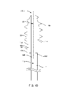
FIG. 1B is a side cross-sectional view of the example magnetically steerable
screw-
tip cannula of FIG. 1A.
FIG. 2 is a side view of another example magnetically steerable screw-tip
cannula
in accordance with the present disclosure.
FIG. 3 is a side view of yet another example magnetically steerable screw-tip
cannula in accordance with the present disclosure.
FIG. 4 is a schematic view of an example system including a magnetically
steerable
screw-tip cannula being inserted into biological tissue, in accordance with
the present
disclosure.
FIG. 5 is a flowchart illustrating an example method of using a magnetically
steerable screw-tip cannula in accordance with the present disclosure.
FIG. 6 is a cross-sectional view of an example magnetically steerable screw-
tip
cannula being used to treat biological tissue in accordance with the present
disclosure.
These drawings are provided to illustrate various aspects of the invention and
are
not intended to be limiting of the scope in terms of dimensions, materials,
configurations,
arrangements or proportions unless otherwise limited by the claims.
DETAILED DESCRIPTION
While these exemplary embodiments are described in sufficient detail to enable
those skilled in the art to practice the invention, it should be understood
that other
embodiments may be realized and that various changes to the invention may be
made
without departing from the spirit and scope of the present invention. Thus,
the following
more detailed description of the embodiments of the present invention is not
intended to
3
CA 03231446 2024- 3- 11
WO 2023/039282
PCT/US2022/043325
limit the scope of the invention, as claimed, but is presented for purposes of
illustration
only and not limitation to describe the features and characteristics of the
present invention,
to set forth the best mode of operation of the invention, and to sufficiently
enable one skilled
in the art to practice the invention. Accordingly, the scope of the present
invention is to be
defined solely by the appended claims.
Definitions
In describing and claiming the present invention, the following terminology
will be
used.
The singular forms "a,- "an," and "the" include plural referents unless the
context
clearly dictates otherwise. Thus, for example, reference to "a channel"
includes reference
to one or more of such channels and reference to "the magnet" refers to one or
more of such
magnets.
As used herein with respect to an identified property or circumstance,
"substantially- refers to a degree of deviation that is sufficiently small so
as to not
measurably detract from the identified property or circumstance. The exact
degree of
deviation allowable may in some cases depend on the specific context.
As used herein, "adjacent" refers to the proximity of two structures or
elements.
Particularly, elements that are identified as being "adjacent" may be either
abutting or
connected. Such elements may also be near or close to each other without
necessarily
contacting each other. The exact degree of proximity may in some cases depend
on the
specific context.
As used herein, the term "about" is used to provide flexibility and
imprecision
associated with a given term, metric or value. The degree of flexibility for a
particular
variable can be readily determined by one skilled in the art. However, unless
otherwise
enunciated, the term "about" generally connotes flexibility of less than 2%,
and most often
less than 1%, and in some cases less than 0.01%.
As used herein, a plurality of items, structural elements, compositional
elements,
and/or materials may be presented in a common list for convenience. However,
these lists
should be construed as though each member of the list is individually
identified as a
separate and unique member. Thus, no individual member of such list should be
construed
as a de facto equivalent of any other member of the same list solely based on
their
presentation in a common group without indications to the contrary.
4
CA 03231446 2024- 3- 11
WO 2023/039282
PCT/US2022/043325
As used herein, the term "at least one of' is intended to be synonymous with
"one
or more of." For example, "at least one of A, B and C" explicitly includes
only A, only B,
only C, or combinations of each.
Numerical data may be presented herein in a range format. It is to be
understood
that such range format is used merely for convenience and brevity and should
be interpreted
flexibly to include not only the numerical values explicitly recited as the
limits of the range,
but also to include all the individual numerical values or sub-ranges
encompassed within
that range as if each numerical value and sub-range is explicitly recited. For
example, a
numerical range of about 1 to about 4.5 should be interpreted to include not
only the
explicitly recited limits of 1 to about 4.5, but also to include individual
numerals such as 2,
3, 4, and sub-ranges such as 1 to 3, 2 to 4, etc. The same principle applies
to ranges reciting
only one numerical value, such as "less than about 4.5," which should be
interpreted to
include all of the above-recited values and ranges. Further, such an
interpretation should
apply regardless of the breadth of the range or the characteristic being
described.
Any steps recited in any method or process claims may be executed in any order
and are not limited to the order presented in the claims. Means-plus-function
or step-plus-
function limitations will only be employed where for a specific claim
limitation all of the
following conditions are present in that limitation: a) "means for" or "step
for" is expressly
recited; and b) a corresponding function is expressly recited. The structure,
material or acts
that support the means-plus function are expressly recited in the description
herein.
Accordingly, the scope of the invention should be determined solely by the
appended
claims and their legal equivalents, rather than by the descriptions and
examples given
herein.
Examplc Embodimcnts
As explained above, it can be difficult to safely reach certain portions of
brain tissue
using a straight cannula. Steerable cannulas have been developed as one way to
address
this issue. Steerable cannulas can use curvilinear paths in the body to enable
access to
anatomical targets that are not safely accessible by straight cannulas.
Steerable cannulas,
of a variety of designs, have received a great deal of attention for potential
therapeutic
applications in soft tissue such as the liver, lungs, kidneys, prostate, and
brain. Steerable
cannulas have the potential to decrease the risk of access (and subsequent
biopsy or therapy
delivery) deep in the brain by enabling steering around sensitive structures
such as
vasculature. Their ability to curve in tissue also enables honing in on the
target during
5
CA 03231446 2024- 3- 11
WO 2023/039282
PCT/US2022/043325
deployment, potentially improving diagnostic yield. Further, as they can curve
in tissue,
steerable cannulas may provide the ability to more closely match the volume of
non-linearly
shaped anatomical features, such as tumors, during multi-step therapy
delivery.
Existing steerable cannula designs are insufficient for deployment in the
brain,
however. Many steerable-cannula designs are introduced into the body by
pushing the
cannulas at their proximal end into the tissue (as with traditional straight
instruments). The
cannulas can curve in the tissue, but pushing a curved cannula from its base
can introduce
significant forces on the surrounding tissue at the areas of curvature. In
particular, the force
applied to the base, or proximal end, of the cannula in order to insert the
cannula can cause
the curved portion of the cannula to push against surrounding tissue. These
forces can result
in damage to tissue via contusion or bleeding due to compression and can even
result in
events in which the tissue around the cannula fractures and the cannula shaft
cuts laterally
through the tissue causing significant damage.
Further, because of the shaft stiffness of these types of cannulas, which
allows them
to be pushed from their base through the tissue, the cannulas may not be
capable of
achieving tight radii of curvature. A recent state-of-the-art steerable-
cannula design,
specifically tailored to safely achieve tight steering curvature, produces a
radius of
curvature of approximately 60mm in ex vivo ovine brain and gelatin tissue
phantom.
Another notable, biologically inspired steerable cannula has been shown to
achieve
curvatures of ¨50 mm, but at the cost of a larger overall diameter of 2.5mm
with
significantly smaller working channels due to its segmented design. These
achievable
curvatures are still insufficient for dexterous navigation and therapy
delivery in the brain.
Another paradigm in steerable cannulas can be actuated via internal
mechanisms.
Examples include tendon-actuated cannulas and concentric tube robots. To
deploy deep in
sensitive tissue, these robots can employ a 'follow-the-leader' motion, in
which the robot's
shaft does not change shape after it has been embedded in the tissue. This is
possible for
these designs, but to do so severely limits the design and prevents them from
sufficiently
correcting their motion during deployment.
This disclosure describes a new type of steerable cannula that can provide
better
safety and flexibility compared to previous straight and steerable cannulas.
The steerable
cannulas described herein can be steered magnetically, and insertion force can
be provided
by a screw-tip so that the cannula is pulled from the tip instead of pushed
from outside the
biological tissue. The design can include a screw with a central lumen, which
serves as the
6
CA 03231446 2024- 3- 11
WO 2023/039282
PCT/US2022/043325
tip of the cannula. One or more magnets, such as axially magnetized ring
magnets (e.g.
NdFeB or comparable magnetic material) can be attached to the screw, and a
flexible
cannula tube can be towed behind the screw and magnets. The cannula can be
steered via
a robotically controlled external magnet (e.g., a spherical-actuator-magnet
manipulator
(SAMM) system), a manually controlled external magnet (e.g., using an image
guided-
surgery method, such as the TRAC method), or a set of stationary external
electromagnets
(e.g., an Omnimagnet, an OctoMag system, or similar). In some examples, the
magnetic
field can be generated by an omnidirectional magnet described in U.S. Patent
No.
10,199,147, which is incorporated herein by reference_ A robotic
insertion/rotation stage at
the proximal end of the tube (outside of the tissue) can rotate the tube (and
thus the screw).
The insertion/rotation stage can also advance the tube in a coordinated
fashion, based on
the pitch of the screw, to keep up with the pulling from the tip rather than
pushing the tip
forward. Alternatively, the rotation and/or insertion actions of this robotic
insertion/rotation
stage can be performed manually, rather than robotically, even as steering is
driven via the
external magnetic field.
The flexible cannula being pulled by the screw-tip can serve as a working
channel
after it is steered to the desired site in the brain for, e.g., biopsy tools,
targeted liquid drugs,
or ablation probes. Motion planning and image-based closed-loop control can be
used to
steer the cannula to a desired site.
The screw-tip flexible cannulas described herein can achieve smaller radii of
curvature than many existing devices while exerting less force on brain tissue
during
deployment. This can enable safer and more accurate access to sites deeper in
the brain due
to the ability to steer around sensitive anatomical structures, hone in on
targets, and match
anatomical volumes with multi-stage therapy delivery. The screw-tip flexible
cannulas can
also be used in other organs where similar procedures may be useful, such as
the liver and
the lungs.
With this general description in mind, FIG. 1A shows a side view of an example
magnetically steerable screw-tip cannula 100. This device includes a flexible
cannula 110
with a distal end 112 and a proximal end 114 opposite from the distal end. As
used herein,
the "distal" end of the cannula is the end that is inserted into biological
tissue, such as a
brain. The proximal end is the opposite end, which remains outside the
biological tissue
and outside the patient in most cases. FIG. 1B is a cross-sectional view of
the same
magnetically steerable screw-tip cannula. This figure shows an internal lumen
116
7
CA 03231446 2024- 3- 11
WO 2023/039282
PCT/US2022/043325
extending to the distal end 112 of the cannula. The device also includes a
magnetically
steerable screw-tip 120 on the distal end of the cannula. The screw-tip
includes a screw
body 122 with screw threads 124 on an exterior surface of the screw body. The
screw
threads have a helical shape and are oriented to generate insertion or
retraction force along
a longitudinal axis 126 of the screw bod when the screw body rotates. The
screw body also
includes an internal lumen 128 extending along the longitudinal axis of the
screw body.
This internal lumen is connected to the internal lumen of the flexible
cannula. The screw-
tip also includes magnets 130 attached to the screw body. One magnet or
multiples magnets
can be used, but this example includes two permanent magnets having a ring
shape,
attached to the screw body. The magnets have north poles 132 and south poles
134 oriented
so that the average magnetization direction (i.e., the vector from the south
pole to the north
pole) is substantially parallel to the longitudinal axis of the screw body.
The ring-shaped
magnets also have an internal lumen that is connected to the internal lumen of
the flexible
cannula and the internal lumen of the screw body. Thus, the internal lumens
provide a clear
pathway to deliver materials or instruments to a site at the tip of the screw-
tip.
The magnet in the magnetically steerable screw-tip can allow forces and torque
to
be applied to the screw-tip using a magnetic field. For example, a magnetic
field can be
applied by a magnetic field source located outside the biological tissue, and
this magnetic
field can exert a force and/or torque on the screw-tip inside the biological
tissue. As in the
example described above, the magnet can have an average magnetization that is
substantially parallel to the longitudinal axis of the screw body. When an
external magnetic
field is applied, the magnet in the screw-tip can tend to align its magnetic
field with the
external magnetic field. Therefore, the external magnetic field can be applied
in a desired
direction to cause the screw-tip of the cannula to move and/or rotate to align
with the
magnetic field direction. Thus, a force, or a torque, or both can be applied
to the screw-tip
using the external magnetic field. As a result, the magnetic steering can be
invariant with
respect to the current rotation of the cannula and screw-tip.
In some examples, the magnet in the screw-tip can be a permanent magnet. In
certain cases, the permanent magnet can be a rare-earth magnet. Materials that
can be used
in permanent magnets include iron, steel, nickel, cobalt, gadolinium,
dysprosium, ferrite,
alnico, neodymium, samarium, composites thereof, alloys thereof, and the like.
In one
example, the magnet can be a NdFeB permanent magnet. In other examples, the
magnet
can be made of a "soft" magnetic material that becomes magnetized in the
presence of an
8
CA 03231446 2024- 3- 11
WO 2023/039282
PCT/US2022/043325
applied magnetic field. Examples of soft magnetic materials include alloys of
iron, nickel,
cobalt, with elements such as boron, carbon, phosphorous, and silicon. As
mentioned
above, one magnet or multiple magnets can be used. For example, the screw-tip
can include
two, three, four, six, eight or more magnets. The magnets can be stacked
together or placed
in separate locations in or on the screw body. In certain examples, the
magnets can be
stacked at a proximal end (opposite from the tip) of the screw body. In
another alternative
example, the screw body can be formed of the magnets (i.e. the screw body can
be molded
or machined from a magnetic material).
The magnet or magnets of the screw-tip can include an internal lumen. The
internal
lumen of the magnets can be aligned with the internal lumen of the screw body
and the
internal lumen of the flexible cannula so that a clear pathway exists through
the flexible
cannula all the way to the tip of the screw-tip. In certain examples, the
magnet can be in
the shape of a ring or cylinder with an internal lumen in the center of the
ring of cylinder.
The internal lumen of the magnet can be coaxial with the internal lumen of the
screw body
and the internal lumen of the flexible cannula in some examples. In further
examples, the
magnet can be attached to the proximal end of the screw body and the internal
lumen of the
magnet can be directly connected to the internal lumen of the screw body. The
flexible
cannula can also be directly connected to the internal lumen of the magnet so
that fluid
delivery or instrument delivery can be accomplished through the flexible
cannula, then
through the internal lumen of the magnet, then through the internal lumen of
the screw
body. The magnet can be connected to the flexible cannula and to the screw
body by any
suitable attachment method, such as gluing, friction fitting, welding, and so
on. In other
examples, the flexible cannula can be inserted into or through the internal
lumen of the
magnet. The flexible cannula can also be inserted into or through the internal
lumen of the
screw body.
The magnet can have an internal lumen with a diameter from about 0.05 mm
about 5 mm in some examples, or from about 0.08 mm to about 3 mm, or from
about 0.1
mm to about 2 mm, or from about 0.5 mm to about L5 mm. In overall dimensions,
the
magnet can have an external diameter from about 0.08 mm to about 8 mm, or from
about
0.1 min to about 5 mm, or from about 0.5 mm to about 3 mm, or from about 1 mm
to about
2 mm. These dimensions can be for magnets having a circular shape. Magnets of
other
shapes can also be used, and may have similar dimensions for their width and
length. The
9
CA 03231446 2024- 3- 11
WO 2023/039282
PCT/US2022/043325
thickness of the magnet can be from about 0.05 mm to about 5 mm, or from about
0.1 mm
to about 3 mm, or from about 0.5 mm to about 2 mm, in some examples.
Magnets without an internal lumen can also be used. If the screw-tip includes
a
magnet without an internal lumen, then the magnet can be attached to the screw
body at a
location that does not block the internal lumen of the screw body or the
internal lumen of
the flexible cannula. For example, small magnets can be arranged around the
lumen of the
screw body. These can be attached to the exterior of the screw body, or to the
proximal end
of the screw body, or embedded into the screw body in various examples. In
certain
examples, a first magnet can be located nearer to the tip, or distal end, of
the screw body,
and a second magnet can be located nearer to the proximal end of the screw
body. The
magnets can be aligned so that their average magnetization is substantially
parallel to the
longitudinal axis of the screw body.
An electromagnet can also be used in the screw-tip instead of or in addition
to the
types of magnets described above. FIG. 2 shows an example magnetically
steerable screw-
tip cannula 100 that includes an electromagnet 130. The electromagnet includes
a coil of
wire wrapped around the flexible cannula 110. In other examples, the coil can
be wrapped
around the screw body 122 or another component such as a metal core or metal
or plastic
tube. In any of these examples, the electromagnet can be considered attached
to the screw
body as a part of the screw-tip 120. The coil can be connected to an electric
current source
to cause an electric current that generates a magnetic field from the coil.
The electric current
source can be a power supply that is external to the biological tissue in
which the cannula
is inserted, and the electromagnet can be connected to the power supply by
wires that run
along or through the cannula. Alternatively, the electromagnet can be
connected to a battery
that is in or attached to the screw tip or cannula. In this example, the
electromagnet can be
run continuously or selectively turned on when it is desired to apply a force
or torque to the
screw-tip. The current passing through the coil of the electromagnet can also
be controlled
to adjust the strength of the magnetic field generated by the electromagnet.
Using current
control requires a simpler model of the system for accurate control than would
be required
in voltage control. This can be used to adjust the force or torque exerted on
the screw tip
by an external magnetic field.
Additional magnets can also be located along the length of the flexible
cannula. For
example, additional ring-shaped magnets can be threaded on or embedded in the
cannula
with the cannula passing through the interior lumen of the ring-shaped
magnets. FIG. 3
CA 03231446 2024- 3- 11
WO 2023/039282
PCT/US2022/043325
shows an example magnetically steerable screw-tip cannula 100 that includes
additional
magnets 140 along the length of the flexible cannula 110. These additional
magnets can
provide additional control over the movement of the cannula when the cannula
is inserted
into biological tissue. For example, the individual magnets can be targeted
using an external
magnetic field to apply a force and/or torque to the individual magnets. In
certain examples,
a force can be applied that is parallel to the cannula to assist with
insertion or retraction of
the cannula. In other examples, a force can be applied that is perpendicular
to the cannula
to move the cannula in a sideways direction instead of in a forward, insertion
direction or
a backward, retraction direction. In one example, the additional magnets can
be oriented
having a polarization opposite to that of the primary magnets in the screw-
tip. The example
shown in FIG. 3 also includes a screw-tip 120 with a screw body 122 and
magnets 130 as
in the previous examples. The magnets in the screw-tip and the additional
magnets along
the length of the flexible cannula can be the same type of magnets or
different types of
magnets, and may be any of the types of magnets described above.
If magnets are included along the length of the cannula, these additional
magnets
can have similar dimensions to the magnet dimensions described above. The
magnets can
be spaced apart along the cannula at a spacing distance from about 5 mm to
about 10 cm in
some examples, or from about 100 mm to about 5 cm, or from about 1 cm to about
3 cm.
It is noted that the flexible cannulas shown in the drawings are not drawn to
scale,
and the flexible cannula can often be much longer compared to the length of
the screw-tip.
In various examples, the flexible cannula can have a length from about 5 cm to
about 100
cm, or from about 8 cm to about 80 cm, or from about 10 cm to about 50 cm, or
from about
10 cm to about 30 cm. The inner diameter of the cannula can be from about 0.05
mm to
about 5 mm in some examples, or from about 0.08 mm to about 3 mm, or from
about 0.1
mm to about 2 mm, or from about 0.5 mm to about 1.5 mm. The outer diameter of
the
cannula can be from about 0.08 mm to about 8 mm, or from about 0.1 mm to about
5 mm,
or from about 0.5 mm to about 3 mm, or from about 1 mm to about 2 mm.
The flexible cannula can be formed of any material which is biocompatible and
provides sufficient mechanical integrity to transfer torque to the screw-tip
while also
avoiding or minimizing damage to contacted tissue. Non-limiting examples of
suitable
materials can include polymer material such as PT-FE TYGON, and the like,
metal
material, composites, and the like. For example, rigid metal may be segmented
and held
together via flexible linkages such as polymer links, metal links, or the
like. In certain
11
CA 03231446 2024- 3- 11
WO 2023/039282
PCT/US2022/043325
examples, the flexible cannula can be machined to increase its compliance,
such as by
reducing sidewall thickness, selective patterning (e.g. laser etching
patterns), and/or
selective removal (e.g. notches). As a general guideline, the flexible cannula
can be
designed with the goal of achieving high torsional stiffness and low bending
stiffness.
The screw body can similarly be formed of a suitable biocompatible material.
Generally, the screw body can be formed of a material which is more rigid than
the cannula,
and in some cases is non-flexible. Non-limiting examples can include brass,
stainless steel,
titanium, aluminum, Nitinol, and hard plastics such as ABS, PVC,
polypropylene,
polycarbonate, polystyrene, polyethylene, polyurethane, PET, DELRIN (available
from
DuPont, USA), and the like.
The screw body can have an outer diameter that is similar to or slightly
larger than
the flexible cannula. The outer diameter of the screw body can be defined as
the outer
diameter at the widest portion of the screw body, not including the screw
threads. The screw
threads can extend further out from the outer diameter of the screw body. In
some examples,
the outer diameter of the screw body can be from inner diameter of the cannula
can be from
about 0.08 mm to about 8 mm, or from about 0.1 mm to about 5 mm, or from about
0.5
mm to about 3 mm, or from about 1 mm to about 2 mm. The screw body can have an
internal lumen as explained above. The inner diameter of the screw body can be
from about
0.05 mm to about 5 mm in some examples, or from about 0.08 mm to about 3 mm,
or from
about 0.1 mm to about 2 mm, or from about 0.5 mm to about 1.5 mm.
The screw threads of the screw body can extend outward by a distance from
about
0.04 to about 4 mm, or from about 0.08 to about 3 mm, or from about 0.1 to
about 2 mm,
or from about 0.5 to about 2 mm. The screw threads can have any suitable
shape. The
examples shown in the figures have screw threads with a truncated triangular
cross-section.
In other examples, the screw can have a sharp pointed cross-section, or a
rounded cross-
section, a square cross-section, or other shaped cross-section. The threads
can have any
suitable pitch, such as from 0.05 mm to 3 mm, or from 0.08 mm to 2.5 mm, or
from 0.1
mm to 2 mm, or from 0.5 mm to L5 mm. The screw body can also have a tapered
distal
end or tip to help penetrate into biological tissue.
In addition to the magnetically steerable screw-tip cannulas themselves, the
present
disclosure also describes systems that include the steerable cannulas and
which can be used
to perform procedures using the steerable cannulas. In some examples, such
systems can
include a magnetically steerable screw-tip cannula and a torque applying
mechanism. The
12
CA 03231446 2024- 3- 11
WO 2023/039282
PCT/US2022/043325
torque applying mechanism can be located at a position toward the proximal end
of the
flexible cannula, outside the biological tissue. The torque applying mechanism
can apply
torque to the flexible cannula outside the biological tissue, and because the
cannula has a
high torsional stiffness the torque can be transferred to the screw-tip at the
distal end of the
cannula. The torque can cause the screw-tip to spin, which can generate
insertion force or
retraction force depending on the direction of spinning.
An example system 200 is shown in FIG. 4. This system includes a magnetically
steerable screw-tip cannula 100 as described above. The cannula is fed into
biological tissue
210 by a torque applying mechanism 220, which applies mechanical torque to the
flexible
cannula 110 at a location outside the biological tissue. The flexible cannula
transfers the
torque to a magnetically steerable screw-tip 120 to generate insertion or
retraction force. A
force sensor 222 is also included in this example. The force sensor can
measure the
mechanical torque applied to the flexible cannula. A magnetic field source 230
is positioned
to generate a magnetic field impinging upon the magnet 130 of the magnetically
steerable
screw-tip cannula. The magnetic field can generate a force or torque on the
screw-tip to
cause deformation of the cannula and to steer the cannula. A location sensor
240 is
positioned to locate the magnetically steerable screw-tip in the biological
tissue. Locating
the screw-tip in the tissue can be helpful for steering the screw-tip and
avoiding certain
sensitive portions of the tissue. The system also includes a controller 250.
The controller is
electrically connected to the torque applying mechanism, the force sensor, the
location
sensor, and the magnetic field source. These electrical connections are
represented by
dashed lines in the figure. The controller can be programmed to coordinate
insertion or
retraction of the cannula and magnetic steering via closed-loop control.
It is noted that the systems described herein can include various components
to
automate aspects of procedures performed using the steerable cannulas. For
example, the
torque applying mechanism can automate the application of torque to the
cannula.
However, this can also be done manually by a healthcare provider such as a
surgeon
manually rotating the proximal end of the cannula. Whether the torque is
applied manually
or by a mechanism, the torque can be applied at a location outside the
biological tissue, i.e.,
outside the brain when the steerable cannula is inserted into the brain. Other
aspects of
procedures can also be performed manually or in an automated fashion by adding
various
components to the system. Several such components are described below.
13
CA 03231446 2024- 3- 11
WO 2023/039282
PCT/US2022/043325
The forces exerted by the flexible cannula on surrounding tissue can be
smaller
compared to steerable cannulas that are pushed into the tissue during
insertion. When the
insertion force is provided by pushing the cannula, the cannula can exert
large stresses on
the tissue in places where the cannula has curved due to steering. This can
damage the
tissue and cut through the tissue of the force is large enough. In contrast,
the magnetically
steerable screw-tip cannulas described herein do not derive the insertion
force from pushing
the cannula into the tissue. Rather, the insertion force is generated by the
rotation of the
screw-tip. The screw-tip moves forward during insertion because of the motion
of the screw
threads. Thus, the screw-tip pulls the flexible cannula behind it. Because the
flexible
cannula can be highly flexible (having a low bending stiffness), the flexible
cannula does
not exert a large force on the surrounding tissue as it is pulled behind the
screw-tip.
In some examples, a smaller mechanical force, parallel to the lumen of the
flexible
cannula, can be applied to the flexible cannula from outside the tissue to
help feed the
flexible cannula into the tissue. However, the screw-tip can provide a
majority of the
insertion force for inserting the cannula into the tissue, and the additional
force applied to
the cannula from outside the tissue can be merely for the purpose of matching
the speed of
the screw-tip. Applying this additional mechanical force to the cannula from
outside the
tissue can help to further reduce stress placed on the tissue by the cannula
as the cannula is
inserted. Similarly, a mechanical retraction force can be applied to the
cannula outside the
tissue while the screw-tip is also rotated to generate a retraction force. The
mechanical force
applied to the cannula outside the tissue can be applied manually or by the
torque applying
mechanism described above.
The torque applying mechanism can include any suitable mechanism for applying
mechanical torque to the flexible cannula. In various examples, the torque
applying
mechanism can include an electric motor, a pneumatic actuator, a piezoelectric
actuator, or
a combination thereof. In some examples, the flexible cannula can be fed
through the torque
applying mechanism as the torque is applied to the flexible cannula. In other
examples, the
torque applying mechanism can be fixed to the flexible cannula by clamping or
another
attachment method and the torque applying mechanism can move together with the
cannula
as the cannula is inserted or retracted. The torque applying mechanism can
apply torque to
the cannula in a direction parallel to the lumen of the cannula (i.e., the
longitudinal axis of
the cannula). The direction of a torque vector can be defined using the "right
hand rule,"
which states that the torque vector has a direction pointing perpendicular to
the plane of
14
CA 03231446 2024- 3- 11
WO 2023/039282
PCT/US2022/043325
rotation. This vector can be parallel to the lumen of the cannula. The
direction of the vector
can depend on the direction of rotation of the cannula.
The torque applying mechanism can also apply a force parallel to the lumen of
the
cannula, as explained above. In some examples, this force can have a magnitude
from about
0.001 N to about 1 N. The system may also include a force sensor to measure
the force
and/or torque applied to the cannula. The force sensor can be integrated as a
part of the
torque applying mechanism or the force sensor can be a separate component.
The speed of insertion and retraction of the cannula can be controlled to be
in a safe
range for the particular procedure being performed. In some examples, the
speed at which
the screw-tip proceeds through the biological tissue during insertion can be
from about 0.5
cm/minute to about 10 cm/minute, or from about 0.5 cm/minute to about 5
cm/minute, or
from about 0.5 cm/minute to about 2 cm/minute, and in some cases up to 2
cm/sec. Similar
speeds can be used when retracting the cannula from the biological tissue.
In more detail regarding the magnetic field source, in some examples the
magnetic
field source can include a permanent magnet. The permanent magnet can be
oriented
adjacent to the biological tissue and rotated and translated to affect the
force and torque
that are imparted on the magnet located at the screw-tip of the cannula. The
pose of the
permanent magnet can be controlled by a robot or manually. Alternatively, the
magnetic
field source can be an electromagnet. The electromagnet can be rotated and
translated to
affect the force and torque that are imparted on the magnet at the screw-tip
of the cannula.
Further, the electromagnet can be varied in magnetic field strength as an
additional variable
which can be used to actively control movement of the magnet at the screw-tip.
For
example, the electromagnet can have at least one current that is controlled to
affect the
force and torque that are imparted on the magnet at the screw-tip of the
cannula. As with
the permanent magnet, the electromagnet can be controlled by a robot or
manually. In
certain examples, the magnetic field source can include an omnidirectional
magnet such as
an Omnimagnet system, OctoMag system, or a system as described in U.S. Patent
No.
10,199,147. In another example, the magnetic field source can be a tri-axial
Helmholtz
coil. In certain examples, the magnetic field source can include multiple sets
of wire coils
oriented in different directions. The electric current through the wire coils
can be controlled
to generate magnetic fields oriented in different directions. The overall
effective magnetic
field of this magnetic field source can depend on the combination of the
magnetic fields
CA 03231446 2024- 3- 11
WO 2023/039282
PCT/US2022/043325
generated by the coils. Thus, an overall magnetic field can be generated with
various
orientations and magnetic field strengths.
The magnetic field strength generated by the magnetic field source can be from
0.1
mT to 100 mT at the location of the screw-tip of the cannula, and in some
cases up to 8 T
or higher, e.g. when using an MRI system as the magnetic field source. The
magnetic field
can be used to attract the magnets in the screw-tip, repel the magnets in the
screw tip, to
apply a torque to the magnets in the screw tip, or a combination of these.
However, it is
noted that in some examples the magnetic field source is not used to rotate
the screw-tip
around its longitudinal axis. The torque used to rotate the screw-tip around
its longitudinal
axis comes from the mechanical torque applied to the flexible cannula outside
the biological
tissue. Any torque applied to the screw-tip by the magnetic field source can
be for the
purpose of steering the screw tip.
A location sensor can be included in the system to locate the screw-tip within
the
biological tissue. In some examples, the location sensor can be a magnetic
sensor that can
provide orientation and location information about the screw-tip based on the
magnets
present in the screw-tip. In other examples, the location sensor can include a
medical
imaging device such as an X-ray device, a fluoroscopy device, a tomography
device, an
ultrasound sonography device, or a magnetic resonance imaging device. A
magnetic
resonance imaging device can be used if the magnet in the screw-tip is an
electromagnet
that may be turned off before the magnetic resonance imaging device is used.
Any of these
sensors can locate the screw-tip within the biological tissue. The sensor can
be used
periodically to locate the screw-tip, or the sensor can be turned on
continuously to provide
a real-time location of the screw-tip.
The system can also include a controller that can be electronically connected
to
some or all of the electronic components in the system. The controller can
coordinate
insertion of the cannula, retraction of the cannula, magnetic steering of the
screw-tip, or a
combination thereof. In some examples, the controller can be electronically
connected to
the torque applying mechanism, the force sensor, the location sensor, the
magnetic field
source, or a combination thereof. The controller can utilize closed-loop
control, for example
by signals to the torque applying mechanism to apply torque to the cannula,
and adjusting
the signals based on readings from the force sensor. In another example, the
controller can
adjust the placement, direction, and electric current to the magnetic field
source based on
readings from the location sensor. The controller can be programmed to insert
the cannula
16
CA 03231446 2024- 3- 11
WO 2023/039282
PCT/US2022/043325
along a desired pathway into biological tissue. The controller can also
include a user
interface to allow a user, such as a surgeon, to directly control the
direction and speed of
the screw-tip as the screw-tip cannula is inserted or retracted.
The present disclosure also describes methods of using magnetically steerable
screw-tip cannulas. In some examples, a magnetically steered screw-tip cannula
device can
be inserted into a biological tissue such as a brain or other organ. The
device can include a
flexible cannula with a screw-tip having a magnet. The flexible cannula can be
deformable
by forces that can be safely imparted by biological tissue. The screw-tip can
be located at
a distal tip of the cannula, with an internal lumen that is substantially
parallel with the screw
axis and with the lumen of the cannula. The magnet can also be located near
the distal tip
of the cannula. The magnet can also have an internal lumen that is
substantially parallel
with the lumen of the cannula. The average magnetization of the magnet can be
substantially parallel to the lumen. The lumens of the cannula, magnet, and
screw-tip can
form a continuous lumen. Mechanical torque can be applied parallel to the
lumen of the
cannula, at a position on the cannula outside of the biological tissue, to
cause the cannula
and its screw tip to rotate to generate insertion or retraction motion due to
the screw. A
magnetic field source can be disposed adjacent to the biological tissue so
that a magnetic
field produced by the magnetic field source impinges upon the magnet at the
screw-tip of
the cannula, leading to force and/or torque that cause deformation of the
flexible cannula
to steer the cannula through the tissue.
FIG. 5 is a flowchart illustrating and example method 300 of using a
magnetically
steerable screw-tip cannula. The method includes: inserting a magnetically
steerable
screw-tip cannula into biological tissue, wherein the magnetically steerable
screw-tip
cannula comprises a flexible cannula comprising a distal end that is inserted
into the
biological tissue and an internal lumen extending to the distal end, and a
magnetically
steerable screw-tip on the distal end of the cannula, the screw-tip comprising
a screw
body having screw threads on an exterior surface thereof and an internal lumen
extending
along a longitudinal axis of the screw body, wherein the internal lumen is
connected to
the internal lumen of the cannula, the screw-tip further comprising a magnet
attached to
the screw body 310; applying mechanical torque to the flexible cannula at a
location
outside the biological tissue, wherein the cannula transfers the torque to the
screw-tip
such that the screw-tip rotates and the screw threads generate insertion or
retraction force
along the longitudinal axis of the screw body 320; and applying a magnetic
field from a
17
CA 03231446 2024- 3- 11
WO 2023/039282
PCT/US2022/043325
magnetic field source positioned outside the biological tissue, wherein the
magnetic field
impinges upon the magnet of the magnetically steerable screw-tip cannula to
generate a
force or torque causing a deformation of the cannula to steer the cannula 330.
Methods of using magnetically steerable screw-tip cannulas can include using
any
of the components of the cannula devices and systems described above. In a
particular
example, a method of using a magnetically steerable screw-tip cannula can
include
controlling an electric current to an electromagnet that acts as a magnetic
field source for
steering the screw-tip cannula. Controlling the electric current can allow the
strength of
the magnetic field to be adjusted, which can provide finer control over
magnetic steering
of the screw-tip. Additionally, as mentioned above, some types of magnets
include
multiple coils that generate electric fields in different directions. The
electric current
through multiple coils can be controlled independent to allow the strength and
direction
of the overall magnetic field to be adjusted. In a particular example, the
magnetic field
source can include three wire coils that generate electric fields oriented in
three mutually
orthogonal directions. By independently controlling the electric current
passing through
these three coils, an overall magnetic field can be generated with any desired
direction
and strength.
In other examples, the magnetic field source can include a permanent magnet.
Whether the magnetic field source is a permanent magnet or an electromagnet,
it can be
useful to move the magnetic field source in relation to the screw-tip to
change the
magnetic field strength and direction applied to the screw-tip. The movement
of the
magnetic field source can include translational movements, rotational
movements, and
combinations thereof. The methods described herein can include translating,
rotating, or
both translating and rotating the magnetic field source in order to affect the
force and/or
torque that is imparted to the magnet of the screw-tip cannula. The rotation
and
translation can be performed manually or by a robot. Examples of robot systems
that can
be useful for moving the magnetic field source include robotic arms and any
other system
with sufficient degrees of freedom to translate and rotate the magnetic field
source with
respect to the screw-tip.
The methods described above can also include locating the screw-tip using a
location sensor. In one example, the screw-tip can be located at discrete time
intervals and
then the screw-tip can be moved by insertion, retraction, magnetic steering,
or a
combination thereof, between the times of locating. In another example, the
location of
18
CA 03231446 2024- 3- 11
WO 2023/039282
PCT/US2022/043325
the screw-tip can be continuously monitored while the screw-tip is inserted,
retracted,
magnetically steered, or a combination thereof. The screw-tip can be located
using any of
the location sensors described above.
The magnetically steerable screw-tip cannulas can be particularly useful for
insertion into the brain to allow access to deep portions of brain while
avoiding sensitive
portions of the brain. The cannulas can also be useful for procedures
involving other
biological tissues, such as the lungs, spinal column, eyes, liver, pancreas,
kidney, prostate,
gastrointestinal tract, urinary tract, and others. The cannula devices and
systems described
above can all be used for any of these tissues.
Methods can also include using the cannula after the cannula has been inserted
to
a desired location in the biological tissue. The lumen of the cannula can be
useful for
delivering materials such as fluids to the tissue, or draining fluids from the
tissue, or as a
working channel for instruments, or to biopsy the tissue. In certain examples,
a treatment
fluid can be delivered through the cannula. Certain treatments can be useful
to treat a
specific area of the tissue, such as a tumor, infected area, and so on.
However, it may be
harmful to deliver the treatment, such as chemotherapy, radiation,
antibiotics, etc., to
healthy tissue. The magnetically steerable cannulas described herein can be
useful for
delivering such treatments directly to the affected areas of the tissue while
reducing
delivery to healthy tissue. In some cases, the internal lumen can be
selectively blocked
(e.g. blocked during insertion and then unblocked post insertion). This can
prevent entry
of undesired fluids or debris during insertion, for example. In additional
alternatives, the
internal lumen can be filled with an instrument. For example, ablation tools,
sensing
instruments, electrical stimulation instruments, electrical monitoring
instruments, and
others, can be permanently oriented within the internal lumen.
FIG. 6 shows an example of using a magnetically steerable screw-tip cannula
100
to deliver a treatment to a tumor 212 in a brain 214. The treatment can be a
fluid
delivered through the tip of the cannula. As the screw-tip 120 advances
through the brain,
the screw-tip can be steered to pass through the tumor. In this example, the
tumor has an
irregular shape. The treatment can be delivered to multiple treatment volumes
216 along
the path of the cannula, either as the cannula is being inserted or as the
cannula is being
retracted. These roughly spherical treatment volumes form a "snowman volume
that
closely matches the irregular shape of the tumor. Forming such a treatment
volume would
be difficult or impossible with a straight cannula. Thus, the steerable
cannula described
19
CA 03231446 2024- 3- 11
WO 2023/039282
PCT/US2022/043325
herein can allow for a safer treatment with less exposure of healthy brain
tissue to the
treatment fluid.
The flexible cannula can be designed to have a low bending stiffness so that
the
cannula can flex with a small radius of curvature. Smaller radii of curvature
can allow the
cannula to be steered to match irregular treatment volumes or to precisely
avoid sensitive
tissues. In some examples, the magnetically steerable screw-tip cannulas
described herein
can be steered with a minimum radius of curvature from 5 mm to 50 mm, or from
5 mm to
30 mm, or from 5 mm to 20 mm.
EXAMPLES
A prototype magnetically steerable screw-tip cannula was constructed having a
design similar to the design shown in FIG. 1A-1B. The device was steered
through an Agar
gel-based tissue phantom and an ex vivo ovine brain. The prototype was
composed of a
hollow, 3-mm-long brass screw, connected to four 0.5-mm-long round, hollow
ring
magnets stacked, pulling a hollow PTBE tube. The insertion in the gel phantom
was
performed using an electric, mechatronic device which inserted and rotated the
tube to drive
the cannula forward, and a robotic device holding an external permanent magnet
applying
a magnetic torque to steer the cannula in an arc. Control of the cannula in
the gel was
performed with a human aligning the external permanent magnet via a software
interface
and advancing the screw via a software interface controlling the electric
mechatronic
system. The insertion in the ex vivo ovine brain was performed with manual
insertion and
rotation, i.e., a human held the tube near the insertion point and rotated it
with their fingers.
Steering was performed in the ovine brain with the same robotically controlled
external
permanent magnet.
Control of the external magnet was performed automatically using an open loop
model of the cannula' s kinematics, i.e., the expected turning radius observed
in gel.
While the flowcharts presented for this technology may imply a specific order
of
execution, the order of execution may differ from what is illustrated. For
example, the
order of two more blocks may be rearranged relative to the order shown.
Further, two or
more blocks shown in succession may be executed in parallel or with partial
parallelization.
In some configurations, one or more blocks shown in the flow chart may be
omitted or
skipped. Any number of counters, state variables, warning semaphores, or
messages might
CA 03231446 2024- 3- 11
WO 2023/039282
PCT/US2022/043325
be added to the logical flow for purposes of enhanced utility, accounting,
performance,
measurement, troubleshooting or for similar reasons.
Modules may also be implemented in software for execution by various types of
processors. An identified module of executable code may, for instance,
comprise one or
more blocks of computer instructions, which may be organized as an object,
procedure, or
function. Nevertheless, the executables of an identified module need not be
physically
located together, but may comprise disparate instructions stored in different
locations
which comprise the module and achieve the stated purpose for the module when
joined
logically together.
The devices described herein may also contain communication connections or
networking apparatus and networking connections that allow the devices to
communicate
with other devices. Communication connections are an example of communication
media.
Communication media typically embodies computer readable instructions, data
structures,
program modules and other data in a modulated data signal such as a carrier
wave or other
transport mechanism and includes any information delivery media. A "modulated
data
signal" means a signal that has one or more of its characteristics set or
changed in such a
manner as to encode information in the signal. By way of example and not
limitation,
communication media includes wired media such as a wired network or direct-
wired
connection and wireless media such as acoustic, radio frequency, infrared and
other
wireless media. The term computer readable media as used herein includes
communication
media.
Reference was made to the examples illustrated in the drawings and specific
language was used herein to describe the same. It will nevertheless be
understood that no
limitation of the scope of the technology is thereby intended. Alterations and
further
modifications of the features illustrated herein and additional applications
of the examples
as illustrated herein are to be considered within the scope of the
description.
Furthermore, the described features. structures, or characteristics may be
combined
in any suitable manner in one or more examples. In the preceding description,
numerous
specific details were provided, such as examples of various configurations to
provide a
thorough understanding of examples of the described technology. It will be
recognized,
however, that the technology may be practiced without one or more of the
specific details,
or with other methods, components, devices, etc. In other instances, well-
known structures
21
CA 03231446 2024- 3- 11
WO 2023/039282
PCT/US2022/043325
or operations are not shown or described in detail to avoid obscuring aspects
of the
technology.
Although the subject matter has been described in language specific to
structural
features and/or operations, it is to be understood that the subject matter
defined in the
appended claims is not necessarily limited to the specific features and
operations described
above. Rather, the specific features and acts described above are disclosed as
example
forms of implementing the claims. Numerous modifications and alternative
arrangements
may be devised without departing from the spirit and scope of the described
technology.
22
CA 03231446 2024- 3- 11