Note: Descriptions are shown in the official language in which they were submitted.
- 1 -
"APPARATUS FOR PRODUCING ELECTRICAL ENERGY FROM WATER
CURRENTS"
* * * * *
FIELD OF THE INVENTION
The present invention concerns an apparatus for producing electrical energy
from water currents, for example water currents present in seas, lakes, rivers
or
other environments where there may be a water current.
BACKGROUND OF THE INVENTION
It is known that apparatuses exist for producing electrical energy from water
currents, substantially consisting of a central floating unit on the sides of
which
further units are disposed, equipped with hydrokinetic turbines that rotate
under
the effect of the water current, for example a sea water current. Each of the
turbines
is then connected to the rotor of an electric generator.
The hydrokinetic turbines can be equipped with two or more blades that rotate
about a certain axis which is substantially aligned with the direction of the
sea
current.
Although some known systems provide an automatic and passive alignment of
the hydrokinetic turbines with respect to the direction of the sea current,
providing
for example that the apparatus is anchored to the seabed by means of mooring
cables, the alignment and the stability of the apparatus are not always
optimal.
Consequently, the efficiency of the apparatus in terms of conversion of
kinetic
energy into electrical energy can be compromised by this lack of alignment and
stability; furthermore, the forces acting above all on the central floating
unit,
following the drive of the hydrokinetic turbines by the water current, can be
considerable. Known apparatuses can also prove to be rather heavy and bulky.
There is therefore a need to perfect an apparatus for producing electrical
energy
from water currents that can overcome at least one of the disadvantages of the
state
of the art.
In particular, one purpose of the present invention is to provide an apparatus
for
producing electrical energy from water currents that is light and efficient,
and
allows to obtain electrical energy from the motion of a water current in a
simple
way.
Another purpose of the present invention is to provide an apparatus for
CA 03231894 2024-3- 14
- 2 -
producing electrical energy from water currents that allows a stable and
effective
alignment of the hydrokinetic turbines used with the direction of the water
current.
Another purpose of the present invention is to provide an apparatus for
producing electrical energy from water currents that has limited bulk and in
which
the forces involved do not cause a lack of stability or balance thereof.
The Applicant has devised, tested and embodied the present invention to
overcome the shortcomings of the state of the art and to obtain these and
other
purposes and advantages.
SUMMARY OF THE INVENTION
The present invention is set forth and characterized in the independent claim.
The dependent claims describe other characteristics of the present invention
or
variants to the main inventive idea.
In accordance with the above purposes, an apparatus for producing electrical
energy comprises a device for converting the kinetic energy of a water current
into
electrical energy, provided with a first float on the sides of which there is
positioned a plurality of casings equipped with turbines, each turbine being
connected to an electric generator housed in the casings.
According to one characteristic aspect of the invention, the converter device
is
connected by means of first connection elements to an alignment device,
connected
on one side and by means of second connection elements to a second float and
on
the other side and by means of third connection elements to anchoring means;
the
alignment device is configured to allow the turbines to automatically align
with
the direction of the water current.
Advantageously, by means of the alignment device as above associated with the
converter device, it is possible to create an apparatus for producing
electrical
energy from water currents that allows a stable and effective alignment of the
turbines with the direction of the water current, therefore it allows to
effectively
convert the kinetic energy of the sea current into mechanical energy and then
into
electrical energy thanks to the electric generators coupled to the turbines.
According to another aspect of the invention, the alignment device comprises
an external ring, to which the first connection elements are connected, the
external
ring rotating with respect to a fixed internal pin to which the second and
third
connection elements are connected.
CA 03231894 2024-3- 14
- 3 -
According to another aspect of the invention, the external ring rotates with
respect to the internal pin about an axis that is substantially orthogonal to
the
direction of the sea current.
According to another aspect of the invention, rolling means are positioned
between the internal pin and the external ring.
According to another aspect of the invention, the first connection elements
comprise at least one cable for connecting the first float to the external
ring.
According to another aspect of the invention, the first connection elements
comprise at least one rod for connecting each of the casings to the external
ring.
According to another aspect of the invention, the second connection elements
comprise a plurality of ropes attached on one side to the internal pin and on
the
other side to the second float.
According to another aspect of the invention, the third connection elements
comprise a plurality of ropes attached on one side to the internal pin and on
the
other side to the anchoring means.
According to another aspect of the invention, the second and third connection
elements are connected respectively to opposite ends of the internal pin.
According to another aspect of the invention, the converter device is equipped
with a bulb positioned underneath the first float.
According to another aspect of the invention, the first float is substantially
coplanar to the casings, and it is connected to them by means of structures
which
can have sections with a shape similar to wing profiles, or fairings similar
to wing
pro files.
According to another aspect of the invention, this first float contains inside
it a
plurality of watertight chambers which can contain air or water or a
combination
of the two with corresponding pumps and transfer valves, thus allowing to
manage
the upward buoyancy force and therefore the overall configuration of the
converter
device, as occurs in submarines for example.
DESCRIPTION OF THE DRAWINGS
These and other aspects, characteristics and advantages of the present
invention
will become apparent from the following description of some embodiments, given
as a non-restrictive example with reference to the attached drawings wherein:
- fig. 1 is a schematic lateral view of an apparatus for producing electrical
energy
CA 03231894 2024-3- 14
- 4 -
from water currents according to the present invention;
- fig. 2 is a three-dimensional view of a converter device provided in the
present
apparatus;
- fig. 3 is a schematic three-dimensional view of an alignment device of
the present
apparatus;
- fig. 4 is a schematic plan view of a mode of alignment of the present
apparatus
with respect to a sea current;
- fig. 5 is a first three-dimensional view of the present apparatus;
- fig. 6 is a second three-dimensional view of the present apparatus;
- fig. 7 is another three-dimensional view of the present apparatus.
To facilitate comprehension, the same reference numbers have been used, where
possible, to identify identical common elements in the drawings. It is
understood
that elements and characteristics of one embodiment can be conveniently
combined or incorporated into other embodiments without further
clarifications.
DESCRIPTION OF SOME EMBODIMENTS
We will now refer in detail to the possible embodiments of the invention, of
which one or more examples are shown in the attached drawings, by way of a non-
limiting illustration. The phraseology and terminology used here is also for
the
purposes of providing non-limiting examples.
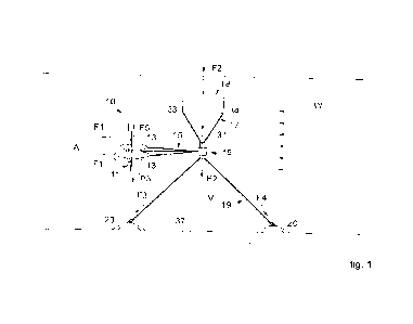
With reference to the attached drawings and in particular to fig. 1 and fig. 2
thereof, an apparatus 10 for producing electrical energy from water currents
comprises a converter device 11 configured to convert the kinetic energy of a
water
current into electrical energy, and provided with a first float 12 on the
sides of
which there is positioned a plurality of casings 13 equipped with turbines 14,
which
are configured to rotate under the effect of the water current and which are
each
connected to an electric generator 42 housed in a corresponding casing of the
plurality of casings 13.
The converter device 11 is connected by means of first connection elements 15
to an alignment device 16 connected on one side and by means of second
connection elements 17 to a second float 18, and on the other side and by
means
of third connection elements 19 to anchoring means 20. The alignment device 16
is configured to allow the turbines 14 to automatically align with the
direction W
of the water current.
CA 03231894 2024-3- 14
- 5 -
The first float 12 can be equipped with a first horizontal tail plane 39 and a
second vertical tail plane 40, which allow to increase the stability of the
converter
device 11 and to maintain its correct direction. The tail planes 39 and 40 are
positioned at the end of the first float 12 which is opposite to that of
connection to
the first connection elements 15.
In particular, the vertical tail plane 40 helps to achieve the alignment of
the
turbines 14 with the direction W of the water current.
The alignment device 16, see fig. 3, comprises an external ring 25 rotating
with
respect to a fixed internal pin 26. The first connection elements 15 are
connected
to the external ring 25, while the second and third connection elements 17 and
19
are connected to the internal pin 26. In particular, the second and third
connection
elements 17 and 19 are respectively connected to opposite ends 29 and 30 of
the
pin 26.
Between the pin 26 and the ring 25 there are positioned rolling means 27, for
example cylindrical rollers, spheres, or suchlike. The ring 25 centrally
comprises
a through hole 28 which the internal pin 26 passes through. The pin 26 and the
through hole 28 have a cylindrical shape. Preferably, the pin 26 has a greater
extension than the ring 25, so as to allow a better attachment of the second
and
third connection elements 17 and 19.
The turbines 14 can provide a plurality of blades 21 which are made to rotate
by
the sea current directed in the direction W so that, substantially, the axes
of rotation
A of the blades 21 automatically align with the direction W of the water
current,
in particular thanks to the presence of the vertical tail plane 40. The water
current
can be, for example, a marine water current, which possibly changes direction
of
origin cyclically, or for example a tidal current, but it is not excluded that
the
present apparatus can be used in lakes, rivers or other environments where a
water
current is present.
The first connection elements 15 comprise a cable 22 for connecting the first
float 12 to the external ring 25 of the alignment device 16.
The first connection elements 15 also comprise a rod 23 for connecting each of
the casings 13 to the device 16, wherein the rod 23 comprises at the
respective ends
a hinge 24 for rotation and possible release.
The second connection elements 17 can comprise a plurality of ropes 31
CA 03231894 2024-3- 14
- 6 -
attached on one side to the pin 26, for example by means of corresponding
couplings 32 positioned on the end 29, and on the other side to the second
float 18.
In particular, it is possible to provide a pair of ropes 31 attached to each
of the ends
33 and 34 of the second float 18, as in figs. 1 and 3.
Figs. 5, 6 and 7 show, purely by way of example, three advantageous
embodiments of the second float 18, 18', 18". The float 18 of fig. 5 has a
substantially cylindrical shape, the float 18' of fig. 6 has a toroidal shape,
while
the float 18" of fig. 7 has a rectangular parallelepiped shape. The shapes of
the
second float 18, 18', 18" are aimed at reducing resistance and maximizing
buoyancy, while guaranteeing the static stability and independence of the
float with
respect to the direction W of the current. However, the second float 18, 18',
18"
can also have different shapes than those shown.
The third connection elements 19 can comprise a plurality of ropes 35 attached
on one side to the pin 26, in particular to the end 30, and on the other side
to the
anchoring means 20 which, for example, can be placed on a seabed 37.
The instrumentation provided for the operation of the apparatus 10 can be
positioned inside the first float 12, for example instrumentation for data
acquisition
and control, electrical connections, back-up batteries, inertial platforms,
data
recorders or other. The first float 12 can be equipped with a watertight
access door
38.
The first float 12 can also contain chambers for the accumulation and
expulsion
of air in order to ensure the right buoyancy and configuration, both managed
through the expulsion, inlet or transfer of air and water between the various
chambers.
The converter device 11 can also be equipped with a bulb 41, positioned
underneath the first float 12, which is ballasted and allows to increase the
stability
of the converter device 11 and therefore of the apparatus 10.
The casings 13 are watertight and the electric generator 42 housed inside them
can be connected to a revolutions multiplier, in turn connected to the rotor
of the
turbine 14.
The casings 13 can be connected to the first float by means of structures
which
can have sections or a fairing similar in shape to wing profiles 36, which
contribute
to increasing the stability and improving the hydrodynamic behavior of the
CA 03231894 2024-3- 14
- 7 -
apparatus 10. The casings 13 and the first float 12 can be reciprocally
connected
so that they are substantially coplanar.
The turbines 14 are made to rotate by the sea current and transmit the
mechanical torque thus generated to the electric generators 42, thus allowing
to
transform the kinetic energy first into mechanical rotation energy and then
into
electrical energy.
The alignment device 16 substantially allows the 360' rotation of the
converter
device 11, so that it can align with the direction W of the water current,
acting as
a sort of bearing which, thanks to the rotation of the external ring 25 with
respect
to the internal pin 26, allows the automatic alignment of the converter device
11
with the direction W of the sea current. The ring 25 can rotate with respect
to the
pin 26 about an axis V which is substantially orthogonal to the direction W of
the
sea current.
When the apparatus 10 is in operation, advantageously, the first float 12 is
discharged by the thrust forces Fl acting on the turbines 14, which are
transmitted
directly through the first connection elements 15, in particular the traction-
loaded
rods 23, to the internal pin 26 of the alignment device 16, which is suitably
sized.
The buoyancy force F2 of the second float 18 and the reactions F3 and F4 of
the
anchoring means 20 are in equilibrium with each other thanks to the internal
pin
26 which absorbs these loads and which passes through the alignment device 16.
Fig. 1 also shows the weight forces P1, P2 and P3 of the second float 18, of
the
alignment device 16 and of the converter device 11, respectively, and also the
buoyancy force F5 of the first float 12.
The sole function of first float 12 of the converter device 1 l is therefore
substantially to house the instrumentation and to maintain a neutral or
slightly
positive buoyancy of the converter device 11.
During its operation, the equilibrium of the converter device 11 which is
submerged at the desired depth is ensured by the equilibrium of the traction
of the
mooring of the anchoring means 20, by the thrust of the sea current in the
direction
W which is generated on the blades 21 of the turbines 14, and by the buoyancy
force F5 of the first float 12.
The converter device 11 can be connected to the electric network by means of
an electric cable for example, which runs along one of the mooring ropes 35
and
CA 03231894 2024-3- 14
- 8 -
extends to an electric cabin or to batteries installed on shore.
During operation, the converter device 11 behaves like a sort of submarine
kite
that remains fixed in position thanks to the equilibrium of the forces Fl -F5,
of the
weights P -P3 and of the sea current acting in the direction W.
The anchoring means 20 can be of a dead weight type, with installation by
means of foundation piles in the seabed or with any known anchoring technique
whatsoever.
For sites where the intention is to exploit tidal currents with a well-known
current direction, it is possible to provide that the converter device 11
varies its
direction by about 180 when the direction of the tide changes, therefore for
rising
and dropping tidal currents. For example, please see fig. 4: the sea current
initially
directed in the direction W1 slowly changes direction, by about 180 , until it
is
directed in the direction W2. The converter device 11, thanks to the device 16
and
to the vertical tail plane 40, realigns itself, positioning itself at the
opposite end.
To prevent the electric cable from twisting, the converter device 11 can be
allowed to always rotate in the same direction, thus occupying a space
relative to
an arc of 180 . If the system, upon a change of direction of the current,
wants to
rotate in the wrong direction, one or both turbines 14 are briefly driven,
thus
functioning as propellers, and through their control they pre-align the
converter
device 11 in the correct direction of rotation. The presence of the vertical
tail plane
40 will allow to complete the step of rotation in the correct direction in a
passive
manner.
The present apparatus 10 advantageously offers the possibility of automatic
and
passive rotation of the entire converter device 11, thus allowing its
"natural"
alignment with the sea current, without needing the continuous action of
active
control systems for the alignment. The need to align the axis A of the rotor
of the
turbines 14 with the current derives from the fact that in this condition the
efficiency of the turbines is maximum compared to those cases in which the
current
hits the rotor with an angle with respect to the axis of the rotor itself
different to
zero.
Another advantage of the present apparatus 10 lies in the possibility of
surfacing
the converter device 11, for example by releasing the connection of the rods
23 in
the hinges 24, releasing the cable 22 by means of a winch positioned in the
first
CA 03231894 2024-3- 14
- 9 -
float 12 and by filling the internal watertight chambers with air taken from
the
internal tanks, which increases the overall buoyancy of the system allowing it
to
climb. The surfacing can be useful for carrying out routine maintenance of the
electric generators 42, the turbines 14, or other. The possibility of carrying
out
maintenance of the most delicate components of the system out of the water
through a simple surfacing operation is an important feature in completely
submerged systems that generate energy from sea currents. The systems that are
positioned on the seabed by means of a structure or tower require maintenance
that
is either carried out at the installation depth, or for which ships arc
required that
have to bring the entire structure out of the water, both operations that are
extremely costly from an economic point of view. The positioning of the
present
apparatus 10 at an intermediate depth between the free surface of the water
and the
seabed 37, as shown in fig. 1, has multiple advantages: the possibility of
intercepting the maximum speed of the sea current, therefore the speed that
allows
a greater production of energy by the turbines 14; the sea current, in fact,
is
significantly reduced when moving from the surface of the sea toward the
seabed.
The absence of interaction of the system, during its operation, with wave
motion,
the effects of which are greatest in proximity to the free surface of the
water, for
example during extreme events. Furthermore, for some systems with structures
always floating above sea level, the weather and maritime traffic represent a
problem for correct operation. The total absence of visual impact.
It is clear that modifications and/or additions of parts or steps may be made
to
the apparatus 10 for producing electrical energy from water currents as
described
heretofore, without departing from the field and scope of the present
invention, as
defined by the claims.
In the following claims, the sole purpose of the references in brackets is to
facilitate reading and they must not be considered as restrictive factors with
regard
to the field of protection claimed in the specific claims.
CA 03231894 2024-3- 14