Note: Descriptions are shown in the official language in which they were submitted.
CA 03232408 2024-03-12
WO 2023/086086 PCT/US2021/058830
DEBRIS RESISTANT KEYED RUNNING TOOL AND METHOD
CROSS-REFERENCE TO RELATED APPLICATION
[0001] This application claims priority to U.S. Application Serial No.
17/523,533, filed on
November 10, 2021, entitled "DEBRIS RESISTANT KEYED RUNNING TOOL AND
METHOD," commonly assigned with this application and incorporated herein by
reference in its
entirety.
BACKGROUND
[0002] A variety of borehole operations require selective access to specific
areas of the wellbore.
One such selective borehole operation is horizontal multistage hydraulic
stimulation, as well as
multistage hydraulic fracturing ("frac" or "fracking"). In multilateral wells,
the multistage
stimulation treatments are performed inside multiple lateral wellbores.
Efficient access to all
lateral wellbores is critical to complete a successful pressure stimulation
treatment, as well as is
critical to selectively enter the multiple lateral wellbores with other
downhole devices.
BRIEF DESCRIPTION
[0003] Reference is now made to the following descriptions taken in
conjunction with the
accompanying drawings, in which:
[0004] FIG. 1 illustrates a well system designed, manufactured, and operated
according to one or
more embodiments of the disclosure;
[0005] FIG. 2 illustrates one embodiment of a multilateral junction designed,
manufactured
and/or operated according to one or more embodiments of the disclosure;
[0006] FIGs. 3A through 3H illustrate various different views of a slotted
orientation apparatus
designed, manufactured, and operated according to one or more embodiments of
the disclosure;
[0007] FIG. 31 illustrates an example of employing the angle of repose of a
material in the
tubular to calculate the angle X;
[0008] FIGs. 4A through 4D illustrate various different views of a slotted
orientation apparatus
designed, manufactured, and operated according to one or more alternative
embodiments of the
disclosure;
[0009] FIGs. 5A through 5D illustrate different views of a keyed running tool
designed,
manufactured and operated according to one or more embodiments of the
disclosure; and
-1-
CA 03232408 2024-03-12
WO 2023/086086 PCT/US2021/058830
[0010] FIGs. 6A through 6F illustrate one embodiment for aligning a downhole
tool in
accordance with the disclosure.
DETAILED DESCRIPTION
[0011] In the drawings and descriptions that follow, like parts are typically
marked throughout
the specification and drawings with the same reference numerals, respectively.
The drawn
figures are not necessarily to scale. Certain features of the disclosure may
be shown exaggerated
in scale or in somewhat schematic form and some details of certain elements
may not be shown
in the interest of clarity and conciseness. The present disclosure may be
implemented in
embodiments of different forms.
[0012] Specific embodiments are described in detail and are shown in the
drawings, with the
understanding that the present disclosure is to be considered an
exemplification of the principles
of the disclosure, and is not intended to limit the disclosure to that
illustrated and described
herein. It is to be fully recognized that the different teachings of the
embodiments discussed
herein may be employed separately or in any suitable combination to produce
desired results.
[0013] Unless otherwise specified, use of the terms "connect," "engage,"
"couple," "attach," or
any other like term describing an interaction between elements is not meant to
limit the
interaction to direct interaction between the elements and may also include an
indirect interaction
between the elements described.
[0014] Unless otherwise specified, use of the terms "up," "upper," "upward,"
"uphole,"
"upstream," or other like terms shall be construed as generally away from the
bottom, terminal
end of a well, regardless of the wellbore orientation; likewise, use of the
terms "down," "lower,"
"downward," "downhole," or other like terms shall be construed as generally
toward the bottom,
terminal end of a well, regardless of the wellbore orientation. Use of any one
or more of the
foregoing terms shall not be construed as denoting positions along a perfectly
vertical axis.
Unless otherwise specified, use of the term "subterranean formation" shall be
construed as
encompassing both areas below exposed earth and areas below earth covered by
water such as
ocean or fresh water.
[0015] The present disclosure acknowledges that there are certain instances,
particularly during
stimulation and/or fracturing operations, where it may be desirable to employ
a slotted
orientation apparatus (e.g., also known in the art as a slotted muleshoe) to
position a downhole
tool within a wellbore. The present disclosure, based upon this
acknowledgment, has recognized
-2-
CA 03232408 2024-03-12
WO 2023/086086 PCT/US2021/058830
that debris, such as frac sand in one embodiment, may collect within the slot
in the slotted
orientation apparatus and present problems with a key of an associated keyed
running tool
sliding within the slot. With this in mind, the present disclosure has in one
embodiment designed
a slotted orientation apparatus with the placement of the slot on a high side
of the tubular (e.g.,
such that no portion of the slot is located below 3 o'clock or below 9 o'clock
relative to gravity),
which greatly reduces this problem. For example, such an embodiment could
employ a slot that
radially extends around the tubular 180 degrees or less, and in one embodiment
a slot that has its
radial centerpoint positioned at 12 o'clock relative to gravity. In accordance
with at least one
embodiment, an orientation tool could be coupled to the slotted orientation
apparatus, the
orientation tool configured to orient the slot of the slotted orientation
apparatus within the
wellbore (e.g., on the high side of the tubular). In yet another embodiment
the orientation tool is
a measurement while drilling (MWD) tool that uses pressure pulses to orient
the slot of the
slotted orientation apparatus within the wellbore.
[0016] The present disclosure has additionally acknowledged that it can, at
times, be difficult to
align the keys of the keyed running tool with the slot in the slotted
orientation apparatus. The
present disclosure has recognized that such can especially be the case when
the slot in the slotted
orientation apparatus does not extend entirely around the tubular, such as is
the case with the
aforementioned slotted orientation apparatus with the placement of the slot on
the high side of
the tubular. With this acknowledgment in mind, the present disclosure designed
a keyed running
tool having two or more keys movable between a radially retracted state and a
radially extended
state, wherein adjacent ones of the two or more keys are laterally offset from
each other and
radially offset from each other by Y degrees, wherein Y is 180 degrees or
less. Given this
design, ideally at least one of the two keys would engage with the slot when
the keyed running
tool is being deployed downhole.
[0017] FIG. 1 illustrates a well system 100 designed, manufactured, and
operated according to
one or more embodiments of the disclosure. The well system 100 includes a
platform 120
positioned over a subterranean formation 110 located below the earth's surface
115. The
platform 120, in at least one embodiment, has a hoisting apparatus 125 and a
derrick 130 for
raising and lowering a downhole conveyance 140, such as a drill string, casing
string, tubing
string, coiled tubing, a running tool, etc. Although a land-based oil and gas
platform 120 is
illustrated in FIG. 1, the scope of this disclosure is not thereby limited,
and thus could potentially
-3-
CA 03232408 2024-03-12
WO 2023/086086 PCT/US2021/058830
apply to offshore applications. The teachings of this disclosure may also be
applied to other land-
based multilateral wells different from that illustrated.
[0018] The well system 100, in one or more embodiments, further includes a
main wellbore
150. The main wellbore 150, in the illustrated embodiment, includes tubing
160, 165, which
may have differing tubular diameters. Extending from the main wellbore 150, in
one or more
embodiments, may be one or more lateral wellbores 170. Furthermore, a
plurality of multilateral
junctions 175 may be positioned at junctions between the main wellbore 150 and
the lateral
wellbores 170. The multilateral junctions 175 may be designed, manufactured
and operated
according to one or more embodiments of the disclosure. In accordance with at
least one
embodiment, the multilateral junction 175 may include a slotted orientation
apparatus and/or
keyed running tool according to any of the embodiments, aspects, applications,
variations,
designs, etc. disclosed in the following paragraphs.
[0019] The well system 100 may additionally include one or more ICVs 180
positioned at
various locations within the main wellbore 150 and/or one or more of the
lateral wellbores 170.
The well system 100 may additionally include a control unit 190. The control
unit 190, in this
embodiment, is operable to provide control to or received signals from, one or
more downhole
devices.
[0020] Turning to FIG. 2, illustrated is one embodiment of a multilateral
junction 200 designed,
manufactured and/or operated according to one or more embodiments of the
disclosure. The
multilateral junction 200, in the illustrated embodiment, includes a slotted
orientation apparatus
210. In at least one embodiment, the slotted orientation apparatus 210
includes a tubular having
a wall thickness (t). The slotted orientation apparatus 210, in at least one
other embodiment,
additionally includes a slot extending at least partially through the tubular,
the slot having first
and second axial portions laterally offset from one another by a distance
(ds), and an angled
portion connecting the first and second axial portions, wherein the slot
radially extends around
the tubular X degrees, wherein X is 180 degrees or less. In one or more
embodiments, the slot
extends entirely through the wall thickness (t) of the slotted orientation
apparatus 210, but in
other embodiments the slot only extends into an inner surface of the slotted
orientation apparatus
210 (e.g., only partially through the wall).
[0021] The multilateral junction 200, in the illustrated embodiment,
additionally includes a
tubular spacer 220 positioned downhole of the slotted orientation apparatus
210, a whipstock 230
-4-
CA 03232408 2024-03-12
WO 2023/086086 PCT/US2021/058830
positioned downhole of the tubular spacer 220, and a y-block 240 positioned
downhole of the
whipstock 230. In the embodiment of FIG. 2, the multilateral junction 200
additionally includes
a main bore leg 250 and a lateral bore leg 260 coupled to a downhole end of
the y-block.
[0022] A keyed running tool (not shown) could be used to position (e.g.,
rotationally position)
one or more features within the multilateral junction 200. For example, the
key(s) of the keyed
running tool could slide within the slot of the slotted orientation apparatus
210 to position the
one or more features within the multilateral junction 200. In at least one
embodiment, the keyed
running tool is configured to position the whipstock 240 (e.g., a tubing exit
whipstock "TEW") at
a desired lateral and rotational position within the multilateral junction
200. Notwithstanding the
foregoing, the slotted orientation apparatus 210 could be used to positioned
different features
within the multilateral junction 200, or alternatively could be used to
positioned different
features not associated with the multilateral junction 200.
[0023] Turning to FIGs. 3A through 3H, illustrated are various different views
of a slotted
orientation apparatus 300 designed, manufactured, and operated according to
one or more
embodiments of the disclosure. FIG. 3A illustrates a top-down view of the
slotted orientation
apparatus 300, whereas FIGs. 3B through 3D illustrate various different
sectional views of the
slotted orientation apparatus 300 taken through the top-down view of FIG. 3A.
In contrast, FIG.
3E illustrates a right-side view of the slotted orientation apparatus 300,
whereas FIGs. 3F
through 3H illustrate various different sectional views of the slotted
orientation apparatus 300
taken through the right-side view of FIG. 3E. Each of the views illustrated in
FIGs. 3A through
3H additionally illustrate clock settings, as would relate to the illustrated
point of gravity. The
slotted orientation apparatus 300, in at least one embodiment, is configured
for use with a keyed
running tool, such as that discussed below, and may be positioned within
another tubular, such as
casing.
[0024] The slotted orientation apparatus 300, in the embodiment illustrated in
FIGs. 3A through
3H, includes a tubular 310 having a wall thickness (t). Many different tubular
materials, and
wall thicknesses (t), may be used for the tubular 310 and remain within the
scope of the
disclosure. Nevertheless, in at least one embodiment, the tubular 310 is a
steel tubular, and the
wall thickness (t) ranges from .07 cm to 5 cm. Furthermore, in at least one
embodiment, the
tubular could have a length (1) ranging from 5 cm to 18.5 m.
-5-
CA 03232408 2024-03-12
WO 2023/086086 PCT/US2021/058830
[0025] In accordance with at least one other embodiment of the disclosure, the
slotted orientation
apparatus 300 includes a slot 320 extending through the tubular 310. In one or
more
embodiments, the slot 320 has first and second axial portions 330, 340
laterally offset from one
another by a distance (ds), and an angled portion 335 connecting the first and
second axial
portions 330. 340. The slot 320, in at least one embodiment, radially extends
around the tubular
310 by X degrees, wherein X is 180 degrees or less. In at least one other
embodiment, X is less
than 180 degrees. In yet another embodiment, such as shown in FIGs. 3A through
3H, X is 120
degrees or less, and in one embodiment 120 degrees. In even yet another
embodiment, X is 90
degrees or less. As will be discussed in greater detail below, the actual
degrees for X may relate
to the number of keys employed in the keyed running tool. For example, if
three equally spaced
keys are used, X would equal 120 degrees. If four equally spaced keys were
used, X would
equal 90 degrees. If five equally spaced keys were used, X would equal 72
degrees.
[0026] The angle X may also be based upon the coefficient of friction between
the material
within the tubular 310 (e.g., frac sand, coated frac proppant, formation
fines, etc.) and the angled
surfaces of the slot 320, as well as the angle of repose of the material
within the tubular 310. For
example, in at least one embodiment, frac sand is being deployed down the
tubular 310.
Accordingly, the frac sand might have an angle of repose of Z degrees (e.g.,
wet sand has an
angle of repose of 45 degrees), and the angle X might be chosen based upon the
aforementioned
coefficient of friction and the angle of repose of Z degrees (e.g., say for
example 45 degrees).
Thus, the combination of the coefficient of friction between the frac sand and
the lower ledge of
the slot 320, along with the angle of repose of Z degrees, would cause the
frac sand to not collect
on the angled surfaces of the slot 320.
[0027] As an example, the angle X might be less than twice a complementary
angle of repose of
the material within the tubular 310 (e.g., X < 2* (90 - angle of repose of
material, or ()Rep)) when
a radial centerpoint of the slot 320 is positioned at 12 o'clock relative to
gravity, as shown in
FIG. 31. In one embodiment, the material might have an angle of repose (ORep)
of at least 15
degrees (e.g., water filled sand), and the angle X would be less than 150
degrees (e.g., X < 2*
(90 - 15 )). In another embodiment, the material might have an angle of
repose (ORep) of at least
30 degrees (e.g., water filled sand), and the angle X would be less than 120
degrees (e.g., X < 2*
(90 - 30 )). In yet another embodiment, the material might have an angle of
repose (ORep) of at
least 40 degrees, and the angle X would be less than 100 degrees (e.g., X < 2*
(90 - 40 )). In yet
-6-
CA 03232408 2024-03-12
WO 2023/086086 PCT/US2021/058830
another embodiment, the material might have an angle of repose (ORep) of at
least 45 degrees, and
the angle X would be less than 90 degrees (e.g., X <2* (900 - 45 )).
[0028] The slot 320, in certain embodiments, is located on a high side of the
tubular 310 such
that no portion of the slot 320 is located below 3 o'clock or below 9 o'clock
relative to gravity.
In such embodiments, X would need to be less than 180 degrees to accommodate a
width of the
first and second axial portions 330, 340. For example, depending on the width
of the first and
second axial portions 330, 340, X might need to be 175 degrees or less to
accommodate the
aforementioned high side. In certain other embodiments, such as that shown in
FIGs. 3A
through 3H, a radial centerpoint of the slot 320 is positioned at 12 o'clock
relative to gravity.
[0029] Further to the embodiment of FIGs. 3A through 3H, the slot 320 may have
a length (ls),
and the first and second axial portions may have a length (lap). Thus, in
accordance with one or
more embodiments, the length (lb) ranges from 2.5 cm to 900 cm and the length
(lap) ranges from
1 cm to 600 cm. Similarly, in an embodiment, the distance (ds) ranges from 1
cm to 900 cm,
among others. Given certain dimensions of the slot 320, an angle (0) of the
angled portion 335
may range from 15 degrees to 60 degrees, and in yet another embodiment from 25
degrees to 50
degrees.
[0030] Turning to FIGs. 4A through 4D, illustrated are various different views
of a slotted
orientation apparatus 400 designed, manufactured, and operated according to
one or more
alternative embodiments of the disclosure. FIG. 4A illustrates a top-down view
of the slotted
orientation apparatus 400, whereas FIGs. 4B through 4D illustrate various
different sectional
views of the slotted orientation apparatus 400 taken through the top-down view
of FIG. 4A. The
slotted orientation apparatus 400 is similar in many respects to the slotted
orientation apparatus
300. Accordingly, like reference numbers have been used to indicate similar,
if not identical,
features. For example, the slotted orientation apparatus 400 includes the
first axial portion 330,
the angled portion 335, and the second axial portion 340. Nevertheless, the
slotted orientation
apparatus 400 employs an open-type slot 420, as opposed to the more closed-
type slot 320 of the
slotted orientation apparatus 300.
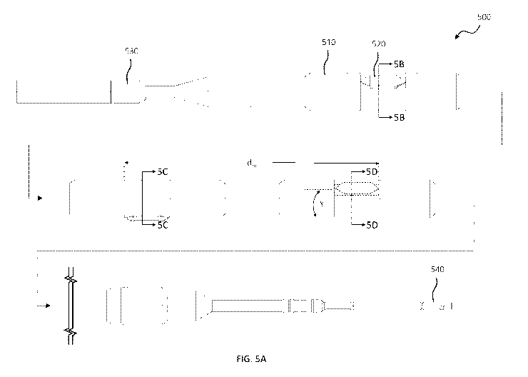
[0031] Turning to FIGs. 5A through 5D, illustrated are different views of a
keyed running tool
500 designed, manufactured and operated according to one or more embodiments
of the
disclosure. FIG. 5A illustrates an isometric view of the keyed running tool
500, whereas FIGs.
5B through 5D illustrated cross-sectional views taken at various different
locations of the keyed
-7-
CA 03232408 2024-03-12
WO 2023/086086 PCT/US2021/058830
running tool 500. The keyed running tool 500, in at least one embodiment, is
configured for use
with a slotted orientation apparatus, such as the slotted orientation
apparatus 300 illustrated
above with regard to FIGs. 3A through 4D.
[0032] The keyed running tool 500 illustrated in FIGs. 5A through 5D, in one
or more
embodiments, includes a housing 510. The housing 510 may comprise many
different shapes,
lengths and/or materials while remaining within the scope of the disclosure.
In at least one
embodiment, however, the housing 510 comprises steel. Housing 510 may comprise
more than
one component in order to perform its function (securing the more than one
key, alignment of the
keys, attaching the main housing to tools at one or both ends.
[0033] The keyed running tool 500, in accordance with one embodiment of the
disclosure,
includes two or more keys 520 extending from the housing 510. The two or more
keys 520, in
certain embodiments, are movable between a radially retracted state (e.g.,
where they may be
flush with an outside diameter of the housing 510) and a radially extended
state (e.g., such as
shown, where they extend beyond the outside diameter of the housing 510). For
example, the
two or more keys 520 may be two or more spring loaded keys 520, and remain
within the scope
of the disclosure. In the embodiment of FIGs. 5A through 5D, the keyed running
tool 500
includes three keys 520.
[0034] In accordance with one embodiment of the disclosure, adjacent ones of
the two or more
keys 520 are radially offset from each other by Y degrees, wherein Y is 180
degrees or less. For
example, depending on the number of keys 520, Y may vary. For example, if
three equally
spaced keys are used, Y would equal 120 degrees. If four equally spaced keys
were used, Y
would equal 90 degrees. If five equally spaced keys were used, Y would equal
72 degrees. In
certain instances, it may be advantageous to have an odd number of equally
spaced keys, such
that no two keys are radially offset from one another by 180 degrees. In
certain instances, it may
be advantageous to have the three-or-more keys spaced at different angles from
one another. For
example, if the assembly that needs to be urged into a certain orientation,
but its center of mass is
not positioned along the centerline, then having two keys engaged at a
particular orientation can
distribute the stresses over a larger area to reduce the stresses upon the
keys (and slots).
Likewise, the keys may be made wider to increase the load-bearing area of the
keys to reduce the
stresses upon the keys and orientation slot.
-8-
CA 03232408 2024-03-12
WO 2023/086086 PCT/US2021/058830
[0035] In accordance with one embodiment of the disclosure, adjacent ones of
the two or more
keys 520 are laterally offset from each other. For example, adjacent ones of
the two or more
keys are laterally offset from each other by a maximum distance (dm). In at
least one
embodiment, the maximum distance (dm) ranges from 2.5 cm to 900 cm.
Nevertheless, other
values for the maximum distance (dm) are within the scope of the disclosure.
[0036] In certain embodiments, the value for the Y (e.g., the radial offset of
the keys 520) and
the value for X (e.g., how far the slot of the slotted orientation apparatus
radially extends around
the tubular) relate to one another. For example, certain embodiments exist
wherein the value for
Y is substantially equal to the value for X. The term "substantially equal,"
as used herein with
respect to the associated values for Y and X, means that the values are within
10 percent of one
another, for example to accommodate a width of the key 520. In other
embodiments, the value
for Y is ideally equal to the value for X. The term "ideally equal," as used
herein with respect to
the associated values for Y and X, means that the values are within 5 percent
of one another, for
example to accommodate a width of the key 520. In yet other embodiments, the
value for Y is
exactly equal to the value for X. The term "exactly equal," as used herein
with respect to the
associated values for Y and X, means that the values are within 1 percent of
one another.
[0037] Similarly, in certain embodiments, the maximum distance (dm) (e.g., the
maximum lateral
offset of adjacent key 520) and the length (lb) of the slot of the slotted
orientation apparatus relate
to one another. For example, in certain embodiments it is beneficial for two
or more of the keys
520 to reside within the slot at the same time. Accordingly, in at least one
embodiment, the
maximum distance (dm) is less than the length (ls). However, in certain other
embodiments it is
beneficial for the two or more keys 520 to reside within the first and second
axial portions of the
slot, respectively, thus the maximum distance (dm) is greater than the
distance (ds) (e.g., the
lateral distance between the first and second axial portions).
[0038] The keyed running tool 500, in one or more embodiments, may
additionally include a
swivel 530 coupled to an uphole end of the housing 510. In at least one
embodiment, the swivel
530 is configured to allow the housing 510 and the two or more keys 520 to
rotate when
following a slot in a slotted orientation apparatus. The keyed running tool
500 may additionally
include an engagement member 540 coupled to a downhole end of the housing 510.
The
engagement member 540, in at least on embodiment, is configured to engage with
a downhole
tool and rotationally position the downhole tool within a wellbore it is
located within. For
-9-
CA 03232408 2024-03-12
WO 2023/086086 PCT/US2021/058830
example, the engagement member 540 could engage with a whipstock, such as the
whipstock
230 illustrated in FIG. 2, in which case the keyed running tool 500 would be
used to rotationally
position the whipstock 230 within the multilateral junction 200.
[0039] Turning now to FIGs. 6A through 6F, illustrated is one embodiment for
aligning a
downhole tool in accordance with the disclosure. For example, the embodiment
for aligning a
downhole tool could include employing a slotted orientation apparatus 600 and
a keyed running
tool 650 for aligning a downhole tool. In at least one embodiment, the slotted
orientation
apparatus 600 and the keyed running tool 650 are similar to the slotted
orientation apparatus 300
and the keyed running tool 500 discussed above. Thus, in at least one
embodiment, the slotted
orientation apparatus 600 could include a tubular 610, as well as a slot 620
extending through the
tubular, the slot having first and second axial portions 630, 640 laterally
offset from one another
by a distance (ds), and an angled portion 635 connecting the first and second
axial portions 630,
640. In accordance with at least one embodiment, the slot 620 radially extends
around the
tubular 610 X degrees, wherein X is 180 degrees or less. Similarly, in at
least one embodiment,
the keyed running tool 650 could include a housing 660, as well as two or more
keys 670
extending from the housing 660, the two or more keys 670 movable between a
radially retracted
state and a radially extended state. In accordance with at least one
embodiment, adjacent ones of
the two or more keys 670 are laterally offset from each other and radially
offset from each other
by Y degrees, wherein Y is 180 degrees or less.
[0040] In the embodiment of FIGs. 6A through 6F, the slot 620 of the slotted
orientation
apparatus 600 radially extends around the tubular 610 by 120 degrees.
Similarly, the keyed
running tool 650 includes three keys, including a downhole key 670a, a middle
key 670b, and an
uphole key 670c. Further to the embodiment of FIGs. 6A through 6F, the
downhole key 670a,
middle key 670b, and uphole key 670c are radially offset from each other by
120 degrees. While
a three key 670 and 120 degree design is being illustrated and described with
regard to FIGs. 6A
through 6F, other number of keys 670 and radial spacing are within the scope
of the disclosure.
[0041] With reference to FIG. 6A, the keyed running tool 650 is initially at
least partially
engaged with the slotted orientation apparatus 600. For example, in the
embodiment of FIG. 6A,
the downhole key 670a is laterally aligned with the slot 620 when the keyed
running tool 650 is
being pushed downhole. Thus, in the embodiment of FIG. 6A, the downhole key
670a may
engage with the slot 620, as is shown. While FIG. 6A illustrates the downhole
key 670a
-10-
CA 03232408 2024-03-12
WO 2023/086086 PCT/US2021/058830
positioned in the angled portion 635 of the slot 620, depending on the initial
radial alignment
between the downhole key 670a and the slot 620, the downhole key 670a might
alternatively
initially engage the first axial portion 630 or initially engage the second
axial portion 640.
Additionally, as the keys 670 are movable between radially retracted states
and radially extended
states, a location at which the keys 670 engage with the slot 620 has no
effect on the keys 670.
[0042] With reference to FIG. 6B, illustrated is the keyed running tool 650 of
FIG. 6A after
continuing to push the keyed running tool 650 downhole causing the downhole
key 670a to
rotate within the slot 620 until the downhole key 670a is positioned within
the second axial
portion 640 of the slot 620 and the middle key 670b is positioned within the
first axial portion
630 of the slot 620. As the maximum distance (dm) between the downhole key
670a and the
middle key 670b is less than the length (1s) of the slot 620, both of the
downhole key 670a and
the middle key 670b may be simultaneously located within the slot 620.
Moreover, in certain
embodiments, the relationship between the maximum distance (dm) and the length
(1s) dictates
that no more than two keys 670 may be engaged with the slot 620 at any one
given moment in
time. Furthermore, as the radial value for X is substantially similar to the
radial value for Y, the
downhole key 670a and the middle key 670b may be simultaneously located within
second axial
portion 640 and the first axial portion 630, respectively.
[0043] With reference to FIG. 6C, illustrated is the keyed running tool 650 of
FIG. 6B after
continuing to push the keyed running tool 650 downhole causing the downhole
key 670a to
move to its radially retracted state (e.g., within the tubular 610) and the
middle key 670b to rotate
to the angled portion 635 of the slot 620. Given the spacing between adjacent
keys 670, in one
or more embodiments, if one key (e.g., the middle key 670b) is located within
the angled portion
635 of the slot 620, an adjacent key 670 (e.g., the downhole key 670a or the
uphole key 670c)
cannot also be located within the slot 620.
[0044] With reference to FIG. 6D, illustrated is the keyed running tool 650 of
FIG. 6C after
continuing to push the keyed running tool 650 downhole causing the middle key
670b to rotate
within the slot 620 until the middle key 670b is positioned within the second
axial portion 640 of
the slot 620 and the uphole key 670c is positioned within the first axial
portion 630 of the slot
620. As the maximum distance (dm) between the middle key 670b and the uphole
key 670c is
less than the length (1s) of the slot 620, both of the middle key 670b and the
uphole key 670c may
be simultaneously located within the slot 620. Furthermore, as the radial
value for X is
-11-
CA 03232408 2024-03-12
WO 2023/086086 PCT/US2021/058830
substantially similar to the radial value for Y, the middle key 670b and the
uphole key 670c may
be simultaneously located within second axial portion 640 and the first axial
portion 630,
respectively.
[0045] With reference to FIG. 6E, illustrated is the keyed running tool 650 of
FIG. 6D after
continuing to push the keyed running tool 650 downhole causing the middle key
670b to also
move to its radially retracted state (e.g., within the tubular 610) and the
uphole key 670c to rotate
to the angled portion 635 of the slot 620. Given the spacing between adjacent
keys 670, in one
or more embodiments, if one key (e.g., the uphole key 670c) is located within
the angled portion
635 of the slot 620, adjacent key 670 (e.g., the downhole key 670a or the
middle key 670b)
cannot also be located within the slot 620.
[0046] With reference to FIG. 6F, illustrated is the keyed running tool 650 of
FIG. 6E after
continuing to push the keyed running tool 650 downhole causing the uphole key
670c to rotate
within the slot 620 until the uphole key 670c is positioned within the second
axial portion 640 of
the slot 620. At this stage, at least in the embodiment of FIGs. 6A through
6F, the keyed running
tool 650 bottoms out, and thus cannot move any further downhole. Moreover, in
certain
embodiments, any downhole tool coupled to the keyed running tool 650 is
rotationally, and
laterally, placed at a desired position within the wellbore.
[0047] The embodiment of FIGs. 6A through 6F assume that the downhole key 670a
is initially
radially aligned with the slot 620 such that as the keyed running tool 650 is
pushed downhole the
downhole key 670a would engage with at least one of the first axial portion
630, the angled
portion 635, or the second axial portion 640. Nevertheless, in certain
instances the downhole key
670a would be radially misaligned with the slot 620 such that as the keyed
running tool 650 is
pushed downhole the downhole key 670a would not engage with the slot 620. In
such an
instance, either one of the middle key 670b or the uphole key 670c might
initially radially align
with the slot 620.
[0048] In the instance where the downhole key 670a is radially misaligned with
the slot 620 but
the middle key 670b is at least partially radially aligned with the slot 620,
the keyed running tool
650 would be pushed downhole causing the downhole key 670a to miss the slot
620 and the
middle key 670b to initially engage with and rotate within the slot 620 until
the middle key 670b
is positioned within the second axial portion 640 of the slot 620 and the
uphole key 670c is
positioned within the first axial portion 630 of the slot 620, very similar to
that shown in FIGs.
-12-
CA 03232408 2024-03-12
WO 2023/086086 PCT/US2021/058830
6C and 6D. Thereafter, the process would proceed by continuing to push the
keyed running tool
650 downhole causing the uphole key 670c to rotate within the slot 620 until
the uphole key
670c is positioned within the second axial portion 640, at which time the
downhole tool is
rotationally positioned within the wellbore, very similar to that shown in
FIGs. 6E and 6F.
[0049] In the instance where the downhole key 670a and the middle key 670b are
both radially
misaligned with the slot 620 but the uphole key 670c is at least partially
radially aligned with the
slot 620, the keyed running tool 650 would be pushed downhole causing the
downhole key 670a
and middle key 670b to miss the slot 620 and the uphole key 670c to initially
engage with and
rotate within the slot 620 until the uphole key 670c is positioned within the
second axial portion
640, at which time the downhole tool is rotationally positioned within the
wellbore, very similar
to that shown in FIGs. 6E and 6F.
[0050] Unique to at least one embodiment of the design, no matter the radial
alignment between
the keyed running tool 650 and the slotted orientation apparatus 600, at least
one of the
downhole key 670a, the middle key 670b, or the uphole key 670c will at least
partially align with
the slot 620. Accordingly, regardless of the radial alignment, in at least one
embodiment the
uphole key 670c will ultimately always end up in the second axial portion 640,
resulting in the
downhole tool that is coupled to a downhole end of the keyed running tool 650
being both
laterally and rotationally positioned as a desired located within the
wellbore.
[0051] It should be apparent to one skilled in the art that the keyed running
tool 650 may also
align with respect to the slotted orientation apparatus 600 when traveling
from below the slotted
orientation apparatus 600 in an upward motion (e.g., provided the keys 670a,
670b and 670c
have the proper profile to engage the slot 620 in the slotted orientation
apparatus 600. For
example, the keys 670a, 670b and 670c could engage with the slot 620 in the
opposite manner as
was described above with respect to FIGs. 6A through 6F.
[0052] It should also be noted that the slotted orientation apparatus 600 may
have an upward no-
go to hold the keyed running tool 650 in an axial position until a desired
amount of upward force
is exerted to cause the no-go mechanism (not shown) to allow further upwardly
movement. In
some embodiments, one or more of the keys (e.g., uphole key 670c) may provide
the desired
resistance to temporarily halt the upward movement of the keyed running tool
650 (e.g., until
additional force is applied).
-13-
CA 03232408 2024-03-12
WO 2023/086086 PCT/US2021/058830
[0053] It should also be noted that the slotted orientation apparatus 600 may
be designed to slide
/ fit inside a standard API-type casing, or a specially designed tubular with
an OD similar (or
different) than a standard API casing, tubing, or other tubular.
[0054] It should be noted that the lengths of the first and second axial
portions 630, 640 do not
have to be the same. In some examples it may be desirable for the keyed
running tool 650 to be
held at a certain orientation by one or more of the keys 670 until an
additional distance has been
traveled - or a certain event has occurred (e.g., mating up with another
assembly pre-installed in
the well).
[0055] It should be apparent that the slotted orientation apparatus (e.g.,
slotted orientation
apparatus 300, 600) and the keyed running tool (e.g., keyed running tool 500,
650) disclosed
herein may be used to perform other actions whether or not debris may be an
issue. For
example, the slotted orientation apparatus may be used to orient tools for
formation evaluation,
production evaluation, evaluating the condition of tools / equipment, etc. In
at least one
embodiment, the slotted orientation apparatus could orient a feeler gauge
(e.g., multi-finger
device) to measure erosion at various orientations.
[0056] A keyed running tool according to the disclosure may be a sleeve-type
device, wherein
after it orients a tool it remains located in the slotted orientation
apparatus while the oriented tool
(and coiled tubing) continues to move downward. For example, the sleeve-type
keyed running
tool might orient the tool so it enters the mainbore leg of a multilateral
junction. After the
oriented tool is aligned, the sleeve-type keyed running tool might release
itself from the tubing
(e.g., coiled tubing), so the oriented tool can continue to be lowered into
the mainbore via the
tubing. In at least one other embodiment, the sleeve-type keyed running tool
could have a jay-
profile, so that when the other tool is pulled back above a y-block, the
sleeve-type keyed running
will index 90-degrees and the other tool will enter the lateral bore of the
multilateral junction
and/or y-block.
[0057] Aspects disclosed herein include:
A. A slotted orientation apparatus for use with a keyed running tool, the
slotted
orientation apparatus including: 1) a tubular having a wall thickness (t); and
2) a slot extending at
least partially through the tubular, the slot having an angled portion coupled
to an axial portion,
wherein the slot radially extends around the tubular X degrees, wherein X is
180 degrees or less.
-14-
CA 03232408 2024-03-12
WO 2023/086086 PCT/US2021/058830
B. A well system, the well system including: 1) a wellbore located within a
subterranean
formation; and 2) a slotted orientation apparatus positioned within the
wellbore, the slotted
orientation apparatus including: a) a tubular having a wall thickness (t); and
b) a slot extending at
least partially through the tubular, the slot having an angled portion coupled
to an axial portion,
wherein the slot radially extends around the tubular X degrees, wherein X is
180 degrees or less.
C. A method for aligning a downhole tool, the method including: 1) positioning
a slotted
orientation apparatus within a wellbore in a subterranean formation, the
slotted orientation
apparatus including: a) a tubular having a wall thickness (t); and b) a slot
extending at least
partially through the tubular, the slot having an angled portion coupled to an
axial portion,
wherein the slot radially extends around the tubular X degrees, wherein X is
180 degrees or less;
and 2) positioning a keyed running tool having a downhole tool coupled to a
downhole end
thereof at least partially within the slotted orientation apparatus, the keyed
running tool having
two or more keys, at least one of the two or more keys engaging with the slot
to rotationally
position the downhole tool within the wellbore.
D. A keyed running tool for use with a slotted orientation apparatus, the
keyed running
tool including: 1) a housing; and 2) two or more keys extending from the
housing, the two or
more keys movable between a radially retracted state and a radially extended
state, wherein
adjacent ones of the two or more keys are laterally offset from each other and
radially offset
from each other by Y degrees, wherein Y is 180 degrees or less.
E. A well system, the well system including: 1) a slotted orientation
apparatus positioned
within a wellbore located in a subterranean formation, the slotted orientation
apparatus
including: a) a tubular having a wall thickness (t); and b) a slot extending
at least partially
through the tubular, the slot having first and second axial portions laterally
offset from one
another by a distance (ds), and an angled portion connecting the first and
second axial portions;
and 2) a keyed running tool having a downhole tool coupled to a downhole end
therein
positioned within the slotted orientation apparatus, the keyed running tool
including: a) a
housing; and b) two or more keys extending from the housing, the two or more
keys movable
between a radially retracted state and a radially extended state, wherein
adjacent ones of the two
or more keys are laterally offset from each other and radially offset from
each other by Y
degrees, wherein Y is 180 degrees or less.
-15-
CA 03232408 2024-03-12
WO 2023/086086 PCT/US2021/058830
F. A method for aligning a downhole tool, the method including: 1) positioning
a slotted
orientation apparatus within a wellbore located in a subterranean formation,
the slotted
orientation apparatus including: a) a tubular having a wall thickness (t); and
b) a slot extending at
least partially through the tubular, the slot having first and second axial
portions laterally offset
from one another by a distance (ds), and an angled portion connecting the
first and second axial
portions; and 2) positioning a keyed running tool having a downhole tool
coupled to a downhole
end thereof at least partially within the slotted orientation apparatus, the
keyed running tool
including: a) a housing; and b) two or more keys extending from the housing,
the two or more
keys movable between a radially retracted state and a radially extended state,
wherein adjacent
ones of the two or more keys are laterally offset from each other and radially
offset from each
other by Y degrees, wherein Y is 120 degrees or less.
[0058] Aspects A, B, C, D, E, and F may have one or more of the following
additional elements
in combination: Element 1: wherein X is less than 180 degrees. Element 2:
wherein X is 120
degrees or less. Element 3: wherein X is 90 degrees or less. Element 4:
wherein the tubular has
a length (1) ranging from 5 cm to 18.5 m. Element 5: wherein the slot has a
length (lb) ranging
from 2.5 cm to 900 cm. Element 6: wherein the slot has first and second axial
portions laterally
offset from one another by a distance (ds), the angled portion connecting the
first and second
axial portions. Element 7: wherein each of the first and second axial portions
have a length (lap)
ranging from 1 cm to 600 cm. Element 8: wherein the distance (ds) ranges from
1 cm to 900 cm.
Element 9: wherein an angle (0) of the angled portion ranges from 15 degrees
to 60 degrees.
Element 10: wherein the slot has first and second axial portions laterally
offset from one another
by a distance (ds), the angled portion connecting the first and second axial
portions. Element 11:
wherein the slot is located on a high side of the tubular such that no portion
of the slot is located
below 3 o'clock or below 9 o'clock relative to gravity. Element 12: wherein a
radial centerpoint
of the slot is positioned at 12 o'clock relative to gravity, and further
wherein X is less than twice
a complementary angle of repose of a material in the tubular. Element 13:
wherein the angle of
repose of the material is at least 15 degrees, and X is less than 150 degrees.
Element 14: wherein
the angle of repose of the material is at least 30 degrees, and the X is less
than 120 degrees.
Element 15: wherein the angle of repose of the material is at least 40
degrees, and the X is less
than 100 degrees. Element 16: further including a keyed running tool
positioned within the
wellbore and located within the slotted orientation apparatus, the keyed
running tool having two
-16-
CA 03232408 2024-03-12
WO 2023/086086 PCT/US2021/058830
or more keys, adjacent ones of the two or more keys laterally offset by a
maximum distance (dm).
Element 17: wherein the adjacent ones of the two or more keys are radially
offset from each
other by Y degrees, wherein Y is substantially equal to X. Element 18: wherein
the slot has a
length (ls), and further wherein the maximum distance (dm) is less than the
length (ls). Element
19: wherein the slotted orientation apparatus forms at least a portion of a
multilateral junction,
the multilateral junction further including a tubular spacer positioned
downhole of the slotted
orientation apparatus, a whipstock positioned downhole of the tubular spacer,
a y-block
positioned downhole of the whipstock, and a main bore leg and a lateral bore
leg coupled to a
downhole end of the y-block. Element 20: further including an orientation tool
coupled to the
slotted orientation apparatus, the orientation tool configured to orient the
slot of the slotted
orientation apparatus within the wellbore. Element 21: wherein the orientation
tool is a
measuring while drilling tool that uses pressure pulses to orient the slot of
the slotted orientation
apparatus within the wellbore. Element 22: wherein positioning the slotted
orientation apparatus
includes positioning the slotted orientation apparatus with the slot located
on a high side of the
tubular such that no portion of the slot is located below 3 o'clock or below 9
o'clock relative to
gravity. Element 23: wherein the slot has first and second axial portions
laterally offset from one
another by a distance (ds), the angled portion connecting the first and second
axial portions.
Element 24: wherein the two or more keys are radially offset from each other
by Y degrees,
wherein Y is substantially equal to X. Element 25: wherein the keyed running
tool includes
three keys, and further wherein Y is equal to 120 degrees. Element 26: wherein
positioning the
keyed running tool includes: pushing the keyed running tool downhole causing a
downhole one
of the three keys to initially engage with and rotate within the slot until
the downhole one of the
three keys is positioned within the second axial portion of the slot and a
middle one of the three
keys is positioned within the first axial portion of the slot; then continuing
to push the keyed
running tool downhole causing the middle one of the three keys to rotate
within the slot until the
middle one of the three keys is positioned within the second axial portion of
the slot and an
uphole one of the three keys is positioned within the first axial portion of
the slot; and then
continuing to push the keyed running tool downhole causing the uphole one of
the three keys to
rotate within the slot until the uphole one of the three keys is positioned
within the second axial
portion, at which time the downhole tool is rotationally positioned within the
wellbore. Element
27: wherein positioning the keyed running tool includes: pushing the keyed
running tool
-17-
CA 03232408 2024-03-12
WO 2023/086086 PCT/US2021/058830
downhole causing a downhole one of the of the three keys to miss the slot and
a middle one of
the three keys to initially engage with and rotate within the slot until the
middle one of the three
keys is positioned within the second axial portion of the slot and an uphole
one of the three keys
is positioned within the first axial portion of the slot; and then continuing
to push the keyed
running tool downhole causing the uphole one of the three keys to rotate
within the slot until the
uphole one of the three keys is positioned within the second axial portion, at
which time the
downhole tool is rotationally positioned within the wellbore. Element 28:
wherein positioning
the keyed running tool includes: pushing the keyed running tool downhole
causing a downhole
one and a middle one of the three keys to miss the slot and an uphole one of
the three keys to
initially engage with and rotate within the slot until the uphole one of the
three keys is positioned
within the second axial portion of the slot, at which time the downhole tool
is rotationally
positioned within the wellbore. Element 29: wherein the slot has a length (1s)
and adjacent ones
of the two or more keys are laterally offset by a maximum distance (dm), and
further wherein the
maximum distance (dm) is less than the length (1s). Element 30: wherein the
slotted orientation
apparatus forms at least a portion of a multilateral junction, the
multilateral junction further
including a tubular spacer positioned downhole of the slotted orientation
apparatus, a whipstock
positioned downhole of the tubular spacer, a y-block positioned downhole of
the whipstock, and
a main bore leg and a lateral bore leg coupled to a downhole end of the y-
block. Element 31:
wherein Y is less than 180 degrees. Element 32: wherein Y is 120 degrees or
less. Element 33:
wherein Y is 90 degrees or less. Element 34: wherein adjacent ones of the two
or more keys are
laterally offset from each other by a maximum distance (dm) ranging from 2.5
cm to 900 cm.
Element 35: wherein three keys extend from the housing, adjacent ones of the
three keys radially
offset from each other by the Y degrees, wherein Y is equal to 120 degrees.
Element 36:
wherein an odd number of keys extend from the housing. Element 37: wherein the
two or more
keys are two or more spring loaded keys. Element 38: further including a
swivel coupled to an
uphole end of the housing, the swivel configured to allow the housing and the
two or more keys
to rotate when following a slot in a slotted orientation apparatus. Element
39: further including
an engagement member coupled to a downhole end of the housing, the engagement
member
configured to engage with a downhole tool and rotationally position the
downhole tool within a
wellbore it is located within. Element 40: wherein the downhole tool is a
whipstock. Element
41: wherein at least one of the two or more keys is engaged with the slot.
Element 42: wherein
-18-
CA 03232408 2024-03-12
WO 2023/086086 PCT/US2021/058830
two of the two or more keys are engaged with the slot. Element 43: wherein no
more than two of
the two or more keys are engaged with the slot. Element 44: wherein the slot
radially extends
around the tubular X degrees, wherein Y is substantially equal to X. Element
45: wherein Y is
less than 180 degrees. Element 46: wherein Y is 120 degrees or less. Element
47: wherein the
slot has a length (1s) and adjacent ones of the two or more keys are laterally
offset by a maximum
distance (dm), and further wherein the maximum distance (dm) is less than the
length (1s).
Element 48: wherein three keys extend from the housing, adjacent ones of the
three keys radially
offset from each other by the Y degrees, wherein Y is 120 degrees. Element 49:
further
including a swivel coupled to an uphole end of the housing, the swivel
configured to allow the
housing and the two or more keys to rotate when following the slot. Element
50: further
including an engagement member coupled to a downhole end of the housing, the
engagement
member configured to engage with the downhole tool and rotationally position
the downhole tool
within the wellbore. Element 51: wherein the downhole tool is a whipstock.
Element 52:
wherein the keyed running tool includes three keys radially offset from each
other by the Y
degrees, wherein Y is 120 degrees, and further wherein positioning the keyed
running tool
includes: pushing the keyed running tool downhole causing a downhole one of
the three keys to
initially engage with and rotate within the slot until the downhole one of the
three keys is
positioned within the second axial portion of the slot and a middle one of the
three keys is
positioned within the first axial portion of the slot; then continuing to push
the keyed running
tool downhole causing the middle one of the three keys to rotate within the
slot until the middle
one of the three keys is positioned within the second axial portion of the
slot and an uphole one
of the three keys is positioned within the first axial portion of the slot;
and then continuing to
push the keyed running tool downhole causing the uphole one of the three keys
to rotate within
the slot until the uphole one of the three keys is positioned within the
second axial portion, at
which time the downhole tool is rotationally positioned within the wellbore.
Element 53:
wherein the keyed running tool includes three keys radially offset from each
other by the Y
degrees, wherein Y is 120 degrees, and further wherein positioning the keyed
running tool
includes: pushing the keyed running tool downhole causing a downhole one of
the of the three
keys to miss the slot and a middle one of the three keys to initially engage
with and rotate within
the slot until the middle one of the three keys is positioned within the
second axial portion of the
slot and an uphole one of the three keys is positioned within the first axial
portion of the slot; and
-19-
CA 03232408 2024-03-12
WO 2023/086086 PCT/US2021/058830
then continuing to push the keyed running tool downhole causing the uphole one
of the three
keys to rotate within the slot until the uphole one of the three keys is
positioned within the
second axial portion, at which time the downhole tool is rotationally
positioned within the
wellbore. Element 54: wherein the keyed running tool includes three keys
radially offset from
each other by the Y degrees, wherein Y is 120 degrees, and further wherein
positioning the
keyed running tool includes: pushing the keyed running tool downhole causing a
downhole one
and a middle one of the three keys to miss the slot and an uphole one of the
three keys to initially
engage with and rotate within the slot until the uphole one of the three keys
is positioned within
the second axial portion of the slot, at which time the downhole tool is
rotationally positioned
within the wellbore.
[0059] Those skilled in the art to which this application relates will
appreciate that other and
further additions, deletions, substitutions and modifications may be made to
the described
embodiments.
-20-