Note: Descriptions are shown in the official language in which they were submitted.
- 1 -
DESCRIPTION
TITLE OF INVENTION
OIL-WELL METAL PIPE
TECHNICAL FIELD
[0001]
The present disclosure relates to a metal pipe, and more particularly relates
to
an oil-well metal pipe.
BACKGROUND ART
[0002]
An oil-well metal pipe is used for drilling in oil fields and natural gas
fields
(hereinafter, oil fields and natural gas fields are collectively referred to
as "oil wells").
An oil-well metal pipe has threaded connections. Specifically, at the oil well
drilling site, in accordance with the depth of the oil well, a plurality of
threaded
connections of oil-well metal pipes are connected to form an oil country
tubular
goods connected body as typified by a casing pipe or a tubing pipe. An oil
country
tubular goods connected body is formed by fastening threaded connections to
each
other. Inspections are sometimes conducted on oil country tubular goods
connected
bodies. When conducting an inspection, the oil country tubular goods connected
body is lifted up and loosened, oil-well metal pipes are then detached from
the oil
country tubular goods connected body by loosening, and inspected. After the
inspection, the threaded connections of the oil-well metal pipes are
refastened to each
other, and the oil-well metal pipes are reused as a part of the oil country
tubular
goods connected body.
[0003]
An oil-well metal pipe includes a pin and a box. The pin has a pin contact
surface including an external thread part on an outer peripheral surface of an
end
portion of the oil-well metal pipe. The box has a box contact surface
including an
internal thread part on an inner peripheral surface of an end portion of the
oil-well
metal pipe. In the present description, the external thread part and the
internal
CA 03232468 2024- 3- 20
- 2 -
thread part may also be collectively referred to as "thread parts". Note that,
in some
cases the pin contact surface may also include a pin unthreaded metal contact
portion
including a pin sealing surface and a pin shoulder surface. Likewise, in some
cases
the box contact surface may also include a box unthreaded metal contact
portion
including a box sealing surface and a box shoulder surface.
[0004]
The pin contact surface and the box contact surface repeatedly experience
strong friction during fastening and loosening of the oil-well metal pipe.
Therefore,
galling (unrepairable galling) is liable to occur at the pin contact surface
and the box
contact surface during repeated fastening and loosening. Accordingly, an oil-
well
metal pipe is required to have sufficient durability with respect to friction,
that is, to
have excellent galling resistance.
[0005]
Heretofore, heavy metal powder-containing compound greases, which are
referred to as "dopes", have been used to improve the galling resistance of an
oil-well
metal pipe. Application of a compound grease to the pin contact surface and/or
the
box contact surface can improve the galling resistance of an oil-well metal
pipe.
However, heavy metal powder contained in compound greases, such as Pb, Zn and
Cu, may affect the environment. For this reason, the development of an oil-
well
metal pipe that is excellent in galling resistance even without the use of a
compound
grease is desired.
[0006]
Technology for enhancing the galling resistance of an oil-well metal pipe is
proposed in, for example, Japanese Patent Application Publication No. 2003-
021278
(Patent Literature 1) and International Application Publication No.
W02006/104251
(Patent Literature 2).
[0007]
An oil-well metal pipe disclosed in Patent Literature 1 has a threaded
connection for pipes that is constituted by a pin and a box which each have a
contact
surface including a thread part and an unthreaded metal contact portion. And
further, the oil-well metal pipe has a solid lubricant coating composed of a
solid
lubricant and a binder on the contact surface of at least one of the pin and
the box.
CA 03232468 2024- 3- 20
- 3 -
Moreover, in a cross section in the thickness direction of the solid lubricant
coating,
an area fraction of secondary particles having an equivalent area diameter
within a
range of 15 to 60 lam of the solid lubricant is within a range of 5 to 90%. It
is
described in Patent Literature 1 that by this means an oil-well metal pipe
that can
stably secure galling resistance and gastightness without applying a compound
grease is obtained.
[0008]
An oil-well metal pipe disclosed in Patent Literature 2 is a threaded
connection for pipes that is constituted by a pin and a box which each include
a
contact surface having a thread part and an unthreaded metal contact portion.
And
further, a contact surface of at least one member among the pin and the box
has a
viscous liquid or semisolid lubricant coating, and a dry solid coating that is
formed
on the lubricant coating. It is described in Patent Literature 2 that by this
means an
oil-well metal pipe which suppresses the occurrence of rust and exhibits
excellent
galling resistance and gastightness without using a compound grease is
obtained.
CITATION LIST
PATENT LITERATURE
[0009]
Patent Literature 1: Japanese Patent Application Publication No. 2003-021278
Patent Literature 2: International Application Publication No. W02006/104251
SUMMARY OF INVENTION
TECHNICAL PROBLEM
[0010]
In this connection, a vertical wellbore that is drilled vertically and an
inclined
wellbore that is drilled while being caused to incline are usually employed in
drilling
for oil and natural gas. On the other hand, horizontal drilling is available
as one
method of drilling for oil and natural gas. The term "horizontal drilling"
refers to a
method in which an oil well for which drilling proceeded vertically is
gradually
curved in the horizontal direction, and eventually is drilled horizontally
along the
storage reservoir of the oil or natural gas. In comparison to a usual vertical
CA 03232468 2024- 3- 20
- 4 -
wellbore or inclined wellbore, a horizontal wellbore can contact a greater
amount of
a storage reservoir of oil or natural gas, and the amount of production of oil
or
natural gas per unit wellbore increases. In recent years, the use of
horizontal
drilling for oil and natural gas excavation is increasing. Accordingly, there
is a
demand for an oil-well metal pipe that can also be used for horizontal
drilling.
[0011]
In horizontal drilling, oil country tubular goods connected body bend when
the drilling direction changes from vertical to horizontal. In the case of
horizontal
drilling, the drilling advances to a deep part of the storage reservoir of oil
or natural
gas while causing the oil country tubular goods connected body to bend and to
rotate
in the circumferential direction. Therefore, particularly at a bent section of
an oil
country tubular goods connected body, torsion is applied to the threaded
connections
accompanying bending and rotation in the circumferential direction of the oil
country
tubular goods connected body. If torsion is applied with a high load, oil-well
metal
pipes are liable to loosen. In a case where the drilling direction is the
vertical
direction, torsion in the circumferential direction of the oil-well metal
pipes is mainly
applied to the oil-well metal pipes. However, in the case of horizontal
drilling, in
addition to torsion in the circumferential direction of the oil-well metal
pipes, torsion
produced by bending of the oil-well metal pipes is also applied to the oil-
well metal
pipes. Therefore, in comparison to drilling in the vertical direction, in the
case of
horizontal drilling the oil-well metal pipes are subjected to the application
of
additional excessive torsion. Therefore, the oil-well metal pipes are more
liable to
loosen.
[0012]
In regard to oil country tubular goods connected body to be used for
horizontal drilling, there is a need for an oil-well metal pipe which can be
fastened
with an even higher torque than heretofore. If an oil-well metal pipe can be
fastened with an even higher torque than heretofore, it will be difficult for
the
threaded connection to loosen. Hence, it will also be difficult for the
threaded
connection to loosen at a bent section of the oil country tubular goods
connected
body during horizontal drilling.
[0013]
CA 03232468 2024- 3- 20
- 5 -
An objective of the present disclosure is to provide an oil-well metal pipe
that
can be fastened with high torque.
SOLUTION TO PROBLEM
[0014]
An oil-well metal pipe according to the present disclosure includes:
a pipe main body including a first end portion and a second end portion,
wherein:
the pipe main body includes:
a pin formed at the first end portion, and
a box formed at the second end portion;
the pin includes:
a pin contact surface including an external thread part; and
the box includes:
a box contact surface including an internal thread part;
the oil-well metal pipe further including:
a resin coating on or above at least one of the pin contact surface and the
box
contact surface,
the resin coating containing:
an epoxy resin: 40.0 to 97.0 mass%,
a magnesium silicate hydroxide powder: 3.0 to 50.0 mass%,
TiO2: 0 to 10.0 mass%,
a wax: 0 to 10.0 mass%,
a fluorine-based additive: 0 to 20.0 mass%,
graphite: 0 to 10.0 mass%,
a rust preventive pigment: 0 to 30.0 mass%,
a coloring pigment: 0 to 10.0 mass%, and
a silane coupling agent: 0 to 10.0 mass%,
and satisfying Formula (1):
(Cw+CF+CG)/(Cmg+CTio2+Csi) 0.28 (1)
where, in Formula (1), a content in mass% of the wax is substituted for Cw, a
content in mass% of the fluorine-based additive is substituted for CF, a
content in
CA 03232468 2024- 3- 20
- 6 -
mass% of the graphite is substituted for CG, a content in mass% of the
magnesium
silicate hydroxide powder is substituted for Cmg, a content in mass% of the
TiO2 is
substituted for CTi02, and a content in mass% of the silane coupling agent is
substituted for Csi.
ADVANTAGEOUS EFFECTS OF INVENTION
[0015]
The oil-well metal pipe according to the present disclosure can be fastened
with high torque.
BRIEF DESCRIPTION OF DRAWINGS
[0016]
[FIG. 1] FIG. 1 is a graph illustrating the relation between the coefficient
of friction
of a resin coating containing an epoxy resin, and yield torque.
[FIG. 2] FIG. 2 is a graph illustrating the relation between the storage
modulus of a
resin coating containing an epoxy resin, and yield torque.
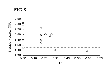
[FIG. 3] FIG. 3 is a graph illustrating the relation between a ratio (F1) of
the total of
the content in mass% of a wax, the content in mass% of a fluorine-based
additive and
the content in mass% of graphite to the total of the content in mass% of a
magnesium
silicate hydroxide powder and the content of TiO2 in a resin coating
containing an
epoxy resin, and the storage modulus of the resin coating.
[FIG. 4] FIG. 4 is a configuration diagram illustrating one example of an oil-
well
metal pipe according to the present embodiment.
[FIG. 5] FIG. 5 is a partial cross-sectional view illustrating a cross section
(longitudinal cross section) parallel to a pipe axis direction of a coupling
of the oil-
well metal pipe illustrated in FIG.4.
[FIG. 6] FIG. 6 is a cross-sectional view parallel to the pipe axis direction
of the oil-
well metal pipe illustrated in FIG. 5, that illustrates a portion in the
vicinity of a pin
of the oil-well metal pipe.
[FIG. 7] FIG. 7 is a cross-sectional view parallel to the pipe axis direction
of the oil-
well metal pipe illustrated in FIG. 5, that illustrates a portion in the
vicinity of a box
of the oil-well metal pipe.
CA 03232468 2024- 3- 20
- 7 -
[FIG. 8] FIG. 8 is a view illustrating an example of an oil-well metal pipe in
which
the pin includes an external thread part but does not include a pin sealing
surface and
a pin shoulder surface, and the box includes an internal thread part but does
not
include a box sealing surface and a box shoulder surface.
[FIG. 9] FIG. 9 is a configuration diagram illustrating an integral type oil-
well metal
pipe according to the present embodiment.
[FIG. 10] FIG. 10 is an enlarged view of a pin contact surface illustrated in
FIG. 6.
[FIG. 11] FIG. 11 is an enlarged view of a box contact surface illustrated in
FIG. 7.
DESCRIPTION OF EMBODIMENTS
[0017]
The present embodiment will be described in detail below with reference to
the accompanying drawings. The same reference symbols will be used throughout
the drawings to refer to the same or like parts, and description thereof will
not be
repeated.
[0018]
The present inventors conducted studies regarding an oil-well metal pipe
which can be fastened with high torque. As a result, the present inventors
obtained
the following findings.
[0019]
Heretofore, a method which increases the coefficient of friction of a resin
coating has been proposed as a method for increasing fastening torque. When
fastening threaded connections together, if resin coatings that each have a
high
coefficient of friction come in contact and slide relative to each other, it
is expected
that the torque when performing fastening will rise. If the torque when
performing
fastening rises, the yield torque will also rise at the same time. That is,
the yield
torque can be used as an indicator as to whether or not an oil-well metal pipe
can be
fastened with high torque. The present inventors included a magnesium silicate
hydroxide powder that is a solid powder in a resin coating containing an epoxy
resin,
adjusted the coefficient of friction of the resin coating, and investigated
the relation
between the coefficient of friction and the yield torque.
[0020]
CA 03232468 2024- 3- 20
- 8 -
FIG. 1 is a graph illustrating the relation between the coefficient of
friction of
a resin coating containing an epoxy resin, and the yield torque. The abscissa
in
FIG. 1 represents the coefficient of friction ( ) of the resin coating
containing an
epoxy resin. The ordinate in FIG. 1 represents the yield torque (ft. lbs.) in
a case
where an oil-well metal pipe on which the resin coating containing an epoxy
resin
was formed was fastened. Here, the term "yield torque" refers to the torque at
a
time when a threaded connection yields when being fastened. The higher the
yield
torque is, the higher the torque with which the threaded connection can be
fastened
will be.
[0021]
Referring to FIG. 1, a correlation coefficient R2 between the coefficient of
friction of the resin coating containing an epoxy resin and the yield torque
was 0.144.
This means that there was almost no correlation between the coefficient of
friction of
the resin coating containing an epoxy resin and the yield torque. Thus it was
found
that, contrary to the expectation of the present inventors, the correlation
between the
coefficient of friction and the yield torque is low. That is, it was found
that the
yield torque cannot be raised by simply increasing the coefficient of friction
of the
resin coating.
[0022]
Therefore, the present inventors conducted further studies with respect to an
oil-well metal pipe which can be fastened with high torque. The present
inventors
focused their attention on the behavior of the resin coating in the final
stage of
fastening. In the final stage of fastening, one resin coating and another
resin
coating come in contact with each other with high interfacial pressure and
slide. At
such time, an external force is applied to each resin coating, and energy
which is
generated by torsion is also applied thereto. If the resistance of the resin
coating to
the external force and the energy generated by torsion is high, in the final
stage of
fastening also, the resin coating will resist the aforementioned external
force and
energy to try to maintain its shape. It is considered that in this case the
torque of the
fastening increases. In this regard, the present inventors considered that
increasing
the dynamic viscoelasticity of the resin coating is effective for increasing
the
resistance to the external force and the energy generated by torsion.
CA 03232468 2024- 3- 20
- 9 -
[0023]
Dynamic viscoelasticity is separated into a storage modulus and a loss
modulus. The term "storage modulus" refers to a component which, of the energy
generated in an object by an external force and strain, is stored within the
object.
The term "loss modulus" refers to a component which, of the energy generated
in an
object by an external force and strain, is diffused to the outside. The
present
inventors considered that the storage modulus of a resin coating, and not the
loss
modulus of a resin coating, influences the yield torque. Therefore, with
respect to a
resin coating containing an epoxy resin, the present inventors investigated
the
relation between the storage modulus of a resin coating and the yield torque.
[0024]
FIG. 2 is a graph illustrating the relation between the storage modulus of a
resin coating containing an epoxy resin, and the yield torque. The abscissa in
FIG.
2 represents the storage modulus (MPa) of the resin coating containing an
epoxy
resin. The ordinate in FIG. 2 represents the yield torque (ft. lbs.) in a case
where an
oil-well metal pipe on which the resin coating containing an epoxy resin was
formed
was fastened.
[0025]
Referring to FIG. 2, a correlation coefficient R2 between the storage modulus
of the resin coating containing an epoxy resin and the yield torque was
0.7082.
This means that there is a correlation between the storage modulus of the
resin
coating containing an epoxy resin and the yield torque. In other words, it was
found
that the yield torque of the oil-well metal pipe can be raised by increasing
the storage
modulus of the resin coating.
[0026]
That is, in contrast to the conventional findings, it was found that the yield
torque cannot be raised by simply increasing the coefficient of friction of a
resin
coating, and that the yield torque can be raised only after increasing the
storage
modulus of the resin coating.
[0027]
The present inventors conducted studies regarding a method for increasing the
storage modulus of a resin coating containing an epoxy resin. As a result, the
CA 03232468 2024- 3- 20
- 10 -
present inventors considered that if an epoxy resin is adopted as the base
material of
a resin coating, and a magnesium silicate hydroxide powder that is a solid
powder is
contained in the resin coating, the storage modulus of the resin coating will
be
increased. Therefore, the present inventors prepared various resin coatings
containing an epoxy resin in an amount within a range of 40.0 to 97.0 mass%,
and
also containing magnesium silicate hydroxide in an amount within a range of
3.0 to
50.0 mass%, and investigated the storage modulus of these resin coatings. As a
result, the present inventors found that even in the case of resin coatings
having the
aforementioned components, the storage modulus decreases in some cases. In
other
words, the storage modulus of a resin coating is not increased by merely
causing the
resin coating to contain a magnesium silicate hydroxide powder.
[0028]
As the result of further studies regarding a method for increasing the storage
modulus of a resin coating containing an epoxy resin, the present inventors
found
that if the components satisfy the following Formula (1), the storage modulus
of the
resin coating can be increased:
(Cw+CF+CG)/(Cmg+CTio2+Csi) 0.28 (1)
where, in Formula (1), a content in mass% of the wax is substituted for Cw, a
content in mass% of the fluorine-based additive is substituted for CF, a
content in
mass% of the graphite is substituted for CG, a content in mass% of the
magnesium
silicate hydroxide powder is substituted for Cmg, a content in mass% of the
TiO2 is
substituted for CTi02, and a content in mass% of the silane coupling agent is
substituted for Csi.
[0029]
Here, it is defined that (Cw+CF+CG)/(Cmg+CTio2+Csi) = Fl. FIG. 3 is a
graph illustrating the relation between Fl in a resin coating containing an
epoxy
resin, and the storage modulus of the resin coating. FIG. 3 is an extract of
one part
of the results of examples which are described later. The abscissa in FIG. 3
represents Fl. The ordinate in FIG. 3 represents the storage modulus (MPa) of
the
resin coating.
[0030]
Referring to FIG. 3, if Fl is 0.28 or less, the storage modulus of the resin
CA 03232468 2024- 3- 20
- 11 -
coating becomes 1.50 MPa or more. Although the reason for this is not certain,
the
present inventors surmise that the reason is as follows. An epoxy resin has a
moderate hardness, and also contains therein a large amount of oxygen (0) or
hydrogen (H). Further, in the case of a magnesium silicate hydroxide powder
and
Ti02, hydroxyl groups and metals such as magnesium or titanium are exposed on
the
surface of the powder, and thus the surface of the powder has polarity.
Therefore, a
hydroxyl group or a metal on the surface of the magnesium silicate hydroxide
powder and TiO2 forms a hydrogen bond with oxygen (0) or hydrogen (H)
contained
in epoxy resin. By this means, the storage modulus of the resin coating
increases.
Further, a silane coupling agent has an alkoxysilyl group and an organic
reactive
group. The alkoxysilyl group and the organic reactive group each chemically
bond
with epoxy resin. Therefore, the silane coupling agent causes cross-linking of
epoxy resins. By this means, the storage modulus of the resin coating
increases.
[0031]
A wax, a fluorine-based additive and graphite do not contain a large amount
of polar moieties such as oxygen (0), and hence the adhesiveness thereof to
epoxy
resin is weak. Therefore, if a magnesium silicate hydroxide powder, TiO2 and a
silane coupling agent are excessively included relative to a wax, a fluorine-
based
additive and graphite, the storage modulus of the resin coating will increase.
Specifically, a ratio of the total of the content in mass% of a wax, the
content in
mass% of a fluorine-based additive and the content in mass% of graphite to the
total
of the content in mass% of a magnesium silicate hydroxide powder, the content
in
mass% of Ti02, and the content in mass% of a silane coupling agent is made
0.28 or
less. By this means, the storage modulus of the resin coating increases.
[0032]
As described above, in contrast to the conventional findings, it was found
that
the yield torque cannot be raised by simply increasing the coefficient of
friction of
the resin coating, and that the yield torque can be raised only by increasing
the
storage modulus of the resin coating. Further, it was found that the storage
modulus
of the resin coating is increased only by adjusting the content of each
component in
the resin coating so as to satisfy the aforementioned Formula (1). By raising
the
yield torque by increasing the storage modulus of the resin coating, an oil-
well metal
CA 03232468 2024- 3- 20
- 12 -
pipe that can also be used for horizontal drilling is obtained. The oil-well
metal
pipe of the present disclosure was completed based on the above findings, and
has
the following structure.
[0033]
[1]
An oil-well metal pipe, including:
a pipe main body including a first end portion and a second end portion,
wherein:
the pipe main body includes:
a pin formed at the first end portion, and
a box formed at the second end portion;
the pin includes:
a pin contact surface including an external thread part; and
the box includes:
a box contact surface including an internal thread part;
the oil-well metal pipe further including:
a resin coating on or above at least one of the pin contact surface and the
box
contact surface,
the resin coating containing:
an epoxy resin: 40.0 to 97.0 mass%,
a magnesium silicate hydroxide powder: 3.0 to 50.0 mass%,
TiO2: 0 to 10.0 mass%,
a wax: 0 to 10.0 mass%,
a fluorine-based additive: 0 to 20.0 mass%,
graphite: 0 to 10.0 mass%,
a rust preventive pigment: 0 to 30.0 mass%,
a coloring pigment: 0 to 10.0 mass%, and
a silane coupling agent: 0 to 10.0 mass%,
and satisfying Formula (1):
(Cw+CF+CG)/(Cmg+CTio2+Csi) 0.28 (1)
where, in Formula (1), a content in mass% of the wax is substituted for Cw, a
content in mass% of the fluorine-based additive is substituted for CF, a
content in
CA 03232468 2024- 3- 20
- 13 -
mass% of the graphite is substituted for CG, a content in mass% of the
magnesium
silicate hydroxide powder is substituted for Cmg, a content in mass% of the
TiO2 is
substituted for CTi02, and a content in mass% of the silane coupling agent is
substituted for Csi.
[0034]
[2]
The oil-well metal pipe according to [1], wherein:
the pin contact surface further includes a pin sealing surface and a pin
shoulder surface, and
the box contact surface further includes a box sealing surface and a box
shoulder surface.
[0035]
Hereunder, the oil-well metal pipe according to the present embodiment will
be described in detail.
[0036]
[Structure of Oil-Well Metal Pipe]
First, the structure of the oil-well metal pipe of the present embodiment will
be described. The oil-well metal pipe has a well-known structure. The
available
types of oil-well metal pipe are a T&C type oil-well metal pipe and an
integral type
oil-well metal pipe. Hereunder, each type of oil-well metal pipe will be
described
in detail.
[0037]
[Case where Oil-Well Metal Pipe 1 is T&C type]
FIG. 4 is a configuration diagram illustrating one example of an oil-well
metal
pipe 1 according to the present embodiment. FIG. 4 is a configuration diagram
illustrating the oil-well metal pipe 1 of a so-called T&C (threaded and
coupled) type.
Referring to FIG. 4, the oil-well metal pipe 1 includes a pipe main body 10.
[0038]
The pipe main body 10 extends in the pipe axis direction. A cross section
perpendicular to the pipe axis direction of the pipe main body 10 is a
circular shape.
The pipe main body 10 includes a first end portion 10A and a second end
portion
10B. The first end portion 10A is an end portion on the opposite side to the
second
CA 03232468 2024- 3- 20
- 14 -
end portion 10B. In the T&C type oil-well metal pipe 1 illustrated in FIG. 4,
the
pipe main body 10 includes a pin tube body 11 and a coupling 12. The coupling
12
is attached to one end of the pin tube body 11. More specifically, the
coupling 12 is
fastened by threading to one end of the pin tube body 11.
[0039]
FIG. 5 is a partial cross-sectional view illustrating a cross section
(longitudinal cross section) that is parallel to the pipe axis direction of
the coupling
12 of the oil-well metal pipe 1 illustrated in FIG. 4. Referring to FIG. 4 and
FIG. 5,
the pipe main body 10 includes a pin 40 and a box 50. The pin 40 is formed at
the
first end portion 10A of the pipe main body 10. When performing fastening, the
pin
40 is inserted into the box 50 of another oil-well metal pipe 1 (not
illustrated), and is
fastened by threading to the box 50 of the other oil-well metal pipe 1.
[0040]
The box 50 is formed at the second end portion 10B of the pipe main body 10.
When performing fastening, the pin 40 of another oil-well metal pipe 1 is
inserted
into the box 50, and the box 50 is fastened by threading to the pin 40 of the
other oil-
well metal pipe 1.
[0041]
[Regarding structure of pin 40]
FIG. 6 is a cross-sectional view of a portion in the vicinity of the pin 40 of
the
oil-well metal pipe 1 illustrated in FIG. 5, that is a cross-sectional view
parallel to the
pipe axis direction of the oil-well metal pipe 1. A dashed line portion in
FIG. 6
represents the structure of the box 50 of another oil-well metal pipe in the
case of
fastening the oil-well metal pipe 1 to another oil-well metal pipe 1.
Referring to
FIG. 6, the pin 40 includes a pin contact surface 400 on the outer peripheral
surface
of the first end portion 10A of the pipe main body 10. When fastening to the
other
oil-well metal pipe 1, the pin contact surface 400 is screwed into the box 50
of the
other oil-well metal pipe 1 and contacts a box contact surface 500 (described
later) of
the box 50.
[0042]
The pin contact surface 400 includes at least an external thread part 41
formed
in the outer peripheral surface of the first end portion 10A. The pin contact
surface
CA 03232468 2024- 3- 20
- 15 -
400 may further include a pin sealing surface 42 and a pin shoulder surface
43. In
FIG. 6, the pin shoulder surface 43 is disposed at the front end face of the
first end
portion 10A, and on the outer peripheral surface of the first end portion 10A,
the pin
sealing surface 42 is disposed further on the front end side of the first end
portion
10A than the external thread part 41. In other words, the pin sealing surface
42 is
disposed between the external thread part 41 and the pin shoulder surface 43.
The
pin sealing surface 42 is provided in a tapered shape. Specifically, the
external
diameter of the pin sealing surface 42 gradually decreases from the external
thread
part 41 toward the pin shoulder surface 43 in the longitudinal direction (pipe
axis
direction) of the first end portion 10A.
[0043]
When performing fastening with another oil-well metal pipe 1, the pin sealing
surface 42 contacts a box sealing surface 52 (described later) of the box 50
of the
other oil-well metal pipe 1. More specifically, during fastening, when the pin
40 is
inserted into the box 50 of the other oil-well metal pipe 1, the pin sealing
surface 42
contacts the box sealing surface 52. Subsequently, when the pin 40 is screwed
further into the box 50 of the other oil-well metal pipe 1, the pin sealing
surface 42
closely contacts the box sealing surface 52. By this means, during fastening,
the pin
sealing surface 42 closely contacts the box sealing surface 52 to thereby form
a seal
that is based on metal-to-metal contact. Therefore, the gastightness can be
increased in each of the oil-well metal pipes 1 that are fastened to each
other.
[0044]
In FIG. 6, the pin shoulder surface 43 is disposed at the front end face of
the
first end portion 10A. In other words, in the pin 40 illustrated in FIG. 6,
the
external thread part 41, the pin sealing surface 42 and the pin shoulder
surface 43 are
disposed sequentially in that order from the center of the pipe main body 10
toward
the first end portion 10A. During fastening to the other oil-well metal pipe
1, the
pin shoulder surface 43 opposes and contacts a box shoulder surface 53
(described
later) of the box 50 of the other oil-well metal pipe 1. More specifically,
during
fastening, the pin shoulder surface 43 contacts the box shoulder surface 53 as
a result
of the pin 40 being inserted into the box 50 of the other oil-well metal pipe
1. By
CA 03232468 2024- 3- 20
- 16 -
this means, during fastening, a high torque can be obtained. Further, the
positional
relation between the pin 40 and the box 50 in the fastening state can be
stabilized.
[0045]
Note that, the pin contact surface 400 of the pin 40 includes at least the
external thread part 41. In other words, the pin contact surface 400 includes
the
external thread part 41, and need not include the pin sealing surface 42 and
the pin
shoulder surface 43. The pin contact surface 400 may include the external
thread
part 41 and the pin shoulder surface 43, and need not include the pin sealing
surface
42.
The pin contact surface 400 may include the external thread part 41 and
the pin
sealing surface 42, and need not include the pin shoulder surface 43.
[0046]
[Regarding structure of box 50]
FIG. 7 is a cross-sectional view of a portion in the vicinity of the box 50 of
the oil-well metal pipe 1 illustrated in FIG. 5, that is a cross-sectional
view parallel to
the pipe axis direction of the oil-well metal pipe 1. A dashed line portion in
FIG. 7
represents the structure of the pin 40 of another oil-well metal pipe 1 in the
case of
fastening the oil-well metal pipe 1 to another oil-well metal pipe 1.
Referring to
FIG. 7, the box 50 includes a box contact surface 500 on the inner peripheral
surface
of the second end portion 10B of the pipe main body 10. When performing
fastening to another oil-well metal pipe 1, the box contact surface 500
contacts the
pin contact surface 400 of the pin 40 of the other oil-well metal pipe 1 when
the pin
40 is screwed into the box 50.
[0047]
The box contact surface 500 includes at least an internal thread part 51
formed
in the inner peripheral surface of the second end portion 10B. When performing
fastening, the internal thread part 51 engages with the external thread part
41 of the
pin 40 of the other oil-well metal pipe 1.
[0048]
The box contact surface 500 may further include the box sealing surface 52
and the box shoulder surface 53. In FIG. 7, on the inner peripheral surface of
the
second end portion 10B, the box sealing surface 52 is disposed further on the
pipe
main body 10 side than the internal thread part 51. In other words, the box
sealing
CA 03232468 2024- 3- 20
- 17 -
surface 52 is disposed between the internal thread part 51 and the box
shoulder
surface 53. The box sealing surface 52 is provided in a tapered shape.
Specifically, the internal diameter of the box sealing surface 52 gradually
decreases
from the internal thread part 51 toward the box shoulder surface 53 in the
longitudinal direction (pipe axis direction) of the second end portion 10B.
[0049]
When performing fastening to another oil-well metal pipe 1, the box sealing
surface 52 contacts the pin sealing surface 42 of the pin 40 of the other oil-
well metal
pipe 1. More specifically, during fastening, when the pin 40 of the other oil-
well
metal pipe 1 is screwed into the box 50, the box sealing surface 52 contacts
the pin
sealing surface 42, and when the pin 40 is screwed in further, the box sealing
surface
52 closely contacts the pin sealing surface 42. By this means, during
fastening, the
box sealing surface 52 closely contacts the pin sealing surface 42 to thereby
form a
seal that is based on metal-to-metal contact. Therefore, the gastightness can
be
increased in each of the oil-well metal pipes 1 that are fastened to each
other.
[0050]
The box shoulder surface 53 is disposed further on the pipe main body 10 side
than the box sealing surface 52. In other words, in the box 50, the box
shoulder
surface 53, the box sealing surface 52 and the internal thread part 51 are
disposed
sequentially in that order from the center of the pipe main body 10 toward the
front
end of the second end portion 10B. When performing fastening to another oil-
well
metal pipe 1, the box shoulder surface 53 opposes and contacts the pin
shoulder
surface 43 of the pin 40 of the other oil-well metal pipe 1. More
specifically,
during fastening, the box shoulder surface 53 contacts the pin shoulder
surface 43 as
a result of the pin 40 of the other oil-well metal pipe 1 being inserted into
the box 50.
By this means, during fastening, a high torque can be obtained. Further, the
positional relation between the pin 40 and the box 50 in the fastening state
can be
stabilized.
[0051]
The box contact surface 500 includes at least the internal thread part 51.
When performing fastening, the internal thread part 51 of the box contact
surface 500
of the box 50 contacts the external thread part 41 of the pin contact surface
400 of the
CA 03232468 2024- 3- 20
- 18 -
pin 40 in a manner such that the internal thread part 51 corresponds to the
external
thread part 41. The box sealing surface 52 contacts the pin sealing surface 42
in a
manner such that the box sealing surface 52 corresponds to the pin sealing
surface 42.
The box shoulder surface 53 contacts the pin shoulder surface 43 in a manner
such
that the box shoulder surface 53 corresponds to the pin shoulder surface 43.
[0052]
In a case where the pin contact surface 400 includes the external thread part
41 and does not include the pin sealing surface 42 and the pin shoulder
surface 43,
the box contact surface 500 includes the internal thread part 51 and does not
include
the box sealing surface 52 and the box shoulder surface 53. In a case where
the pin
contact surface 400 includes the external thread part 41 and the pin shoulder
surface
43 and does not include the pin sealing surface 42, the box contact surface
500
includes the internal thread part 51 and the box shoulder surface 53 and does
not
include the box sealing surface 52. In a case where the pin contact surface
400
includes the external thread part 41 and the pin sealing surface 42 and does
not
include the pin shoulder surface 43, the box contact surface 500 includes the
internal
thread part 51 and the box sealing surface 52 and does not include the box
shoulder
surface 53.
[0053]
The pin contact surface 400 may include a plurality of the external thread
parts 41, may include a plurality of the pin sealing surfaces 42, and may
include a
plurality of the pin shoulder surfaces 43. For example, the pin shoulder
surface 43,
the pin sealing surface 42, the external thread part 41, the pin sealing
surface 42, the
pin shoulder surface 43, the pin sealing surface 42 and the external thread
part 41
may be disposed in that order on the pin contact surface 400 of the pin 40 in
the
direction from the front end of the first end portion 10A toward the center of
the pipe
main body 10. In such case, the internal thread part 51, the box sealing
surface 52,
the box shoulder surface 53, the box sealing surface 52, the internal thread
part 51,
the box sealing surface 52 and the box shoulder surface 53 are disposed in
that order
on the box contact surface 500 of the box 50 in the direction from the front
end of the
second end portion 10B toward the center of the pipe main body 10.
[0054]
CA 03232468 2024- 3- 20
- 19 -
In FIG. 6 and FIG. 7 a so-called "premium joint" is illustrated in which the
pin 40 includes the external thread part 41, the pin sealing surface 42 and
the pin
shoulder surface 43, and the box 50 includes the internal thread part 51, the
box
sealing surface 52 and the box shoulder surface 53. However, as described
above,
the pin 40 may include the external thread part 41 and need not include the
pin
sealing surface 42 and the pin shoulder surface 43. In this case, the box 50
includes
the internal thread part 51 and does not include the box sealing surface 52
and the
box shoulder surface 53. FIG. 8 is a view illustrating one example of the oil-
well
metal pipe 1 in which the pin 40 includes the external thread part 41 and does
not
include the pin sealing surface 42 and the pin shoulder surface 43, and the
box 50
includes the internal thread part 51 and does not include the box sealing
surface 52
and the box shoulder surface 53.
[0055]
[Case where oil-well metal pipe 1 is integral type]
The oil-well metal pipe 1 illustrated in FIG. 4, FIG. 5 and FIG. 8 is a so-
called
"T&C type" oil-well metal pipe 1, in which the pipe main body 10 includes the
pin
tube body 11 and the coupling 12. However, the oil-well metal pipe 1 according
to
the present embodiment may be an integral type instead of a T&C type.
[0056]
FIG. 9 is a configuration diagram of an integral type oil-well metal pipe 1
according to the present embodiment. Referring to FIG. 9, the integral type
oil-well
metal pipe 1 includes a pipe main body 10. The pipe main body 10 includes a
first
end portion 10A and a second end portion 10B. The first end portion 10A is
disposed on the opposite side to the second end portion 10B. As described
above,
in the T&C type oil-well metal pipe 1, the pipe main body 10 includes the pin
tube
body 11 and the coupling 12. In other words, in the T&C type oil-well metal
pipe 1,
the pipe main body 10 is constituted by fastening two separate members (the
pin tube
body 11 and the coupling 12). In contrast, in the integral type oil-well metal
pipe 1,
the pipe main body 10 is formed in an integral manner.
[0057]
The pin 40 is formed at the first end portion 10A of the pipe main body 10.
When performing fastening, the pin 40 is inserted in and screwed into the box
50 of
CA 03232468 2024- 3- 20
- 20 -
another integral type oil-well metal pipe 1, and thereby fastened to the box
50 of the
other integral type oil-well metal pipe 1. The box 50 is formed at the second
end
portion 10B of the pipe main body 10. When performing fastening, the pin 40 of
another integral type the oil-well metal pipe 1 is inserted in and screwed
into the box
50, to thereby fasten the box 50 to the pin 40 of the other integral type oil-
well metal
pipe 1.
[0058]
The structure of the pin 40 of the integral type oil-well metal pipe 1 is the
same as the structure of the pin 40 of the T&C type oil-well metal pipe 1
illustrated
in FIG. 6. Similarly, the structure of the box 50 of the integral type oil-
well metal
pipe 1 is the same as the structure of the box 50 of the T&C type oil-well
metal pipe
1 illustrated in FIG. 7. Note that, in FIG. 6 and FIG. 7, the pin shoulder
surface 43,
the pin sealing surface 42 and the external thread part 41 in the pin 40 are
disposed in
that order from the front end of the first end portion 10A toward the center
of the
pipe main body 10. Therefore, the internal thread part 51, the box sealing
surface
52 and the box shoulder surface 53 in the box 50 are disposed in that order
from the
front end of the second end portion 10B toward the center of the pipe main
body 10.
However, similarly to the pin contact surface 400 of the pin 40 of the T&C
type oil-
well metal pipe 1, it suffices that the pin contact surface 400 of the pin 40
of the
integral type oil-well metal pipe 1 includes at least the external thread part
41.
Further, similarly to the box contact surface 500 of the box 50 of the T&C
type oil-
well metal pipe 1, it suffices that the box contact surface 500 of the box 50
of the
integral type oil-well metal pipe 1 includes at least the internal thread part
51.
[0059]
In short, the oil-well metal pipe 1 of the present embodiment may be a T&C
type or may be an integral type.
[0060]
[Resin coating]
The oil-well metal pipe 1 of the present embodiment includes a resin coating
100 on or above at least one of the pin contact surface 400 and the box
contact
surface 500. FIG. 10 is an enlarged view of the pin contact surface 400
illustrated
in FIG. 6. FIG. 11 is an enlarged view of the box contact surface 500
illustrated in
CA 03232468 2024- 3- 20
- 21 -
FIG. 7. As illustrated in FIG. 10 and FIG. 11, the oil-well metal pipe 1
according to
the present embodiment may include the resin coating 100 on or above both the
pin
contact surface 400 and the box contact surface 500. However, a configuration
may
also be adopted in which the oil-well metal pipe 1 according to the present
embodiment includes the resin coating 100 on or above only one surface among
the
pin contact surface 400 and the box contact surface 500. For example, in a
case
where the resin coating 100 is provided on or above the pin contact surface
400 as
illustrated in FIG. 10, the resin coating 100 need not be provided on or above
the box
contact surface 500. Further, in a case where the resin coating 100 is
provided on
or above the box contact surface 500 as illustrated in FIG. 11, the resin
coating need
not be provided on the pin contact surface 400. In other words, the oil-well
metal
pipe 1 according to the present embodiment includes the resin coating 100 on
or
above the pin contact surface 400 and/or on or above the box contact surface
500.
[0061]
[Components of resin coating]
The resin coating 100 has the following components.
[0062]
Epoxy resin: 40.0 to 97.0 mass%
An epoxy resin is the base material of the resin coating 100. Here, the term
"base material" refers to the component that is contained in the largest
amount in the
resin coating 100. An epoxy resin has a moderate hardness, and also contains a
large amount of oxygen (0) or hydrogen (H) therein. Therefore, the epoxy resin
easily forms a hydrogen bond with a hydroxyl group or metals such as magnesium
and titanium which are exposed on the surface of a magnesium silicate
hydroxide
powder and TiO2. The epoxy resin also chemically bonds with a silane coupling
agent. If the content of the epoxy resin is less than 40.0 mass%, the hardness
of the
resin coating 100 will decrease, and the resin coating 100 will be liable to
peel off
when fastening and loosening are repeated. On the other hand, if the content
of the
epoxy resin is more than 97.0 mass%, a sufficient amount of other components,
including a magnesium silicate hydroxide powder, cannot be sufficiently
contained,
and consequently there is a possibility that the galling resistance and the
yield torque
of the oil-well metal pipe 1 may decrease. Accordingly, the content of the
epoxy
CA 03232468 2024- 3- 20
- 22 -
resin is within a range of 40.0 to 97.0 mass%. A preferable lower limit of the
content of the epoxy resin is 43.0 mass%, more preferably is 45.0 mass%, and
further
preferably is 50.0 mass%. A preferable upper limit of the content of the epoxy
resin
is 95.0 mass%, more preferably is 90.0 mass%, and further preferably is 89.0
mass%.
[0063]
Magnesium silicate hydroxide powder: 3.0 to 50.0 mass%
A magnesium silicate hydroxide powder increases the storage modulus of the
resin coating 100. A hydroxyl group and a polar group containing magnesium are
exposed on the surface of the magnesium silicate hydroxide powder. Therefore,
the
magnesium silicate hydroxide powder easily forms hydrogen bonds with oxygen
(0)
or hydrogen (H) within the epoxy resin. It is considered that by the magnesium
silicate hydroxide powder forming hydrogen bonds inside the epoxy resin, the
storage modulus of the resin coating 100 increases. If the content of the
magnesium
silicate hydroxide powder is less than 3.0 mass%, the aforementioned effect is
not
obtained. On the other hand, if the content of the magnesium silicate
hydroxide
powder is more than 50.0 mass%, defects will occur in the formation of the
resin
coating 100. Therefore, the content of the magnesium silicate hydroxide powder
is
within a range of 3.0 to 50.0 mass%. A preferable lower limit of the content
of the
magnesium silicate hydroxide powder is 5.0 mass%, more preferably is 7.0
mass%,
and further preferably is 10.0 mass%. A preferable upper limit of the content
of the
magnesium silicate hydroxide powder is 45.0 mass%, more preferably is 40.0
mass%, and further preferably is 35.0 mass%.
[0064]
TiO2: 0 to 10.0 mass%
TiO2 is a component that is optionally contained, and it need not be
contained.
When contained, TiO2 increases the storage modulus of the resin coating 100.
TiO2
is a powder. A hydroxyl group and a polar group containing titanium are
exposed
on the surface of the TiO2 powder. Therefore, the TiO2 easily forms hydrogen
bonds with oxygen (0) or hydrogen (H) within the epoxy resin. It is considered
that by the TiO2 forming hydrogen bonds inside the epoxy resin, the storage
modulus
of the resin coating 100 increases. However, if the content of TiO2 is more
than
10.0 mass%, the TiO2 will promote abrasive wear, and may cause the galling
CA 03232468 2024- 3- 20
- 23 -
resistance of the oil-well metal pipe 1 to decrease. Therefore, the content of
TiO2 is
within a range of 0 to 10.0 mass%. When TiO2 is to be contained, a preferable
lower limit of the content of TiO2 is 0.1 mass%, more preferably is 0.2 mass%,
and
further preferably is 0.5 mass%. When TiO2 is to be contained, a preferable
upper
limit of the content of TiO2 is 5.0 mass%, more preferably is 4.0 mass%, and
further
preferably is 3.0 mass%.
[0065]
Wax: 0 to 10.0 mass%
Wax is a component that is optionally contained, and it need not be contained.
When contained, wax increases the lubricity of the resin coating 100. However,
if
the content of wax is more than 10.0 mass%, the hardness of the resin coating
100
will decrease, and the resin coating 100 will be liable to peel off when
fastening and
loosening are repeated. Therefore, the content of wax is within a range of 0
to 10.0
mass%. When wax is to be contained, a preferable lower limit of the content of
wax is 1.0 mass%, more preferably is 2.0 mass%, and further preferably is 3.0
mass%. When wax is to be contained, a preferable upper limit of the content of
wax is 9.0 mass%, more preferably is 8.0 mass%, and further preferably is 5.0
mass%.
[0066]
The wax is, for example, one or more types selected from a group consisting
of animal waxes, vegetable waxes, mineral waxes, and synthetic waxes. More
specifically, the wax is one or more types selected from a group consisting of
bees
wax, spermaceti wax (the foregoing are animal waxes), Japan wax, carnauba wax,
candelilla wax and rice wax (the foregoing are vegetable waxes), paraffin wax,
microcrystalline wax, petrolatum, montan wax, ozocerite and ceresin (the
foregoing
are mineral waxes), oxidized wax, polyethylene wax, polypropylene wax, Fischer-
Tropsch wax, amide wax and hydrogenated castor oil (castor wax) (the foregoing
are
synthetic waxes). More preferably, the wax is one or more types selected from
the
group consisting of polyethylene wax and polypropylene wax. The resin coating
100 may contain a plurality of types of wax. In a case where the resin coating
100
contains a plurality of types of wax, the term "content of wax" means the
total
content of the plurality of types of wax.
CA 03232468 2024- 3- 20
- 24 -
[0067]
Fluorine-based additive: 0 to 20.0 mass%
A fluorine-based additive is a component that is optionally contained, and it
need not be contained. When contained, the fluorine-based additive increases
the
lubricity of the resin coating 100. However, if the content of the fluorine-
based
additive is more than 20.0 mass%, the hardness of the resin coating 100 will
decrease, and the resin coating 100 will be liable to peel off when fastening
and
loosening are repeated. Therefore, the content of the fluorine-based additive
is
within a range of 0 to 20.0 mass%. When a fluorine-based additive is to be
contained, a preferable lower limit of the content of the fluorine-based
additive is 1.0
mass%, more preferably is 5.0 mass%, and further preferably is 8.0 mass%. When
a fluorine-based additive is to be contained, a preferable upper limit of the
content of
the fluorine-based additive is 18.0 mass%, more preferably is 15.0 mass%, and
further preferably is 10.0 mass%.
[0068]
The term "fluorine-based additive" is a generic term for additives containing
fluorine. The fluorine-based additive is, for example, one or more types
selected
from the group consisting of perfluoropolyether (PFPE) and
polytetrafluoroethylene
(PTFE). The resin coating 100 may contain a plurality of types of fluorine-
based
additive. In a case where the resin coating 100 contains a plurality of types
of
fluorine-based additive, the term "content of the fluorine-based additive"
means the
total content of the plurality of types of fluorine-based additive.
[0069]
Graphite: 0 to 10.0 mass%
Graphite is a component that is optionally contained, and it need not be
contained. When contained, graphite increases the lubricity of the resin
coating
100. However, if the content of graphite is more than 10.0 mass%, the hardness
of
the resin coating 100 will decrease, and the resin coating 100 will be liable
to peel off
when fastening and loosening are repeated. Therefore, the content of graphite
is
within a range of 0 to 10.0 mass%. When graphite is to be contained, a
preferable
lower limit of the content of graphite is 1.0 mass%, more preferably is 3.0
mass%,
and further preferably is 5.0 mass%. When graphite is to be contained, a
preferable
CA 03232468 2024- 3- 20
- 25 -
upper limit of the content of graphite is 9.0 mass%, more preferably is 8.0
mass%,
and further preferably is 7.0 mass%.
[0070]
Rust preventive pigment: 0 to 30.0 mass%
A rust preventive pigment is a component that is optionally contained, and it
need not be contained. When contained, the rust preventive pigment increases
the
anti-rust properties of the resin coating 100. However, if the content of the
rust
preventive pigment is more than 30.0 mass%, defects will occur in the
formation of
the resin coating 100. Therefore, the content of the rust preventive pigment
is
within a range of 0 to 30.0 mass%. When a rust preventive pigment is to be
contained, a preferable lower limit of the content of the rust preventive
pigment is
1.0 mass%, more preferably is 2.0 mass%, and further preferably is 4.0 mass%.
When a rust preventive pigment is to be contained, a preferable upper limit of
the
content of the rust preventive pigment is 25.0 mass%, more preferably is 20.0
mass%, and further preferably is 10.0 mass%.
[0071]
The rust preventive pigment is not particularly limited as long as it is a
well-
known pigment that increases the anti-rust properties of the resin coating
100. The
rust preventive pigment is, for example, one or more types selected from a
group
consisting of zinc phosphate, aluminum tripolyphosphate, aluminum phosphite, a
metal soap of a carboxylic acid, and a sulfonate. The resin coating 100 may
contain
a plurality of types of rust preventive pigment. In a case where the resin
coating
100 contains a plurality of types of rust preventive pigment, the term
"content of the
rust preventive pigment" means the total content of the plurality of types of
rust
preventive pigment.
[0072]
Coloring pigment: 0 to 10.0 mass%
A coloring pigment is a component that is optionally contained, and it need
not be contained. When contained, the coloring pigment colors the resin
coating
100 and facilitates visual recognition of damage to the resin coating 100.
However,
if the content of the coloring pigment is more than 10.0 mass%, defects will
occur in
the formation of the resin coating 100. Therefore, the content of the coloring
CA 03232468 2024- 3- 20
- 26 -
pigment is within a range of 0 to 10.0 mass%. When a coloring pigment is to be
contained, a preferable lower limit of the content of the coloring pigment is
0.1
mass%, more preferably is 0.2 mass%, and further preferably is 0.5 mass%. When
a coloring pigment is to be contained, a preferable upper limit of the
coloring
pigment is 8.0 mass%, more preferably is 5.0 mass%, and further preferably is
3.0
mass%.
[0073]
The coloring pigment is not particularly limited as long as it is a well-known
pigment which can color the resin coating 100. The coloring pigment is, for
example, one or more types selected from a group consisting of copper
phthalocyanine, zinc oxide, carbon black, yellow iron oxide, iron oxide, and
chromium hydroxide. The resin coating 100 may contain a plurality of types of
coloring pigment. In a case where the resin coating 100 contains a plurality
of
types of coloring pigment, the term "content of the coloring pigment" means
the total
content of the plurality of types of coloring pigment.
[0074]
Silane coupling agent: 0 to 10.0 mass%
A silane coupling agent is a component that is optionally contained, and it
need not be contained. When contained, the silane coupling agent increases the
adhesiveness of the resin coating 100. By this means, during repeated
fastening and
loosening of the oil-well metal pipe 1, the silane coupling agent suppresses
delamination of the resin coating 100. The silane coupling agent also causes
cross-
linking of epoxy resin and thereby increases the storage modulus of the resin
coating
100. However, if the content of the silane coupling agent is more than 10.0
mass%,
defects will occur in the formation of the resin coating 100. Therefore, the
content
of the silane coupling agent is within a range of 0 to 10.0 mass%. When a
silane
coupling agent is to be contained, a preferable lower limit of the content of
the silane
coupling agent is 0.1 mass%, more preferably is 0.2 mass%, and further
preferably is
0.5 mass%. When a silane coupling agent is to be contained, a preferable upper
limit of the content of the silane coupling agent is 8.0 mass%, more
preferably is 6.0
mass%, and further preferably is 4.0 mass%.
[0075]
CA 03232468 2024- 3- 20
- 27 -
Other components: 0 to 10.0 mass%
Other components are components that are optionally contained, and these
components need not be contained. The term "other components" refers to, for
example, one or more types selected from the group consisting of an antiseptic
agent
and an antioxidant agent. When other components are contained, the content of
the
other components is 10.0 mass% or less in total. That is, the content of the
other
components is within a range of 0 to 10.0 mass% in total.
[0076]
The resin coating 100 may be a resin coating 100 consisting of: an epoxy
resin: 40.0 to 97.0 mass%, a magnesium silicate hydroxide powder: 3.0 to 50.0
mass%, TiO2: 0 to 10.0 mass%, a wax: 0 to 10.0 mass%, a fluorine-based
additive: 0
to 20.0 mass%, graphite: 0 to 10.0 mass%, a rust preventive pigment: 0 to 30.0
mass%, a coloring pigment: 0 to 10.0 mass%, a silane coupling agent: 0 to 10.0
mass% and other components: 0 to 10.0 mass%.
[0077]
[Formula (1)]
The resin coating 100 satisfies Formula (1):
(Cw+CF+CG)/(Cmg+CTio2+Csi) 0.28 (1)
where, in Formula (1), a content in mass% of the wax is substituted for Cw, a
content in mass% of the fluorine-based additive is substituted for CF, a
content in
mass% of the graphite is substituted for CG, a content in mass% of the
magnesium
silicate hydroxide powder is substituted for Cmg, a content in mass% of the
TiO2 is
substituted for CTi02, and a content in mass% of the silane coupling agent is
substituted for Csi.
[0078]
Here, it is defined that (Cw+CF+CG)/(Cmg+CTio2+Csi) = F1. If F1 is more
than 0.28, the content of the wax, fluorine-based additive and graphite for
which it is
difficult to form hydrogen bonds with the epoxy resin will be too large
relative to the
content of the magnesium silicate hydroxide powder and TiO2 which easily form
hydrogen bonds with the epoxy resin and also relative to the content of the
silane
coupling agent that causes cross-linking of epoxy resin. In such a case, the
storage
modulus of the resin coating 100 will decrease. Therefore, Fl 0.28. The upper
CA 03232468 2024- 3- 20
- 28 -
limit of Fl is preferably 0.25, more preferably is 0.20, further preferably is
0.15, and
more preferably is 0.10. Fl may be 0.
[0079]
By the components of the resin coating 100 satisfying Formula (1), the
storage modulus of the resin coating 100 increases. As a result, the yield
torque of
the oil-well metal pipe 1 that includes the resin coating 100 rises.
[0080]
[Storage modulus of resin coating]
Whilst the storage modulus of the resin coating 100 is not particularly
limited,
the higher the storage modulus is, the more preferable it is. If the storage
modulus
of the resin coating 100 is 1.50 MPa or more, the yield torque of the oil-well
metal
pipe 1 that includes the resin coating 100 can be markedly raised. Therefore,
the
storage modulus of the resin coating 100 is preferably 1.50 MPa or more. The
lower limit of the storage modulus of the resin coating 100 is more preferably
1.55
MPa, further preferably is 1.70 MPa, and more preferably is 2.00 MPa. Whilst
the
upper limit of the storage modulus of the resin coating 100 is not
particularly limited,
for example, the upper limit is 10.00 MPa.
[0081]
[Method for measuring storage modulus]
The storage modulus of the resin coating 100 is measured by the following
method. The composition for forming the resin coating 100 is clamped between a
heating plate and a geometry of a rotary rheometer. The storage modulus at a
time
when the geometry is rotated at a constant speed in one direction is measured.
The
test specimen is set in the rotary rheometer at room temperature, heated
rapidly to
210 C, and the storage modulus when the test specimen has been held for 20
minutes
at 210 C is measured. The measurement conditions are as follows: measurement
temperature: 210 C; timing at which to measure storage modulus: when 20
minutes
has passed after the start of the measurement; frequency: 1Hz; environment:
under
nitrogen gas.
[0082]
[Thickness of resin coating]
CA 03232468 2024- 3- 20
- 29 -
The thickness of the resin coating 100 is not particularly limited. The
thickness of the resin coating 100 is, for example, 1 to 100 'um. In this
case, the
yield torque of the oil-well metal pipe 1 can be more stably increased. The
lower
limit of the thickness of the resin coating 100 is preferably 2 lam, more
preferably is
lam, and further preferably is 10 lam. The upper limit of the thickness of the
resin
coating 100 is preferably 50 lam, more preferably is 40 lam, and further
preferably is
30 lam.
[0083]
[Method for measuring thickness of resin coating]
The thickness of the resin coating 100 is measured by the following method.
A probe of an electromagnetic induction type film thickness measuring
instrument is
brought into contact with the pin contact surface 400 or the box contact
surface 500
on which the resin coating 100 is formed. The probe has an electromagnet, and
when a magnetic body is brought close to it, electromagnetic induction occurs,
and
its voltage changes depending on the distance between the probe and the
magnetic
body. The thickness of the resin coating 100 is determined from the change in
voltage amount. The measurement locations are twelve locations (twelve
locations
that are at 00, 30 , 60 , 90 , 120 , 150 , 180 , 210 , 240 , 270 , 300 and
330 ) in
the tube circumferential direction of the oil-well metal pipe 1. The
arithmetic mean
of the measurement results of the twelve locations is taken to be the
thickness of the
resin coating 100.
[0084]
[Chemical composition of pipe main body]
Chemical composition of the pipe main body 10 of the oil-well metal pipe 1
according to the present embodiment is not particularly limited. Accordingly,
the
kind of steel of the pipe main body 10 of the oil-well metal pipe 1 is not
particularly
limited. The pipe main body 10 may be formed of, for example, carbon steel,
stainless steel, alloy steel or the like. Accordingly, the oil-well metal pipe
1 may be
a steel pipe made of Fe-based alloy or an alloy pipe represented by a Ni-based
alloy
pipe. Here, the steel pipe is, for example, a low-alloy steel pipe, a
martensitic
stainless steel pipe, and a duplex stainless steel pipe. Among alloy steels,
high alloy
steels such as a Ni-based alloy and duplex stainless steels that contain
alloying
CA 03232468 2024- 3- 20
- 30 -
elements such as Cr, Ni and Mo have high corrosion resistance. Therefore by
using
these high alloy steels as the pipe main body 10, excellent corrosion
resistance is
obtained in a corrosive environment that contains hydrogen sulfide or carbon
dioxide
or the like.
[0085]
[Production method]
A method for producing the oil-well metal pipe 1 according to the present
embodiment will be described hereunder.
[0086]
The method for producing the oil-well metal pipe 1 according to the present
embodiment includes a preparation process, an application process, and a
hardening
process. The hardening process is performed after the application process.
[0087]
[Preparation process]
In the preparation process, the oil-well metal pipe 1 having the pipe main
body 10 that includes the pin 40 including the pin contact surface 400 that
includes
the external thread part 41, and the box 50 including the box contact surface
500 that
includes the internal thread part 51 is prepared. As described above, the oil-
well
metal pipe 1 according to the present embodiment has a well-known structure.
In
other words, in the preparation process it suffices to prepare the oil-well
metal pipe 1
that has a well-known structure.
[0088]
[Application process]
In the application process, a composition is applied onto at least one of the
pin
contact surface 400 and the box contact surface 500. The composition is a
composition for forming the aforementioned resin coating 100. The composition
contains epoxy resin: 40.0 to 97.0 mass%, a magnesium silicate hydroxide
powder:
3.0 to 50.0 mass%, TiO2: 0 to 10.0 mass%, a wax: 0 to 10.0 mass%, a fluorine-
based
additive: 0 to 20.0 mass%, graphite: 0 to 10.0 mass%, a rust preventive
pigment: 0 to
30.0 mass%, a coloring pigment: 0 to 10.0 mass%, and a silane coupling agent:
0 to
10.0 mass%, and satisfies Formula (1). The composition also contains a
solvent.
CA 03232468 2024- 3- 20
- 31 -
The composition for forming the resin coating 100 is the same as the
composition of
the resin coating 100 described above, excluding a solvent.
[0089]
The composition can be produced, for example, by melting or dispersing the
epoxy resin, the magnesium silicate hydroxide powder and, as necessary, other
components in the solvent and mixing them. The solvent is, for example, one or
more types selected from the group consisting of water, alcohol and an organic
solvent. The solvent may contain a small amount of a surfactant. The
proportion
of the solvent is not particularly limited. It suffices to adjust the
proportion of the
solvent to an appropriate viscosity according to the application method. The
proportion of the solvent is, for example, within a range of 40 to 60 mass%
when
taking the total of all components other than the solvent as 100 mass%.
[0090]
The method of applying the composition on the pin contact surface 400 and/or
the box contact surface 500 is not particularly limited, and a well-known
method
may be used. For example, the composition in solution form is applied on the
pin
contact surface 400 and/or the box contact surface 500 by spray coating. In
this
case, the viscosity of the composition is to be adjusted so that it can be
applied by
spray coating in an environment at normal temperature and normal pressure.
Another application method, such as brushing or dipping may be employed as the
method for applying the composition on the pin contact surface 400 and/or the
box
contact surface 500, instead of spray application.
[0091]
[Hardening process]
In the hardening process, the applied composition is hardened to form the
resin coating 100. By heating the composition that was applied onto at least
one of
the pin contact surface 400 and the box contact surface 500, the composition
is
subjected to thermal curing and the solid resin coating 100 is formed. The
heating
method is not particularly limited, and a well-known method may be used. The
heating method is, for example, a method in which the oil-well metal pipe 1 on
which the composition has been applied is inserted into a well-known heating
CA 03232468 2024- 3- 20
- 32 -
furnace and heated. The heating temperature is, for example, 200 to 250 C, and
the
heating time is, for example, 5 to 30 minutes.
[0092]
The oil-well metal pipe 1 according to the present embodiment is produced by
the above processes.
[0093]
[Preconditioning treatment process]
The method for producing the oil-well metal pipe 1 according to the present
embodiment may further include a preconditioning treatment process prior to
the
application process. In the preconditioning treatment process, for example,
one or
more types of treatment selected from the group consisting of a pickling
treatment, a
blasting treatment and an alkaline degreasing treatment is performed.
[0094]
In the case of performing a pickling treatment, for example, the pin contact
surface 400 and/or the box contact surface 500 is immersed in a strongly
acidic
solution such as sulfuric acid, hydrochloric acid, nitric acid, hydrofluoric
acid or a
mixture of these acids, to thereby increase the surface roughness of the pin
contact
surface 400 and/or the box contact surface 500. In the case of performing a
blasting
treatment, for example, sand blasting is performed in which a blast material
(an
abrasive) is mixed with compressed air, and the mixture is propelled onto the
pin
contact surface 400 and/or the box contact surface 500. In this case, the
surface
roughness of the pin contact surface 400 and/or the box contact surface 500
increases.
[0095]
Note that, with respect to preconditioning treatment process, the pin contact
surface 400 and the box contact surface 500 may be subjected to the same
processes
or may be subjected to different processes to each other. Further, the
preconditioning treatment process may be performed only on the pin contact
surface
400, or may be performed only on the box contact surface 500.
[0096]
The oil-well metal pipe 1 according to the present embodiment is produced by
the above processes. However, the production method described above is one
example of a method for producing the oil-well metal pipe 1 according to the
present
CA 03232468 2024- 3- 20
- 33 -
embodiment, and the present embodiment is not limited to the production method
described above. The oil-well metal pipe 1 according to the present embodiment
may also be produced by another method.
[Example]
[0097]
The advantageous effects of the oil-well metal pipe of the present
embodiment are described more specifically hereunder by way of examples. The
conditions adopted in the following examples are one example of conditions
which
are employed for confirming the workability and advantageous effects of the
oil-well
metal pipe of the present embodiment. Accordingly, the oil-well metal pipe of
the
present embodiment is not limited to this one example of the conditions.
[0098]
In the examples, compositions for forming resin coatings were prepared, and
the storage modulus of the respective resin coatings was evaluated. The
specific
details are described in the following.
[0099]
[Storage modulus evaluation test]
Compositions having the components shown in Table 1 were prepared.
Each composition contained a solvent in addition to the components described
in
Table 1. A mixed solution of water, alcohol and a surfactant was used as the
solvent. Each composition was applied onto a heating plate of a rotary
rheometer
(manufactured by Anton Parr Japan K. K., model number MCR302). The
composition was clamped between the heating plate and the geometry, and the
storage modulus when the geometry was rotated at a constant speed in one
direction
was measured. The test specimen was set in the rotary rheometer at room
temperature, heated rapidly to 210 C, and the storage modulus when the test
specimen had been held for 20 minutes at 210 C was measured. The following
measurement conditions were adopted: measurement temperature: 210 C; timing at
which to measure storage modulus: after 20 minutes passed after the start of
the
measurement; frequency: 1Hz; environment: under nitrogen gas. Note that, the
respective compositions were applied so that the thickness of each resin
coating was
within the range of 30 to 40 lam.
CA 03232468 2024- 3- 20
,-,
,E.)3
,,.
.
-34-
0
[0100]
[Table 1]
TABLE 1
Resin Coating Composition
Evaluation Result
Magnesium
Fluorine- Rust
Silane
Test Silicate
Coloring
Hydroxide
Number
Epoxy Resin TiO2 Wax Based
Graphite Preventive Pigment Coupling F1 Storage
Modulus
(mass%) Powder
(mass%) (mass%) (mass%) Additive (mass%) Pigment Agent (MPa)
(mass%) (mass%)
(mass%)
(mass%)
1 89.9 0.0 1.4 0.0 0.0 0.0 7.6
1.1 0.0 0.00 1.25
2 57.0 0.0 0.0 0.0 12.0 0.0 22.0
9.0 0.0 - 1.11
3 77.6 2.4 0.0 0.0 12.0 0.0 7.0
1.0 0.0 5.00 1.33
4 85.6 3.4 0.0 0.0 0.0 0.0 7.0
1.0 3.0 0.00 1.78
77.1 14.6 0.0 0.0 0.0 0.0 4.9 1.0 2.4
0.00 2.44
6 77.1 19.5 0.0 0.0 0.0 0.0 0.0
1.0 2.4 0.00 2.38
7 48.6 39.0 1.4 0.0 0.0 0.0 7.5
1.0 2.5 0.00 1.50
8 49.8 40.0 1.4 0.0 0.0 0.0 7.7
1.1 0.0 0.00 1.54
9 84.4 2.4 0.0 4.9 0.0 0.0 7.3
1.0 0.0 2.04 1.45
67.5 14.7 0.0 9.8 0.0 0.0 4.9 1.0 2.1
0.58 1.38
11 72.3 14.7 0.0 4.9 0.0 0.0 4.9
1.0 2.2 0.29 1.41
12 73.1 15.0 0.0 3.0 0.0 0.0 4.9
1.0 3.0 0.17 1.80
13 73.1 15.0 0.0 0.0 3.0 0.0 4.9
1.0 3.0 0.17 1.69
14 73.1 15.0 0.0 0.0 0.0 3.0 4.9
1.0 3.0 0.17 1.99
65.1 20.0 0.0 3.0 3.0 0.0 4.9 1.0 3.0
0.26 2.01
16 65.7 20.0 1.4 0.0 2.0 2.0 4.9
1.0 3.0 0.16 2.24
17 64.7 20.0 1.4 3.0 0.0 2.0 4.9
1.0 3.0 0.20 2.00
18 63.7 20.0 1.4 2.0 2.0 2.0 4.9
1.0 3.0 0.25 1.95
19 41.1 6.0 0.0 32.0 8.0 7.0 4.9
1.0 0.0 7.83 1.34
93.6 2.4 0.0 0.0 0.0 0.0 0.0 1.0 3.0
0.00 1.30
- 35 -
[0101]
[Evaluation results]
Referring to Table 1, with respect to the resin coatings of Test Numbers 4 to
8
and 12 to 18, the content of each component was appropriate, and the
composition
satisfied Formula (1). Therefore, the storage modulus was 1.50 MPa or more.
The resin coating of each of Test Numbers 4 to 8 and 12 to 18 was able to
raise the
yield torque of the oil-well metal pipe.
[0102]
On the other hand, in the resin coatings of Test Numbers 1 and 2, the
magnesium silicate hydroxide was not contained. Consequently, the storage
modulus was less than 1.50 MPa. Therefore, the respective resin coatings of
Test
Numbers 1 and 2 could not raise the yield torque of the oil-well metal pipe.
[0103]
In the resin coatings of Test Numbers 3 and 9, the content of the magnesium
silicate hydroxide powder was too low. Moreover, the composition did not
satisfy
Formula (1). Consequently, the storage modulus was less than 1.50 MPa.
Therefore, the respective resin coatings of Test Numbers 3 and 9 could not
raise the
yield torque of the oil-well metal pipe.
[0104]
In the resin coatings of Test Numbers 10 and 11, although the content of each
component was appropriate, the composition did not satisfy Formula (1).
Consequently, the storage modulus was less than 1.50 MPa. Therefore, the
respective resin coatings of Test Numbers 10 and 11 could not raise the yield
torque
of the oil-well metal pipe.
[0105]
In the resin coating of Test Number 19, the content of wax was too large, and
further, the composition did not satisfy Formula (1). Consequently, the
storage
modulus was less than 1.50 MPa. Therefore, the resin coating of Test Number 19
could not raise the yield torque of the oil-well metal pipe.
[0106]
In the resin coating of Test Number 20, the content of a magnesium silicate
hydroxide powder was too small. Consequently, the storage modulus was less
than
CA 03232468 2024- 3- 20
- 36 -
1.50 MPa. Therefore, the resin coating of Test Number 20 could not raise the
yield
torque of the oil-well metal pipe.
[0107]
An embodiment of the present disclosure has been described above.
However, the foregoing embodiment is merely an example for implementing the
present disclosure. Accordingly, the present disclosure is not limited to the
above
embodiment, and the above embodiment can be appropriately modified within a
range which does not deviate from the gist of the present disclosure.
REFERENCE SIGNS LIST
[0108]
1 Oil-well metal pipe
Pipe Main Body
10A First End Portion
10B Second End Portion
11 Pin Tube Body
12 Coupling
40 Pin
41 External Thread Part
42 Pin Sealing Surface
43 Pin Shoulder Surface
50 Box
51 Internal Thread Part
52 Box Sealing Surface
53 Box Shoulder Surface
100 Resin Coating
400 Pin Contact Surface
500 Box Contact Surface
CA 03232468 2024- 3- 20