Note: Descriptions are shown in the official language in which they were submitted.
WO 2023/049320
PCT/US2022/044495
PORTABLE MAGNETIC RESONANCE IMAGER
CROSS-REFERENCE TO RELATED APPLICATION
This application claims the benefit of U.S. Provisional Patent Application
Serial No.
63/248,090 filed September 24, 2021, the entirety of which is incorporated by
reference herein as
if fully set forth.
BACKGROUND OF THE INVENTION
The present invention is directed to a portable Magnetic Resonance Imager
(pMRI) and
more particularly a pMRI utilizing Nitrogen Vacancy Diamond (NVD) as the
magnetic sensor as
well as a novel magnet configuration designed to produce a useful magnetic
field outside the
physical constraints of the magnet, to produce images representing the
arrangement and
concentration of hydrogen protons, or other magnetic resonance structures, in
humans, animals,
and any other substance.
In order to understand the present invention, some background information
about the
need for a small, portable, low-field, MRI is helpful.
1.1 Problem
Traditional Magnetic Resonance Imaging (MRI) visualizes anatomical structure
and
functions non-invasively with high spatial and temporal resolution. Yet, to
overcome the low
sensitivity inherent in inductive detection of weakly polarized nuclear spins,
clinical MRI
scanners employ cryogenically-cooled superconducting magnets producing very
high magnetic
fields. Commonly found at 1.5-7 Tesla (T), these powerful magnets are massive,
and have very
strict infrastructure demands that preclude operation in many environments.
MRI scanners are
costly to purchase, site, and maintain.
MRI scanners are built around massive superconducting magnets, and the total
installed
cost of MRI systems is typically $1 M per tesla of magnetic field. The high
cost of these devices
limits the number of scanners on site, and it requires medical facilities to
carefully prioritize
patients. Additionally, these massive scanners preclude mobile operation, and
preclude many
locations including surgical suites, triage and primary care suites.
1
CA 03232720 2024- 3- 21
WO 2023/049320
PCT/US2022/044495
Operation at low magnetic fields would enable imaging in environments where
high
magnetic fields would be contraindicated (such as in the presence of nearby
ferrous materials)
and would raise the potential for scanners to be built and installed at
significantly reduced total
installed cost. Low magnetic fields would also enable open geometry designs
that would ease
patient handling and positioning.
1.2 Nitrogen Vacancy Diamond Magnetometers
Within the past few years, magnetometers using nitrogen-vacancy color centers
in
diamond, have been considered for a wide range of applications because of
their high spatial
resolution, simplicity of use, but most importantly for pMRI, is their
application at room
temperature. See Grosz, A., Haji-Sheikh, M.J., Mukhopadhy, ay, S.C. (2017).
High Sensitivity
Magnetometers (p 553). Switzerland: Springer International Publishing.
As seen in Figure 1, the NVD 148 consists of a normal tetrahedral diamond
lattice with
one carbon atom substituted with a nitrogen atom and a vacancy adjacent to the
nitrogen atom, as
shown in the figure. Because of the tetrahedral shape of the crystal lattice,
there are four possible
orientations of the nitrogen-vacancy axis. The axis is defined as the line
connecting the nitrogen
atom with the vacancy.
Each NV center, due to the dangling electrons from the three adjacent carbon
atoms and
the nitrogen atom, has an electronic energy level ground state, 3A2, and an
excited state, 'E. The
optical transition between these states is a 637nm wavelength. Energy from a
532nm green laser
raises the energy level of the electrons from the ground state to the excited
state, and
fluorescence decay from the excited state to the ground state emits light in
the 637nm to 800nm
wavelength range. There are energy sublevels that are dependent on the
magnitude of the
magnetic field coupled to the NV center due to the Zeeman effect. This effect
is linearly
dependent on the magnitude of the field. Given that there are four possible
orientations of the
NV center, it is possible to measure the effects of the magnetic field
contribution along each axis
and derive directionality of the source of the magnetic field as well as
magnitude.
Because the difference in the energy sublevels is within the range of
microwaves, it is
possible to apply a microwave signal that resonates with the one of the
transitions. When this
2
CA 03232720 2024- 3- 21
WO 2023/049320
PCT/US2022/044495
happens the fluorescence is spoiled, causing the intensity at that frequency
to decrease.
Combining these effects, one can measure the magnetic field intensity based on
the magnitudes
of the fluorescence and the direction can be derived from the frequency
deviation.
Because the sensitivity of NVD is within the realm of the most sensitive
magnetometers
(SQUIDs, Vapor Cells, ANIS), but does not require the supporting cryogenics
and is much
smaller than the Faraday Induction Coils, it is the perfect magnetometer for
pMRI.
1.2.1 Fundamental Parameters
1.2.1.1 Proton Density
Proton density refers to the number of protons in a unit volume that are
available for MR
measurement. See Liang, Z., Lauterbur, P.C., (2000). Principals of magnetic
resonance imaging
(pp. 66-67). New York: Institute of Electrical and Electronics Engineers, Inc.
Since only two
spin states are available for hydrogen, the hydrogen nucleus (proton) will
line up with the
external magnetic field either parallel or anti-parallel to the direction of
the external magnetic
field.
However, the parallel spin quanta is the lower of the two energy levels. This
means that
there are approximately 10 extra protons precessing parallel to the external
magnetic field for
every million protons than anti-parallel. This exceedingly small number is
offset by the fact that
there are Avogadro numbers (6.022 x 10²³) of protons in the volume being
measured. Using a
volume element (voxel) equivalent to medical MRIs of 0.125 cubic-mm, there are
approximately
8.34 x 10¹⁸ protons in a voxel. Thus there are approximately 8.52 x 10¹⁴
hydrogen atoms that can
be measured See Case, RU (2008) Reducing eddy currents in high magnetic field
environments
(pp. 20-21). Master's thesis, University of Central Florida, Orlando.
This spin density gives weight to the voxel in the form of intensity of the
image. For
positive image depiction (white = high density), tissue (or other object) will
show up white for
high proton density and black for samples with no protons that can be
measured.
1.2.1.2 Larmor Frequency
To create a useful image of the human body, modern medical MRIs rely on the
interaction of nuclear spin with a high magnitude external magnetic field, Bo.
The interaction of
a spinning proton (hydrogen nucleus) and an external magnetic field results in
the precession of
3
CA 03232720 2024- 3- 21
WO 2023/049320
PCT/US2022/044495
the proton spin about the axis of the external magnetic field. In essence the
majority of the proton
spins "line up" with the external magnetic field. The frequency, wo, of the
precession is:
(no = yBo
where y is a fundamental constant called the gyromagnetic ratio. For protons y
has the
value 2.68 x 10⁸ radians/second/Tesla or 42.6 MHz/T. This precession frequency
is called the
Larmor frequency. See Hacke, E.M., Brown, R.W., Thompson, M.R., & Venkatesan,
R. (1999),
Magnetic resonance imaging: Physical principals and sequence design (p. 4).
New York: A
John Wiley & Sons, Inc. For most medical MRIs the bore field is either 1.5T or
3.0T and the
resulting precession frequency is either 63.9 MHz or 127.8 MHz. High magnetic
field strength is
used in stationary fixed-site MRIs because it provides an inherently greater
signal-to-noise ratio.
Most clinical electromagnets use Niobium-Titanium (NbTi) or other
superconducting
materials surrounded by copper, forming a large coil. The coil is integrated
with additional
superconducting coils that are active electromagnetic shielding. Additional
passive shielding is
also used. The superconducting coils are then surrounded by layers of vacuum
insulation, liquid
helium that causes the NbTi coils to enter the superconducting phase, and then
liquid nitrogen to
reduce vaporization of the very expensive liquid helium. See Bushong, S.C.
(1996). Magnetic
resonance imaging: physical and biological principals (p. 140) . St. Louis,
MO: Mosby ¨ Year
Book, Inc. The copper coating allows for superconducting "quench" in case of
power failure or
loss of superconductivity in the "ramp down- of the magnet.
However, lower field strength, such as that used in pMRI, is advantageous for
its smaller
size, lower weight, decreased complexity, and many other considerations.
1.2.1.3 Relaxation Times
In order to line up with an applied external magnetic field, a precessing
proton will give
up energy to the surrounding lattice of nearby atoms in the form of thermal
energy. The rate at
which this occurs gives rise to the longitudinal magnetization of the sample,
and that time
constant is called Ti or "spin-lattice relaxation time." To set up the
measurement of Ti, the
precessing protons are "perturbed" into the transverse (perpendicular to the
Bo field) axis or into
the anti-parallel (180 degree shift) with an RF pulse. This RF pulse
simultaneously causes the
precessions to achieve the same phase organization.
4
CA 03232720 2024- 3- 21
WO 2023/049320
PCT/US2022/044495
Another important parameter used in MRI is called the "spin-spin relaxation
time" or T2,
which is a measure of the rate at which the phase relationship of protons
decay as the proton
precessions line up with the bore field (parallel to the bore field). Since
there are always
localized variations in the magnetic field, which result in variations in the
Larmor frequency,
each individual spin is exposed to a different field strength which leads to
the loss of coherence.
The proton spin density, relaxation times, and to lesser degrees the magnetic
susceptibility and chemical shift parameters are used to construct the
familiar MRI images.
SUMMARY OF THE INVENTION
This Summary is provided to introduce a selection of concepts in simplified
form that are
further described below in the Detailed Description. This Summary is not
intended to identify key
features or essential features of the claimed subject matter, nor is it
intended to be used to limit the
scope of the claimed subject matter. Furthermore, the claimed subject matter
is not limited to
limitations that solve any or all disadvantages noted in any part of this
disclosure.
A portable magnetic resonance imager has a probe. One or more magnets are
disposed in
the probe, creating at least one magnetic field to precess protons at a
target. A magnetometer
disposed in the probe has a light source and a nitrogen vacancy diamond. The
light source
projects a light on the nitrogen vacancy diamond. The nitrogen vacancy diamond
fluoresces in
response to the light. A photodetector detects the fluorescence and produces a
signal in response
thereto indicative of the decaying of precessing protons having precessed in
the presence of the
one or more magnets.
These and other embodiments, features, aspects, and advantages of the
invention will
become better understood with regard to the following description, appended
claims and
accompanying drawings.
BRIEF DESCRIPTION OF THE DRAWINGS
In order to facilitate a more robust understanding of the application,
reference is now
made to the accompanying drawings, in which like elements are referenced with
like numerals.
These drawings should not be construed to limit the application and are
intended only to be
illustrative. The foregoing aspects and the attendant advantages of the
present invention will
CA 03232720 2024- 3- 21
WO 2023/049320
PCT/US2022/044495
become more readily appreciated by reference to the following detailed
description, when taken
in conjunction with the following accompanying drawings:
Figure 1 is a representation of an NVD crystal cell as known in the art;
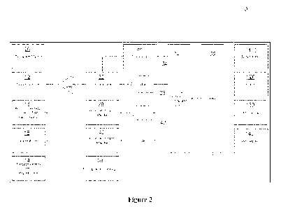
Figure 2 shows a block diagram of a portable MRI system constructed in
accordance with
the invention;
Figure 3 is a top perspective view of a portable magnetic resonance imager
constructed in
accordance with one embodiment of the invention,
Figure 4 is a top perspective view of a portable magnetic resonance imager
display
constructed in accordance with one embodiment of the invention;
Figure 5 shows a solenoid field plot, according to an aspect of this
disclosure;
Figure 6 shows a multi-solenoid field plot, according to an aspect of this
disclosure;
Figure 7 is a perspective view of Golay coils, according to an aspect of this
disclosure;
Figure 8 is a field plot of the Golay coils, according to an aspect of this
disclosure;
Figure 9 is a block diagram of the pM1t1 magnet control system in accordance
with one
embodiment of the invention;
Figure 10 is depicts the shifted bore field of a magnet in accordance with the
invention,
Figure 11 a graph of the field strength as a function of distance along the Y
axis of the
bore magnet in accordance with the invention;
Figure 12 is a block diagram of a system for driving a non homogeneous
external field
magnet in accordance with the invention;
Figure 13 is a block diagram of a transmit antenna system constructed in
accordance with
the invention;
Figure 14 is a block diagram of an NVD magnetometer constructed in accordance
with
the invention;
Figure 15 is a block diagram of an NVD sensor system constructed in accordance
with
the invention,
Figure. 16 is a diagram of the NVD crystal structure;
6
CA 03232720 2024- 3- 21
WO 2023/049320
PCT/US2022/044495
Figure 17 is a diagram of an NV center electronic energy levels;
Figure 18 is a diagram of the optically detected magnetic resonance in
accordance with
the invention;
Figure 19 is a diagram of the optically detected magnetic resonance spectrum
in
accordance with the invention;
Figure. 20 is a perspective view of a cubical NVD as used in accordance with
the
invention;
Figure 21 is a perspective view of a cubical NVD with internal retro
reflection as used in
accordance with another embodiment of the invention;
Figure 22 is a perspective view of a cubical NVD showing internal reflection
as exhibited
by the NVD in accordance with yet another embodiment of the invention;
Figure 23 is a perspective view of a cylindrical NVD as used in accordance
with a further
embodiment of the invention;
Figure 24 is a perspective view of a spherical NVD as used in accordance with
a further
embodiment of the invention;
Figure 25 is a perspective view of magnets for biasing a sensor in accordance
with the
invention;
Figure 26 is a perspective view of magnets for biasing a sensor in accordance
with
another embodiment of the invention;
Figure 27 is a perspective view of magnets for biasing a sensor in accordance
with yet
another embodiment of the invention;
Figure 28 is perspective view a microwave spoiler stnicture in accordance with
the
invention; and
Figure 29 a perspective view of an NVD sensor assembly constructed in
accordance with
the invention.
7
CA 03232720 2024- 3- 21
WO 2023/049320
PCT/US2022/044495
Reference symbols or names are used in the figures to indicate certain
components,
aspects or features shown therein. Reference symbols common to more than one
figure indicate
like components, aspects or features shown therein.
2.0 Detailed Description of the Preferred Embodiments
2.1 Portable Magnetic Resonance Imager
Disclosed is a Portable Magnetic Resonance Imager (pMRI). A brief description
of the
functions blocks is followed by a more detailed description.
Two magnet systems work together to form the useful magnetic field designed to
align
proton precessions. In order to supplement the nonhomogeneous external-field
electromagnet, a
set of permanent magnets are disclosed. These permanent magnets are designed
such that the
produced magnetic field aligns with the main field produced by the
nonhomogeneous
electromagnet.
The nonhomogeneous external-field electromagnet then produces an aligned
magnetic
field as well as gradient fields to produce a spatial distinction among the
measured precessing
protons. This external field extends beyond the physical extents of the
magnet, and is enclosed in
a hand-held probe that allows the user to direct the useful field to any
biological or other object
for which precessing protons are to be measured.
Reference is now made to Figure 2 in which a block diagram of the pMRI,
generally
indicated as 10, and constructed in accordance with the invention is provided.
As known in the
art pMRI 10 includes a power source 110, an interface 120, a mechanical
structure 130 and a
Graphical User Interface 140 as generally known in the art, unless otherwise
described below,
for operating pMRI 10
A CPU 22 provides feedback based control of the sensor components of pMRI 10.
Specifically, CPU 22 provides control inputs to a pulse generation, timing and
control unit 24
which in turn provides control outputs magnets 16, 18, 20 and a magnetometer
14 as described
below in more detail. Control signals are produced by control unit 24 and
processed by an RF
modulator 32 and RF synthesizer for modulating the direct input to RF
modulator to drive a
transmit antenna 12.
8
CA 03232720 2024- 3- 21
WO 2023/049320
PCT/US2022/044495
At the same time control unit 24 provides inputs to power and control
amplifiers 28, 40
for operating non homogeneous external field electromagnet 18 and gradient
coils 16
respectively. The control signals produced by control unit 24 are shaped by
respective digital to
analog converters (DAC) 26, 34, 42 prior to being operated upon. It is known
in the art that a
single DAC may be used for operation upon each of the outputs of control unit
24.
A magnetometer 14, including a nitrogen vacancy diamond, monitors for the
magnetic
field at a target object, having been subject to the magnetic fields of
magnets 16, 18, 20.
Magnetometer 14 also operates under the control of control unit 24 and
provides a signal
corresponding to the measured magnetic field at the target and provides an
input, conditioned by
signal conditioning unit 38, as feedback to CPU 22.
Transmit antenna 12 in the form of a coil, in a preferred non limiting
embodiment, is
powered by RE amplifier 30, and perturbs the precessing protons in a target by
adding energy to
the proton spin system to increase the precession angle, increase the anti-
parallel population, and
synchronize the phase relationship of the precessing protons.
The Nitrogen Vacancy Diamond (NVD) magnetometer 14 then measures the magnetic
field in spatial as well as temporal coordinates as the precession protons de-
phase and return to a
lower energy state small-angle precession. Further, modulation of the magnetic
field under the
control of control unit 24, and in turn magnets 16-20, allows the precession
vector to alternately
randomize and align. The measurement of directionality and intensity of the
measured magnetic
signature of each voxel allows a reconstruction of the data to form an image
representative of the
structure and type of biological tissue or other magnetic resonant substance
being measured.
All of the functionality is managed and controlled by appropriately selected
microprocessors and operating software in CPU 22. Functionality is selected by
the user through
hard and soft controls and indicators as well as displays of the data in a
manner useful to the
diagnosis of the data.
Power is supplied by system power 110 and may include by nonlimiting example,
universal sources including 120VAC, 60Hz sources typically found in the
Western hemisphere,
220VAC, 50Hz sources typically found in Eastern hemisphere, and all manner of
remote,
battery, solar, and other energy sources.
9
CA 03232720 2024- 3- 21
WO 2023/049320
PCT/US2022/044495
The pMRI 100 is housed and supported by appropriate relocatable stands 200
with
facilities for mounting of the electronics, GUI displays 210, controls,
indictors, and the probe
214. A notional depiction of a pMRI housing is shown in Figure 3.
The display section 210, including GUI interface of the pMRI 10 is a high
definition full
color, high refresh rate (to support full motion video imaging).
The novel and unique probe 214 contains the magnetic system (including magnets
16-20)
for producing the useful magnetic field as well as the NVD magnetometer sensor
14. A notional
depiction of the pMRI display 210 and probe 214 are shown in the figure.
1.2.2 Magnet System
Useful magnetic fields are produced in only two ways: through the use of
magnetic
materials (permanent magnets) and passing current through a conductor
(electromagnets). The
shape of the magnetic field depends entirely on the physical arrangement of
magnetic material or
the path of the conductor.
A number of well-known shapes occur for permanent magnets: the bar (round or
square
cross section), and the horseshoe (a bar bent around on itself). The most
common form of
electromagnet is the solenoid. Variations of permanent magnets occur to form
other useful
configurations, such as the fields in electric motors. Coils of wire are
formed in a wide variety of
forms for specific purposes, such as armature windings, coils for beam forming
in television,
radar, antennas, and of course, prior art MR1 equipment.
Knowledge of the basic concepts of the field structure for various
configurations of
permanent magnet and wire forms leads the inventor to conceptually devise a
potentially
advantageous magnetic field configuration. Superposition of more than one
arrangement of coil
and magnet can lead to ever more complex field configurations. The goal of the
acceptable field
configuration is sufficient strength to align the hydrogen atoms, yet
sufficient gradient to allow
discrimination of the hydrogen density at the spatial coordinates under
investigation to be
discerned from surrounding coordinates.
Homogeneity is necessary, in a typical MRI, to differentiate between certain
tissue types
and to capture spatial information ¨ "where in space the signal is coming
from.- All of this
becomes much less important as long as the value of the Bo field is known. If
so, as long as no
two points in the space being measured are the same, spatial information is
preserved. As long as
CA 03232720 2024- 3- 21
WO 2023/049320
PCT/US2022/044495
the absolute Bo field is known, any differences in tissue can be calculated
out. For example, the
resonances created by fat and water are only 3.5 ppm. So, as long as Bo is
known within that
tolerance, tissues can be distinguished.
A very fast two-dimensional pure phase encoding technique, similar to the CPMG
sequence, can be used on highly inhomogeneous fields and reduces the
acquisition time by at
least two orders of magnitude.
1.2.2.1 Solenoid
As shown in Figure 4, an example of a simple solenoid for one exemplary
embodiment
of the bore coil, is provided. Specialized forms of this are used for typical
MRIs, where the
internal magnetic field (red, see Figures 5,6) is generated to maximize the
proton alignment for
the largest signal to noise ratio. However, the portion of the field deemed
useful is contained
completely within the physical confines of the magnet.
In medical MRI systems, the concentration lies in the "red" areas R where the
field is
strongest and, with the help of shim coils and gradient coils, the field
strength is very uniform
across a specific volume. In this application, our interest lies in the fact
that the field is not
uniform (natural gradient), and although not as strong as the central volume,
is sufficiently strong
for imaging purposes. Additional coil structures focus on making the external
field linear or well
defined for useful imaging purposes. The field does not have to be linear
¨just well known.
Image processing techniques can further discern specific locations within the
volume of interest.
1.2.2.2 Multi-Solenoid
The Multi-Solenoid design is modeled to investigate the supposition that the
near field
linearization occurs with stacked coil configurations. Additionally, field
strength is increased
representing the ability to create stronger signals by increased hydrogen spin
populations. A
representative multi-solenoid design is shown in the next figure.
The -red" section R of the bore field is moved to one end of the magnet
(Figure 6).
However, it is not this portion of the field that is useful. Rather, the green
and yellow portion
extending beyond the physical limits of the magnet are of interest.
11
CA 03232720 2024- 3- 21
WO 2023/049320
PCT/US2022/044495
1.2.2.3 Golay Coil
The Golay coil is a pair of saddle shaped coils 702, 704 designed to create a
gradient in
the vicinity of the curved sections. Each linear section cancels out the field
of its neighbor due to
symmetry. The model is shown in Figure 7.
In the model shown in Figure 7, each coil passes a current in such a manner
that the
upper coil 702 adds to the field strength in the region of interest, and the
lower coil 704 subtracts
or weakens the field in the region of interest.
By the right-hand rule, current flows in the positive x-axis direction in the
section located
closest to the origin. This direction of current flow causes current to flow
towards the negative x-
axis in the curved section of the upper coil furthest away from the origin.
Thus, the magnetic
field points towards the positive z-axis.
Current flowing in the opposite manner in the lower coil causes its magnetic
field to point
in the negative z-axis and by superposition of fields, will subtract from a
magnetic field pointing
towards the positive z-axis.
A field plot of the Golay coils, as seen in Figure 8, Indicates the field
intensity with
gradually diminishing magnitude as the distance from the curved section
increases. What is not
shown is the direction of the field. The direction becomes apparent as the
Golay Coil field is
superimposed with the solenoid.
Figure 9, shows a block diagram of a preferred nonlimiting embodiment of the
pMRI
magnet control system, generally indicated as 900 of pIVIRI 10. Magnet control
system 900, as
indicated above includes CPU 22 providing control signals to control unit 24.
Control unit 24 in
turn provides control signals to power and control amplifier 40, which in turn
provides signals
for controlling operation of gradient coil 16.
Gradient coil 16 actually includes a plurality of Golay coils 900a-900n. A
respective
sensor probe 910a-910n is associated with a respective Golay coil 900a-900n.
Power control
amplifier 40 includes one or more current sources 920a-920n associated with a
respective Golay
coil 900a-900n for providing current to activate each respective one of
gradient coils 16. A
respective lock in amplifier 930a-930n of power and control amplifier 40
receives the signals
from respective sensor probes 910a-910n, amplifies the signal and inputs the
signal as a
feedback, via an analog to digital converter 940, to CPU 22.
12
CA 03232720 2024- 3- 21
WO 2023/049320
PCT/US2022/044495
Each Golay coil 900a-900d is driven by a respective computer controlled
current source
920a-920n and individually sensed by sensors 910a-91On to provide feedback to
the computer
(CPU 22) for precision control and manipulation of the magnetic field
gradients by CPU 22.
1.2.2.4 Nonhomogeneous Bore Magnet
There are a number of reasons for having a homogeneous field, such as
minimizing
adverse interactions of proton spins with its surroundings. For clinical
applications, a magnetic
field that varies by just a few parts per million over a spherical volume of
50cm is typical. See
Jin, J. (1999), Electromagnetic analysis and design in magnetic resonance
imaging (p. 22). Boca
Raton, FL: CRC
While a number of coil configurations are capable of producing a homogeneous
magnetic
field, a purpose-designed set of Helmholtz coils (co-axially arranged
solenoids as described
above) is best suited for medical MRI. However, in all electromagnet designs
capable of
producing homogeneous fields, the useful field is inside the physical
constraints of the magnet.
Despite the desire to maintain a homogeneous magnetic field, if the magnetic
field was
perfectly uniform across the entire sample, the Larmor frequency would be the
same for all
points in the sample and it would be impossible to determine spatial
differences within the
sample. To create spatial differences in Larmor frequencies, and thus an
image, x, y, and z
gradient fields are purposefully imposed on the bore field, which violates the
desire to maintain a
homogenous field. Yet, we are still able to obtain a useful image.
Figure 10 shows a one-dimensional aspect of the invention, where the bore
field is
simultaneously shifted to produce a useful magnetic field outside the physical
extents of the
magnet, and the Golay coils shift the slope of the magnetic field in order to
produce a gradient
that creates a spatial differential in the field so that specific Larmor
frequencies can be measured
that represent the concentration of precessing protons in the volume of
interest.
A plot of the field strength versus distance along the "Y" axis is shown in
Figure 11..
Starting at the Y=0 point, which represents the edge of the magnet, and
progressing to the right
(increasing Y), the field magnitude increases to the maximum, then tapers in a
controlled
fashion, essentially producing a useful magnetic field in one dimension.
The invention simply adds Golay coils in orthogonal relationship to produce
the useful
magnetic field in two dimensions. The addition of permanent magnets to bolster
the magnitude
13
CA 03232720 2024- 3- 21
WO 2023/049320
PCT/US2022/044495
of the field allows for reduced size and strength of the nonhomogeneous bore
magnet which in
turn reduces power dissipation, weight, cost, and other factors.
As seen in Figure 12, in a non limiting embodiment showing the use of the
nonhomogeneous external field magnet 18, like numerals being used to identify
like structure,
similar manner to the Golay coils, a bore coil 180 and each field shaping coil
(solenoid coil)
182a-182n will be driven by computer controlled current sources 280a-280n with
feedback
provided by individual sensor probes 184a-184n amplified by an associated lock
in amp 382a-
282n that allow the computer (CPU 22) to ensure the correct magnitude bore
field is produced.
This also allows for computer controlled temporal changes to the bore field. A
block diagram of
the pMRI magnetic field control system is shown in the Figure 12.
Again, the operation of magnets 180a-182n are operated under the control of
CPU 22
which provides control signals to control unit 24, which in turn provides
inputs to respective
current sources 280a-280d of power and control amplifier 28. the respective
current out puts
from power and control amplifier 28 drive respective magnets 180-182n of non
homogeneous
external field magnet 18. CPU 22 controls the current applied, in part, in
response to outputs
from associated sensor probes 184a-184n monitoring magnets 180, 182a-182n.
They in effect
form a feedback loop.
1.2.3 Scanning System
In general, the prior art MR1 sets up a very uniform bore field and then sets
of a precise
linear gradient. This creates a well-known spatial field. Then, the precessing
protons are
energized, allowed to relax, and the emitted energy detected. This is
performed in a linear
fashion to match the linear arrangement of the field.
However, this is not necessary if the field configuration is known. Any shape
field can
then be scanned and the information extracted from the data. In order to do
this, a "rubber band"
mode scanning technique is applied where the scanning follows the field shape.
As the field
shape changes, whether linearly or in some other fashion, the scanning speeds
and accelerations
change to match.
This can be applied both physically and mathematically, or both, which
significantly
reduces "artifacts not only in an inhomogeneous field but in a spatial and
time varying field.
14
CA 03232720 2024- 3- 21
WO 2023/049320
PCT/US2022/044495
Further, techniques involved in spread spectrum communications, where signals
are
purposefully spread in bandwidth to avoid signal detection, and even drop
signal levels below
noise thresholds, are to be employed in reverse to "extract" signals in the
presence of noise. A
major contributor to image inhomogeneity in medical MR1 machines is the
presence of eddy
currents.
A block diagram of the pMRI scanning system is shown in the Figure 13. Like
numerals
are utilized to identify like structure as described throughout the
specification.
1.2.4 Sensor System
The favored sensing technology for large medical MRIs is the Faraday Induction
Coil.
Faraday Induction Coils, which come in many shapes and sizes for various
applications, are all
essentially radio frequency antennas. See Young, S.W. (1988). Magnetic
resonance imaging (p.
20). New York: Raven Press, Ltd. Once the bore field is applied to line up the
precessing
protons, and the gradient field is applied to create spatial differences in
the sample, a set of
specific pulse sequences is applied to the RF coils which transmit the RF
energy into the
precessing proton matrix and "perturb" them. When the precessing protons
return to a naturally
lower energy state, they -re-radiate" the energy in the form of an
electromagnetic field that is
measured typically by the same coils. It is this detected energy that is
processed to form images
of the underlying sample. Faraday induction coils are easily manipulated into
efficient
transmitters and receivers of radio frequency energy. However, they suffer
from significant (as
compared to other NMR sensors) noise and sensitivity issues, especially in
fields less than 1T.
For the Portable Magnetic Resonance Imager, a new and novel application of the
Nitrogen-Vacancy Diamond (NVD) magnetometer is applied. A typical NVD
magnetometer
notional layout is shown in Figure 14. See Grosz, A., Ed. (2017). High
Sensitivity
Magnetometers (p559). Switzerland: Springer International Publishing.
As seen in Figure 14, an NVD magnetometer 1400 includes a pump laser 1401,
preferable in the green wavelength. Pump laser 1401 outputs a light beam to a
dichroic beam
splitter 1420 which directs the beam through a lens 1440 to be focused on NVD
crystal 1480. A
microwave source 1402 emits microwaves at NVD crystal 1480 which in response
thereto, emits
light through beam splitter 1420 and optics 1460 as known in the art to be
received at photodiode
1462.
CA 03232720 2024- 3- 21
WO 2023/049320
PCT/US2022/044495
Figure 15 is a block diagram of the pMRI NVD sensor system 1500 constructed in
accordance with the invention is provided; like numerals are utilized to
indicate like structure.
CPU 22 outputs control signals to pulse generator 24 to output signals
Nitrogen vacancy
diamond magnetometer 14. The control signals are modified RF synthesizer 36,
RF modulator
32 and then amplified by RF amplifier 30 prior to input to magnetometer 14.
Return signals from
magnetometer 14 are input to CPU 22 after being processed by analog to digital
converter 152
and signal conditioning unit 38.
NVD magnetometer 14 includes a pump laser 1140, emitting light at the 532nm
wavelength in a preferred non limiting embodiment. The light beam is operated
upon by optics
142 to then be directed to NVD 148. A microwave spoiler 146 operates on NVD
148, causing
NVD to emit a beam of light at a second wavelength diverted by optics 142 to a
Si avalanche
photodetector 150 which emits an output indicative of the light
characteristics back to CPU 22
through signal conditioning unit 38.
In this way a 532nm laser 1140, or any energy pump source in the 450nm and
637nm
range (the absorption band of the NVD 148) is used to excite the NV color
center. As the color
center energy spontaneously fluoresces, the resulting signal is detected by a
silicon avalanche
photodetector 150, or other photodetector. Since the fluoresce frequency is
dependent on the
m= 1 sub-energy levels, which are manipulated by the external magnetic field
through the
Zeeman effect, along with the fact there are four possible orientations of the
N-V alignment in
the diamond atomic structure, there are then a total of eight possible
fluorescence frequencies.
A microwave signal, swept across the frequency range of the eight possible
fluorescence
frequencies, will interfere with the fluorescence as the microwave frequency
resonates with the
sub-level energy, causing the signal to weaken or diminish. The resulting
eight "dips" in the
spectrum, along with knowledge of the crystal orientation of the diamond,
allow the signal to be
read and the computer to calculate the direction and magnitude of the magnetic
signal produced
by the decaying precessing protons. As a result, an image of this data can be
produced that
provides the diagnostician a representative image of the underlying biological
tissue or the
magnetic resonant substance being measured.
1.2.4.1 Optically Detected Magnetic Resonance with NVD
16
CA 03232720 2024- 3- 21
WO 2023/049320
PCT/US2022/044495
The NVD crystal structure, as shown Figure 16, consists of a tetrahedral
diamond lattice
with one carbon atom substituted by a nitrogen atom. Adjacent to the nitrogen
atom is a vacancy
or "hole" in the crystal lattice. The tetrahedral structure allows four
different orientations of the
N-V alignment.
Each of the three carbon atoms adjacent to the NV center contributes a
dangling electron.
The nitrogen atom contributes two electrons, and a sixth electron completes
the negative charge
state NV-, which is useful for magnetometry.
The energy level structure of the NV- ("NV") center is shown in Figure 16. The
energy
transition between the 3A2 ground state and the 3E energized state corresponds
to 637nm red
light. See Figure 17. But, because the phonon (collective excitation of the
atoms) sidebands
broaden the NV absorption and fluorescence spectra by hundreds of nanometers
in wavelength, a
readily available 532nm green laser can be used to excite the NV center.
The spin-triplet state 3A2 is of particular importance as magnetic fields
couple to the NV
center through the Zeeman effect. See Grosz, A., Ed. (2017). High Sensitivity
Magnetometers.
(p556). Switzerland: Springer International Publishing. If the NV center is
exposed to a magnetic
field, the energies of the sublevels depend linearly on the magnitude of the
magnetic field. A
detailed explanation of the electronic structure and behavior under optical
excitation can be
found in Doherty, MW., Manson, N.B., Delaney, P., Jelezko, F., Wrachtrup, J.,
& Hollenberg,
L. C.L. (2013). The nitrogen-vacancy colour center in diamond. arXiv:
1302.3288
Simultaneously with pumping, the NVD is swept with low power microwave (MW)
radiation across the resonant frequencies. When the frequency of the MW is
resonant with one of
the m= 1 sublevels, it "spoils" the optical pumping action for that level.
Thus, the fluorescence
diminishes at that frequency. The magnitude of the magnetic field can be
determined by
measuring the difference between the m= 1 sublevels, indicated by the
frequencies f- and f+
on the diagram shown in Figure 19. See Grosz, A., Ed. (2017). High Sensitivity
Magnetometers.
(p562). Switzerland: Springer International Publishing
1.2.4.1.1 Nitrogen Vacancy Diamond
For the plVIRI, we want as much pump power to be absorbed by the diamond as
possible.
This creates a high energy level within the crystal structure and increases
the possibility of
radiative decay or fluorescence, which can be detected optically as a function
of the magnetic
17
CA 03232720 2024- 3- 21
WO 2023/049320
PCT/US2022/044495
field. But, because diamond has a high index of refraction, the total internal
reflection is small,
resulting in pump light energy exiting the diamond quickly.
For most NVD magnetometers, the diamond sensor element is a simple cube 5000,
as
shown in Figure 20. Pump energy in the form of laser light enters the diamond,
raises the energy
level of a small fraction of the color centers, and whatever light was not
absorbed exits the
diamond.
To increase the probability of absorption, the total internal reflection is
increased by
creating an internal retro-reflection in a cube 6000, as shown in Figure 21.
An image of an internal reflection of cube 6000 is shown in Figure 22. Note
the several
light paths, but a large portion of the diamond is not illuminated Every color
center that is not
illuminated reduces the overall sensitivity of the NVD.
To increase the probability of illumination, a cylindrical NVD 7000 is
envisioned,
utilizing the index of refraction to reflect pump radiation throughout the NVD
volume, and
coating the external surfaces, except for the aperture 7002, to increase the
amount of pump
radiation absorbed. The invention is shown in Figure 23.
Here pump energy enters the aperture and is reflected internally until
absorbed. An
external reflective coating is applied to increase this probability, with the
aperture filtered to
allow only fluorescence to escape.
Further, an NVD 8000 within an aperture 8002 can be spherical, to maximize the
total
internal reflection as shown in the embodiment of Figure 24.
1.2.4.1.1.1 NVD Atomic Structure
Two forms of NVD atomic structure are known. The neutral NV and a negatively
charged NV- have significantly different optical and spin characteristics. The
negatively charged
NV- state is applied to this technology.
Further, the sensitivity of the NVD is enhanced by utilizing I-2C carbon
isotopes, with I-3C
isotopes below 0.01%.
1.2.4.1.1.2 NVD Crystalline Orientation
18
CA 03232720 2024- 3- 21
WO 2023/049320
PCT/US2022/044495
The NVD is sensitive to magnetic fields along the N-V axis. As a tetrahedral
crystalline
structure, there are four possible N-V orientations. Any one N-V axis will
have maximum
sensitivity when the B field line is coincident to the N-V axis. The other
three N-V axes will
detect a fraction of the B field. Therefore, orientation of one N-V axis is
preferred parallel to the
probe axis.
1.2.4.1.2 Plurality of NVD Sensors
Due to the directionality of the NVD sensor, along the N-V axis, mathematical
calculations of the B field direction can be calculated based on the intensity
along each N-V axis.
However, with maximum sensitivity when the N-V axis is aligned with the B
field, a secondary,
tertiary, and a plurality of NVD sensors can be used in parallax mode to
identify the B field
direction, and thus pinpoint the source of the magnetic field.
As a result, the MRI image field can be electronically scanned by adjusting
the bias
magnet for each sensor and "reading" each voxel in a bulk fashion. Since this
can be performed
very quickly, three-dimensional video images of the concentration of proton
spins for each voxel
can be calculated and display at video image speed.
1.2.4.2 Bias Magnet
1.2.4.2.1 Shimmed Helmholtz Coils
As seen in Figure 25, Helmholtz coils 2500 consist of two coaxial
electromagnets 2502,
2504. Together, they can be used to create a very uniform magnetic field
between the coils.
However, that field uniformity can be improved by adding additional shim
coils, also in the
coaxial configuration.
To minimize coil size and power dissipation, each shimmed Helmholtz coil can
be
supplemented with permanent magnets arranged coaxially at the extents of the
coil
configuration.
Shimmed Helmholtz coils are positioned around the NVD to perform magnetic
biasing
and can also be modulated to cancel external, unwanted, magnetic fields,
thereby increasing the
sensitivity of the magnetic field of interest.
19
CA 03232720 2024- 3- 21
WO 2023/049320
PCT/US2022/044495
1.2.4.2.2 Orthogonal Helmholtz Coils
In the instant pMRI it is desired to measure the magnetic field in not only
spatial but
temporal coordinates. Because the field will be different at various times and
spatial coordinates,
the magnetic field may need biasing or cancelling in various directions.
Corresponding to the
Cartesian coordinate system, an Orthogonally arranged set 2600 of shimmed
Helmholtz coils
2602-2612 is placed around the NVD sensor(not shown) in Figure 26. In this
manner, the coils,
under computer control, can be dynamically modulated to apply the appropriate
biasing and
cancelling functions.
1.2.4.2.3 Tetrahedral Helmholtz Coil Assembly
In another embodiment of the Helmholtz coil assembly, as shown in Figure 27, a
set of
four shimmed Helmholtz coils 2700 and 27002 can be arranged in a tetrahedral
fashion, aligned
with the N-V axes of the NVD sensor not shown, to directly influence the
sensitivity of the N-V
color center in a linear fashion.
In all configurations, permanent magnets can supplement the field.
1.2.4.3 Microwave Spoiler
When the NVD 148 is pumped using 532nm green laser light, or in other
embodiments,
one of several wavelengths in the absorption bands, the fluorescence is a
function of the
magnetic field. Each of the energy sublevels will have a specific frequency,
and as a result of
four diamond axes, a total of eight frequencies that represent the magnitude
of the magnetic field
along one of the four axes.
Scanning the diamond with microwave energy, when the frequency is resonant
with one
of the energy sublevels, will diminish the fluorescence, creating a "dip" in
the spectrum at the
resonant frequencies.
In order to maximize contrast, as shown in Figure 28, the NVD 148 must be
scanned by
microwave spoiler 146 with a uniform microwave field, in one nonlimiting
embodiment
microwave spoiler 146 is a micro-machined, or vapor deposited microwave
antenna, formed to
create a uniform microwave field through the NVD 148 described above.
CA 03232720 2024- 3- 21
WO 2023/049320
PCT/US2022/044495
The microwave spoiler 146 is impedance matched to the base material such that
minimal
losses and spurious transmissions occur.
1.2.4.4 Pump Laser
Reference is now made to Figure 29, where an embodiment of the NVD sensor
assembly
2900 constructed in accordance with the invention. A substrate 2902 supports
an NVD 148. A
laser diode 1140, acting as an energy source of the NVD 148 may be any of a
number of optical
energy sources, with such wavelengths between 450nm and 637nm, with 532nm
being preferred
due to the ease of manufacture, microwave spoiler 146 is formed about NVD 148.
Ph otodetector
150 in the form of a photodiode, is disposed on substrate 2902 adjacent to NVD
148, the light
path. A tetrahedral Helmholtz coil 2700 is disposed about NVD 148.
Solid state laser diodes within this wavelength band pump energy into the NVD,
causing
it to fluoresce. The laser light is focus and dispersed evenly with a purpose-
built prismatic
interface, with appropriate filters and reflective coatings designed to
transfer the maximum
amount of laser light into the diamond.
Alternatively, external laser light sources can be directed to illuminate the
NVD through
fiber optic guides, various optical elements, and conditioned with appropriate
filters and
reflective coatings.
Another embodiment has the NVD surrounded with laser diodes or optical
elements to
maximize illumination and evenly disperse pump energy through the bulk of the
NVD
Similarly, fluorescence detecting elements, such as silicon avalanche
photodiodes can be
placed such that the prismatic entrance optics to the NVD transmit the
fluorescence, but reflect
pump energy.
A Portable Magnetic Resonance Imager (pMRI) constructed as described above
combines improved nonhomogeneous low-field bore magnets with Optically
Detected Quantum
Magnetometry using Nitrogen Vacancy Diamonds (NVD) to produce a system capable
of
producing diagnostic quality images at video speeds.
It should be noted that although as described above, it is a preferred
embodiment to detect
Hydrogen, the portable magnetic resonance imager constructed in accordance
with the present
invention will detect isotopes that have nonzero magnetic spin.
21
CA 03232720 2024- 3- 21
WO 2023/049320
PCT/US2022/044495
All directional references (e.g. top, bottom, front, back) are only used for
identification
purposes to aid the reader's understanding of the embodiments of the present
invention, and do not
create limitations, particularly as to the position, orientation, or use of
the invention unless
specifically set forth in the claims. Joinder references (e.g. attached,
coupled, connected, and the
like) are to be construed broadly and may include intermediate members between
a connection of
elements and relative movement between elements. As such, joinder references
do not necessarily
infer that two elements are directly connected and in fixed relation to each
other.
The above-described benefits, embodiments, and/or characterizations are not
necessarily
complete or exhaustive, and in particular, as to the patentable subject matter
disclosed herein.
Other benefits, embodiments, and/or characterizations of the present invention
are possible
utilizing, alone or in combination, as set forth above and/or described in the
accompanying figures
and/or in the description herein below.
The phrases "at least one," "one or more," and "and/or," as used herein, are
open-ended
expressions that are both conjunctive and disjunctive in operation. For
example, each of the
expressions "at least one of A, B and C," "at least one of A, B, or C," "one
or more of A, B, and
C," "one or more of A, B, or C," and "A, B, and/or C" means A alone, B alone,
C alone, A and B
together, A and C together, B and C together, or A, B and C together.
Unless otherwise indicated, all numbers expressing quantities, dimensions,
conditions, and
so forth used in the specification and drawing figures are to be understood as
being approximations
which may be modified in all instances as required for a particular
application of the novel
assembly and method described herein.
The term -a- or -an- entity, as used herein, refers to one or more of that
entity. As such,
the terms "a" (or "an"), "one or more" and "at least one" can be used
interchangeably herein.
The use of "including," "comprising," or "having" and variations thereof
herein is meant
to encompass the items listed thereafter and equivalents thereof as well as
additional items.
Accordingly, the terms -including," "comprising," or "having" and variations
thereof can be used
interchangeably herein.
It shall be understood that the term "means" as used herein shall be given its
broadest
possible interpretation in accordance with 35 U.S.C., Section 112(0.
Accordingly, a claim
incorporating the term "means" shall cover all structures, materials, or acts
set forth herein, and all
of the equivalents thereof. Further, the structures, materials, or acts and
the equivalents thereof
22
CA 03232720 2024- 3- 21
WO 2023/049320
PCT/US2022/044495
shall include all those described in the Summary, Brief Description of the
Drawings, Detailed
Description and in the appended drawing figures.
In methodologies directly or indirectly set forth herein, various steps and
operations are
described in one possible order of operation, but those skilled in the art
will recognize that steps
and operations may be rearranged, replaced, or eliminated without necessarily
departing from the
spirit and scope of the present invention. It is intended that all matter
contained in the above
description or shown in the accompanying drawings shall be interpreted as
illustrative only and
not limiting. Changes in detail or structure may be made without departing
from the spirit of the
invention as defined in the appended claims.
It should be further recognized that the invention is not limited to the
particular
embodiments described above. Accordingly, numerous modifications can be made
without
departing from the spirit of the invention and scope of the claims appended
hereto.
23
CA 03232720 2024- 3- 21