Note: Descriptions are shown in the official language in which they were submitted.
WO 2023/057856
PCT/IB2022/059216
Method for determining an optimal placement of measurement units
for estimating the state of a physical power distribution grid
The present invention relates to a method for determining an optimal
placement of measurement units for estimating the state of a power
distribution
grid, and it relates more particularly to such a method allowing to identify
an
optimal layout comprising a minimum number of measurement units. According to
a second aspect, the invention relates to a method for estimating the state of
a
power distribution grid, and it relates more specifically to such a method
requiring
no pseudo-measurements. The methods of the invention allow to identify line
congestions in the grid and to estimate the voltage profiles with high
accuracy.
BACKGROUND OF THE INVENTION
Generally speaking, the state of a power system refers to a set of
variables, the values of which can be used to compute the values of all other
variables of the power system. Examples of such sets of variables are (i) the
voltage magnitudes and phase-angles of all nodes, (ii) the current magnitudes
and
phase-angles of all branches, (iii) the voltage magnitudes of all nodes and
the
active and reactive power flows of all branches. In this context, State
Estimation,
or SE, is the process of inferring the state of an electrical power system
using a
limited number of measured data at certain locations in the system
(hereinafter the
"grid"). SE can inform system operators about the real-time status of a grid
or
allow for 'post-mortem' analysis of faults, events, and regular operation of
the grid.
The process of placing measurement devices in a grid relies on the nature of
the
grid, its characteristics, as well as the requirements of the SE per se. In
this sense,
a brief review of SE at the distribution grid level and of methods for placing
measurement devices is presented.
CA 03233527 2024- 3- 28
WO 2023/057856
PCT/IB2022/059216
2
Most prominent distribution grid SE methods are a quasi-real-time
set-up for SE of parts of a distribution grid [1], a current-based three-phase
formulation [2], a stochastic-aware weighted-least-squares (WLS) formulation
[3],
a set-up based on line currents and assisted by end-customers' meter data [4]
and
a SE that is robust to different measurement latencies [5]. Recent efforts in
the
field pursue formulations of faster estimators and the use of machine
learning. In
short, a linear distribution grid SE is proposed in [6], constant distribution
grid
model coefficients for robust and fast SE are discussed in [7], evolutionary
algorithms are employed in [8], and a neural network initializes an
optimization-
formed SE in [9].
At least two major concerns affect the performance and efficiency of
distribution grid SE. These concerns are, on the one hand, the location of the
measurement devices in a particular distribution grid and, on the other hand,
the
extent to which measurement devices may be installed in said particular grid.
A
proper layout of measurement devices is critical as distribution grids contain
numerous nodes and lines; hence extensive deployment of such devices implies
prohibiting costs. However, using actual grid measurements is critical to the
integrity and accuracy of the performed SE. The actual measurements, even if
faulty to a greater or lesser extent (equipment accuracy itself can be a
consideration), are Gaussian in their nature. This is a benefit to the SE
outputs, as
the SE can hedge for measurement errors in a robust manner. Most studies
estimate that a coverage between 10-50% of any given feeder is required to
adequately perform SE [10, 11]. However, as the underlying electrical grid
model
makes the SE a non-convex problem [13] that cannot be solved accurately in a
meaningful time frame, the accuracy of the estimated state is described in
terms of
probabilistic bounds [12]. Even if only 10% of a feeder is equipped with
measurement devices, the costs may still be prohibitive as the voltage phase
angle differences in distribution grids are very small and the measurement
accuracy to capture them is costly [14]. Whenever real measurements are not
CA 03233527 2024- 3- 28
WO 2023/057856
PCT/IB2022/059216
3
available in sufficient numbers in a distribution grid, this lack can be
offset with
pseudo-measurements (hereinafter "P/Ms"). P/Ms are forecasts or projections of
values based on historical data [15], hence, not necessarily Gaussian in
nature
[16] and, thus, responsible for much uncertainty in the SE accuracy. Section
IV in
[17] summarizes over a dozen probabilistic and machine learning based methods
seeking to curtail the effects of P/Ms to SE. Moreover, the lack or limited
availability of historical data in Distribution Systems may mean that P/Ms
cannot
be obtained in the first place.
SUMMARY OF THE INVENTION
It is therefore an object of the present invention to alleviate the
above-mentioned problems in the prior art. The present invention achieves this
object and others by providing a method for determining an optimal placement
of
measurement units according to the appended claim 1.
The method of the invention for determining an optimal placement of
measurement units takes advantage of the particular way the grid state
estimation
(SE) is performed. In other word, the method for determining an optimal
placement
of measurement units for SE, on the one hand, and the SE method as such, on
the other hand, are both based on the same inventive concept. According to the
invention, the SE method is performed in two stages, first, a Minimum Norm
formulation, followed by a Weighted Least Square one. The method for
determining an optimal placement of measurement units, and the SE method that
it serves, come with theoretical guarantees that line congestions in the grid
are
captured at a given level of confidence, while the voltage profile of the grid
is also
estimated with high accuracy.
CA 03233527 2024- 3- 28
WO 2023/057856
PCT/IB2022/059216
4
BRIEF DESCRIPTION OF THE DRAWINGS
Other features and advantages of the present invention will appear
upon reading the following description, given solely by way of non-limiting
example, and made with reference to the annexed drawings, in which:
- figure 1 is a schematic representation of a medium voltage feeder (part of a
grid at the distribution level) comprising 20 nodes (or buses), which forms
the setting for an exemplary implementation of the method of the invention;
¨ figure 2 is a flowchart depicting a particular implementation of the method
of
the invention for determining an optimal placement of measurement units
for estimating the state of a power distribution grid;
¨ figures 3A and 3B are two representations of a standardized normal
distribution, the standardized distribution shown in figure 3A is divided into
0.5-o- intervals, while the one shown in figure 3B is divided into 0.25-0
intervals;
- figure 4 is a more detailed flowchart depicting a particular implementation
of
the routine represented by a loop containing boxes 02 and 03 in figure 2;
¨ figure 5 is a flowchart depicting an alternative version of the
implementation
depicted in figure 4;
¨ figure 6 shows an indicative output of an exemplary implementation of the
two-stage SE of the invention in one particular operating case of the
medium voltage feeder of figure 1.
DETAILED DESCRIPTION OF AN EXAMPLARY IMPLEMENTATION
As the field to which the present invention applies is that of electrical
power distribution grids, we begin by describing an exemplary distribution
grid. An
electrical power distribution grid comprises a set of physical nodes (or
buses) and
a set of physical branches (or lines) for connecting one node to another node.
Figure 1 is a one-line diagram of a "real world" 20-bus medium voltage feeder
that
CA 03233527 2024- 3- 28
WO 2023/057856 PCT/IB2022/059216
forms the backbone of an existing power distribution grid located in
Switzerland.
Measurements form all the transformers (herein after T/Fs) in the distribution
grid
were recorded over a whole year with a 10' resolution. The complete profiles
of
numerous operating scenarios can be made available from this data.
Furthermore,
5 the line impedances and transformer (TIE) ratings of the feeder are also
available.
These parameters are given in Table I below. In the following description of
an
exemplary implementation of the method of the invention, the set of variables
used
for defining the grid state is made up of the nodal voltages and the branch
active
and reactive powers. One should note however that a person skilled in the art
will
be capable of adapting the present exemplary implementation to the case where
the state of the grid is defined by a different set of variables.
The power distribution grid is not provided with any distributed
generation and storage. One will therefore understand that the critical lines
for
congestion or reverse power flows are the lines nearest to the in-feeding
substation (referenced 3).
Table I
Bus i Bus) g (S) b (S)
Bus i Bus) g (S) b (S)
1 2 1.82 -2.28 11 12 6.98 -
4.55
2 3 17.55 -12.18 12 13 8.92 -
4.15
3 4 9.51 -6.81 13 14 10.83 -5.23
3 9 15.74 -10.64 13 17 13.53 -
8.88
4 5 15.00 -9.30 14 15 12.78 -
6.34
5 6 9.90 -6.11 15 16 7.15 -3.47
6 7 10.71 -7.40 17 18 19.34 -
9.52
7 8 11.05 -4.98 18 19 15.12 -
7.44
9 10 9.35 -6.40 19 20 12.74 -6.35
10 11 17.05 -12.30
Bus No Sil (kW) Bus No Sõ (kW) Bus No Sõ (kW) Bus No Sõ (kW)
1 - 6 630 11 250 16 250
2 630 7 400 12 400 17 400
3 400 8 630 13 800 18 630
4 800 9 400 14 630 19 630
5 1260 10 250 15 400 20 400
CA 03233527 2024- 3- 28
WO 2023/057856
PCT/IB2022/059216
6
Estimating the nodal voltages and the branch active and reactive
powers defining the state of a power distribution grid requires the presence
of a
monitoring infrastructure capable of providing synchronized measurements of
voltage and current at a plurality of locations in the power grid. Such a
monitoring
infrastructure comprises measurement units provided at a selection of physical
nodes of the network (in the following disclosure, physical nodes of the
network
that are equipped with a measurement unit are called "measuring nodes"). Each
measurement unit may be arranged to measure the voltage at a particular
measuring node (called the nodal voltage) and currents flowing into or out of
that
particular measuring node (called branch currents), the branch currents can
either
be currents flowing through branches that are incident on that particular
measuring
node or currents associated with loads or generations at that particular node.
The
flows of active and reactive power through a branch that is incident on a
particular
measuring node can be calculated from the nodal voltage, the branch current
through that particular branch, and the phase difference between the nodal
voltage
and the branch current. This computation can implement locally by each one of
the
measurement units using the following well known relations:
P = - - cos cp and Q = - sin cp
Furthermore, the net sum of all the active branch power flowing into or out of
a
node is called the nodal active power, and the net sum of all the reactive
power
flowing into or out of a node is called the nodal reactive power.
A monitoring infrastructure further comprises communication means
arranged for communication between the measurement units and at least one
processing unit. It should be noted that the communication means does not
necessarily comprise a dedicated transmission network. For example, the
monitoring infrastructure may rely instead on the commercial cellular network
provided by a mobile operator. According to alternative implementations,
however,
the communication means for the monitoring infrastructure could be of any type
CA 03233527 2024- 3- 28
WO 2023/057856
PCT/IB2022/059216
7
that a person skilled in the art would consider adequate (including power line
communication for example).
It should be understood however that saying that the data used for
state estimation comes from synchronized measurements at a plurality of
locations
in the power grid, does not mean that the measurement units must necessarily
be
highly synchronized. Indeed, the measurement units do not need to be expensive
Phasor Measurement Units (PMUs) having a permanent link to a common time
reference. Conventional measurement devices capable of timing successive
measurements using GPS or NTP for a time reference signal are sufficiently
accurate.
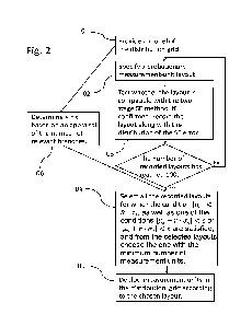
Figure 2 is a flowchart depicting an exemplary implementation of the
method of the invention for determining an optimal placement of measurement
units for estimating the state of a power distribution grid. The illustrated
flowchart
comprises six boxes. The first box (referenced 01) generally represents a
preliminary step of providing a model of the power distribution grid to which
the
method should apply. The complete model of a grid typically comprises the
grid's
admittance matrix containing the topology of the grid, as well as the
conductance
and susceptance of the branches connecting the nodes, and further comprises
the
nominal capacity of every branch as well as of the loads and generations at
every
node.
The second box (referenced 02) represents the task of specifying a
hypothetical monitoring infrastructure for the model of the power distribution
grid.
The hypothetical monitoring infrastructure comprises at least one randomly
placed
measurement unit. Any node of the power distribution grid that is equipped
with a
measurement unit according to the hypothetical monitoring infrastructure is
called
a "measuring node" of the hypothetical monitoring infrastructure.
The third box (referenced 03) represents the task of assessing
whether the placement of the at least one measurement unit of the hypothetical
monitoring infrastructure is compatible with the two-stage state estimation
(SE)
CA 03233527 2024- 3- 28
WO 2023/057856
PCT/IB2022/059216
8
method of the invention. The first stage of the state estimation method
consists in
implementing a Minimum Norm State Estimation for each scenario comprised in a
set of stochastic scenarios of the loads and generations in the power
distribution
grid. For each particular scenario, the Minimum Norm SE uses "measured data"
as
input. The "measured data" is actually simulated measured data supposed to
come from the nodes of the power distribution grid that are provided with
measurement units according to the hypothetical monitoring infrastructure. The
"measured data" are computed for each particular scenario of loads and
generations. In order for the placement of the at least one measurement unit
(i.e.
the hypothetical monitoring infrastructure) to be compatible with the two-
stage SE
method, the result of the first stage must be controllable.
The second stage of the state estimation method consists in
implementing a Weighted Least Square (WLS) SE for each scenario comprised in
the set of stochastic scenarios. The WLS SE uses the same measured data as the
Minimum Norm SE as input. Furthermore, the WLS SE also uses states estimated
to have non-zero values in the first stage as input. State variables estimated
by the
Minimum Norm SE for each scenario in the first stage, and used as input in the
second state, are called "estimeasurements" or "E/Ms" in the context of the
present two-stage state estimation method. In order for the placement of the
at
least one measurement unit to be compatible with the two-stage SE method, the
result of the second stage must be observable. The third box (box 03) further
provides that, if the placement of the at least one measurement unit of the
hypothetical monitoring infrastructure is compatible with the two-stage state
estimation method, one further computes the second stage state estimation
error.
If the means ps of the estimation error is smaller than A (i.e 1p21 < A, with
A G
and the standard deviation as is smaller than B (i.e. [c.j < , with BE
), the
means and the standard deviation of the error are recorded along with the
measurement-unit placement (to give an example, typical values for A and B are
CA 03233527 2024- 3- 28
WO 2023/057856
PCT/IB2022/059216
9
A = 0.15 and B = 0.60. These values are given here in p.u., or in other words
"per
unit").
The routine consisting in successively implementing the tasks
represented in boxes 02 and 03 is repeated until a predefined number of
placements (for example one hundred placements) have been recorded. Once the
predefined number of placements has been recorded, the method moves on to the
fourth box.
The fourth box (referenced 04) generally represents selecting the
measurement-unit placements for which the conditions 11.4õ. T .Ã7,.[ < E. and
<R 6, are both satisfied (where u,, is the means of the second stage state
estimation error, and 0-, is its standard deviation). According to the
invention R < 3.
Both the condition involving "r' and the condition involving "R" are required
by the
presently described particular implementation that invention. However, it is
important to note that either one, or both, of these the conditions can be
dispensed
with. Accordingly, neither one of them is present in each and every
implementation
of the method of the invention. The task represented by the fourth box further
comprises choosing from the selected measurement-unit placements, the
placement with the minimum number of measurement units.
The fifth box (referenced 05) represents the task of deploying the
measurement units in the physical distribution grid according to the chosen
placement.
The sixth box (referenced 06) generally represents the task of firstly
identifying the branches of the power distribution grid that are significantly
exposed
to the risk of congestion or inverse power flow, of secondly assessing the
percentage ( of these branches that should be monitored with high accuracy,
and
of thirdly determining the ratio r of the standard deviation (cr,,) over the
means (p,)
of a normal distribution, such that the percentage of cases in the normal
CA 03233527 2024- 3- 28
WO 2023/057856
PCT/IB2022/059216
distribution that are contained in a permittance having a width of no more
than
0s5 - LT, and that is centered at it,7 r = tr., , or in other words at zero,
is equal to C.
Provided that no pseudo-measurements are used, SE error may be
considered to be distributed normally with a statistical mean p and a variance
a2.
5 Furthermore, the error of the subset S, made up of the estimated state
variables
for the branches that are significantly exposed to congestion or inverse power
flow,
will also follow normal distribution of mean ,us and variance a-s2. If ps +
ras crosses
0, for r El, then at least C < ISI states in S are estimated with high
accuracy (low
error); e.g. if ISI=/00 and ,us + 1.25-as = 0 c (i.e. r=1.25), then about =9
states
10 have low SE error, because if we consider that a close vicinity of ps r
= 0
corresponds to the interval [ps + as, ps+ 1.5-as], it follows that 9.2% of all
samples
of the normal distribution are in the close vicinity of ys r
= 0 (refer to Figure
3A) (it should be noted that the same analysis also applies if ps - ras
crosses 0).
Inversely, if C states in S must be estimated accurately, an r may be selected
so
that, if ,us + ras crosses 0, then the interval [ps + as, ps + 1.5-as]
contains a
portion of ISI equal to C
It should be noted that the value of "r' depends on the width of the
interval (hereinafter the "permittance") that is considered to embody the
close
vicinity of pc +
= 0. For example, if instead of being equal to 0.5-as as
before, the permittance is equal to 0.25-as, and the number of states that
have to
be estimated accurately is still C=9, then the estimated value of "( will be
0.375,
because the interval [ps + 0.25-os, ps + 0.5-os] of a normal distribution
contains
9.1% of the cases (refer to Figure 3B). One will understand that the lower the
interval permittance, the smaller the value of "r'. Furthermore as p,s r = t3-
,; = a,
the smaller the value of "r", the smaller the value of ps. It follows that if
the interval
permittance is smaller, the selected placements will require a greater number
of
measurement units. On the other hand, if the permittance is substantially
greater
CA 03233527 2024- 3- 28
WO 2023/057856
PCT/IB2022/059216
11
than 0.5-as, the number of states that are estimated accurately will be
questionable.
Figure 4 is a flowchart illustrating in greater detail a particular
implementation of the routine represented by a loop containing boxes 02 and 03
of
Figure 2. The first box of Figure 4 (box 11) is identical to box 02 of Figure
2.
The second box of Figure 4 (box 12) consists in the task of obtaining
a set of stochastic scenarios for the loads and generations in the power
distribution grid. The obtained set should contain at least about 1000
different
scenarios for (i.e. operating conditions of) the loads and generations (i.e.
demand
loading, as well as Distributed Generation and Storage (DGS) if present). The
stochastic scenarios for the loads and generations can be obtained either from
simulations (for example by running a Monte Carlo) or from actual data (if
many
measured profiles of loads and generations in the power distribution grid are
available).
The third box of Figure 4 (box 13) consists in running a power flow
algorithm in order to simulate the power flow in the modelled distribution
grid for
each one of the operating scenarios contained in the sample that was obtained
during the previous step, and further to compute the state of the power
distribution
grid for each scenario. The values computed by the power flow algorithm for
voltages at measuring nodes of the hypothetical monitoring infrastructure, for
currents through branches that are incident on measuring nodes of the
hypothetical monitoring infrastructure, as well as for currents associated
with
power injections at measuring nodes of the hypothetical monitoring
infrastructure,
are referred to hereafter as "measured values", and the corresponding values
of
the active and reactive powers are also referred to as "measured values".
The fourth box of Figure 4 (box 14) consists in adding random noise
to the "measured values" obtained in the previous step. The added noise should
be representative of the accuracy level of the measurement units. For
instances,
for a measurement device with 99.9% accuracy, the added random noise can be
CA 03233527 2024- 3- 28
WO 2023/057856
PCT/IB2022/059216
12
calculated from a normal distribution with a mean value of 0 and standard
deviation of 0.1% of the "measured value".
The fifth box of Figure 4 (box 15) consists in using Minimum Norm to
identify an objective function for the states of the power distribution grid,
as well as
to estimate the grid state variables for each one of the operating scenarios
obtained in the second step. For each scenario, this Minimum Norm SE uses the
corresponding measured values obtained in the fourth step as input. As
previously
noted, the state estimation method of the invention is performed in two
stages,
first, a Minimum Norm formulation, followed by a Weighted Least Squares one.
One will therefore understand that the fifth box (box 15) corresponds to the
first
stage of the SE.
In the first stage, the SE problem can be formulated as the following
Minimum Norm optimization problem:
find min
subject to =
f = a
where is all grid state variables, i is the measured values, and the
model of power flow equations is given by f(i-).
According to an exemplary implementation that does not require
using PMUs, the method uses a known power flow approximation that is linear
for
a radial distribution grid when solved for the square of bus voltage
magnitudes
[18]. It should be understood however that the present invention does not
require
using a linear approximation. According to the above-mentioned exemplary
implementation, the first stage of the two-stage SE method of the invention is
defined as follows:
1st stage: min
s.t. = f;i2, fr = 4-77 = .450150'
CA 03233527 2024- 3- 28
WO 2023/057856
PCT/IB2022/059216
13
1;12 = ¨ 2Puro, ¨ 24'
ft;2 ¨ ¨
¨ ¨ 2 4iiiXs:j.
= c'52 ¨ u
= fl'i2real(11-0 +
Pf2trtiaR (KO.
= 1":?1` ertgYki)
=c2img() j
where V, p, q, r and x are the voltage magnitude, active and reactive power
flows,
line resistance and reactance, respectively, between buses i and j. Where,
beyond
the previously defined variables, Y, P and Q denote the DS admittance matrix,
active and reactive power injections, respectively, while values under hats
denote
measured values and those under tildes denote first stage estimated values of
state variables (hereinafter "estimeasurements" or "E/Ms").
The sixth box of Figure 4 (box 16) represents testing the optimization
problem defined in the previous step to assess whether it makes the power
distribution grid controllable. If the outcome of the test is negative, the
process
returns to the first box (box 11) as the previous version of the hypothetical
monitoring infrastructure is replaced with a new version. The placement of the
measurement units in the new version of the hypothetical monitoring
infrastructure
must be different from the placement of the measurement units in the previous
version. If the outcome of the test is positive, the process moves on to the
next
step (box 17).
The seventh box if Figure 4 (box 17) consists in using Weighted
Least Square to identify an objective function for the states of the power
distribution grid, as well as to estimate the grid state variables for each
one of the
operating scenarios obtained in box 12. For each scenario, this Weighted Least
Square SE uses the corresponding measured values and E/Ms obtained inbox 15
as input. The seventh box corresponds to the second stage of the SE.
CA 03233527 2024- 3- 28
WO 2023/057856
PCT/IB2022/059216
14
In the second stage, the SE problem can be formulated as the
following Weighted Least Square problem:
find: min:. ¨ x
Subject to f(i% x) =
where x is all grid state variables, is all grid state variables
calculated at stage 1, is the measurement values, and the model of
power flow equations is given by .1(37,,
According to an exemplary implementation that does not require
using PMUs, the second stage of the two-stage SE method of the invention is
defined as follows:
2nd stage: min (z Ay)' = IV (z ¨ Ay)
for y =
s.t. Ay
Tit2 -= WV17i2V/),p, = 417E4 =V13 (1)
Vi2V9i2V13 = .17,2 2p r. 28r
V3'2 = ft;72V17j-2V-3:1- ¨ 2-q
= (2)
T(r.2
= V72 ¨ ¨
= 1E2rea2frid p, = )
4 (3)
{vi= Viztriza) .." 17 j
= tirjeiVj (4)
Where, as in the first step, v, p, q, r and x are the voltage magnitude,
active and
reactive power flows, line resistance and reactance, respectively, between
buses i
and]; and Y, P and Q denote the DS admittance matrix, active and reactive
power
injections, respectively, while values under hats denote measured values and
those under tildes denote E/Ms. Variables without hats or tildes are the
second
stage estimated values of the state variables. For the case of voltage
magnitude,
the nominal voltage may be used as a kind of pseudo-measurement (P/M) (i.e. a
P/M of 1 p.u.), if neither a measured value nor an E/M is available.
CA 03233527 2024- 3- 28
WO 2023/057856
PCT/IB2022/059216
The eighth box of Figure 4 (box 18) consists in testing the
optimization problem defined in the previous step to assess whether it makes
the
power distribution grid observable. If the outcome of the test is negative,
the
process returns to the first box (box 11) as the previous version of the
hypothetical
5 monitoring infrastructure is replaced with a new version. The placement
of the
measurement units in the new version of the hypothetical monitoring
infrastructure
should be different from the placement of the measurement units in all
previous
versions. If the outcome of the test is positive, the process moves on to the
next
step (box 19).
10 The nineth box (box 19) represents firstly the task of
calculating the
second stage SE errors for a subset S of the estimated grid state variables
(according to some implementations, the subset S may be equal to the entire
set
of estimated grid state variables). The second stage SE errors can be
calculated
by comparing the grid state variables estimated in box 17 with the ones
previously
15 calculated in box 13. Secondly, box 19 also represents the task of the
recording
the placement of the measurement units in the current version of the
hypothetical
monitoring infrastructure, along with the means (Ps) and the standard
deviation
(as) of the calculated second stage SE errors for the subset S of the
estimated
grid state variables. One will understand that, in case where the subset S is
not
equal to the entire set of estimated grid state variables, the subset S should
comprise the estimated state variables that concern branches of the power
distribution grid that were identified earlier as being significantly exposed
to
congestion or inverse power flow. In the case of implementations of the method
that comprise a step of determining "(' (box 06 of Figure 2), the subset S can
be
made up of the branches of the power distribution grid that were identified as
being significantly exposed to congestion or inverse power flow in the course
of
determining
The routine illustrated in Figure 4 (comprising each of the boxes 11
to 19) is repeated a predetermined number of times (for example one hundred
CA 03233527 2024- 3- 28
WO 2023/057856
PCT/IB2022/059216
16
times), so that a predetermined number of measurement-unit placements are
recorded along with the values of the means and of the standard deviation of
the
SE errors associated with that particular measurement-unit placement.
Figure 5 is a flowchart depicting an alternative version of the
exemplary implementation of the method of the invention illustrated by the
flowchart of figure 4. The tasks represented by boxes 21 to 25 of Figure 5 can
be
identical to the boxes represented by boxes 11 to 15 of Figure 4. Furthermore,
boxes 28 and 30 of Figure 5 can be identical to boxes 17 and 19 of Figure 4. A
first difference between the flowcharts of Figures 4 and 5 concerns the effect
of
the controllability test represented by box 16 in Figure 4. Indeed, according
to
Figure 5, when the outcome of the controllability test is positive, the
illustrated
implementation returns to box 22 and adds an additional randomly placed
measurement unit to the hypothetical monitoring infrastructure, instead of
moving
on to the second stage of the SE method right away. When the outcome of the
controllability test is negative, on the other hand, the last added
measurement unit
is removed from the hypothetical monitoring infrastructure as indicated by box
27.
Removing the last added measurement unit makes the power distribution grid
controllable again. The implementation of the method then moves on to the
second stage of the SE method represented by box 28.
A second difference between the flowcharts of Figures 4 and 5
concerns what happens in the case where the outcome of the observability test
represented by box 18 (Figure 4) is negative. According to Figure 4, in this
case,
the process returns to box 11 as previously described, and the current version
of
hypothetical monitoring infrastructure is replaced by a new version. According
to
Figure 5, on the other hand, only one of the measurement units of the current
hypothetical monitoring infrastructure is removed and replaced by new randomly
placed measurement unit. According to a preferred version of the
implementation
illustrated by the flowchart of Figure 5, the measurement unit that is removed
and
CA 03233527 2024- 3- 28
WO 2023/057856
PCT/IB2022/059216
17
replaced by new randomly placed measurement unit is the remaining last added
measurement unit.
EXAMPLE
By way of example, we now describe how the method illustrated by
the flowchart of Figure 2 can be applied to the 20-bus medium voltage feeder
of
Figure 1. As previously explained, the method begins with the step of
providing a
model of the distribution grid (Box 01 of Figure 2). The model of the
distribution
grid of the present example comprises all the conductances and susceptances
listed in Table 1, as well as the nominal capacity of every branch. In the
present
example, each branch has a nominal capacity equal to 8MVA.
Measurements from all the T/Fs in this grid over a whole year period
in 10' detail are available (about 53000 entries per T/F). A power flow
algorithm is
executed to retrieve all operating data for every 10' interval. The retrieved
data
provides an objective way of identifying the branches of the power
distribution grid
that are the most exposed to congestion or reverse power flow. Indeed, these
branches are the ones through which pass the highest active and reactive power
flows (by absolute value). The identified active and reactive power flows are
p1-2
and qi-2 through branch 1-2, p2-3 and q2-3 through branch 2-3, and finally p3-
9 and
q3-9 through branch 3-9. The subset Sr comprises the state variables p1-2,
p2_1, p2-3,
p3-2, p3-9 and p9-3, and the subset So comprises the state variables qi-2, q2-
1, q2-3,
q3-2, q3-9 and q9-3. The highest active power flows (by absolute value) in the
power
distribution grid are p1-2, p2-3, p3-9 and the highest reactive power flows
(by
absolute value) in the power distribution grid are qi-2, q2-3, q3-9. The
number of
critical active sj and reactive [sc., power flows are therefore both
considered to
be equal to six (k=6).
As a complete profile is available for numerous operating scenarios
of the distribution grid, the power flow data of about 1000 different cases is
used to
CA 03233527 2024- 3- 28
WO 2023/057856
PCT/IB2022/059216
18
obtain a random sample of operating scenarios of the load, instead of using
the
results of a (Monte Carlo) simulation (Box 12 of Figure 4 and Box 22 of Figure
5).
Among all the recorded measurement-unit placements (box 03 of
Figure 2, box 19 of Figure 4 and box 30 of Figure 5), there were 107
placements
for which the maximum voltage magnitude estimate error is less than 1%, and
the
measurement errors for the subsets of state variables Sp & SQ meet the
conditions
Of Ps + ras crossing 0 at rO.6 (i.e. C=1). Table II presents 4 of these
measurement
placements with their ps and as for active and reactive power flows as well as
the
average and maximum voltage magnitude estimate errors.
Table II.
IzI a A V mean A Vmax Placement
cpo
Sp -0.01 0.07
4 0.08 0.16 {1 7, 9,
10}
SQ -0.14 0.54 ,
Sp 0.02
7 = 0.05 0.14 {1, 2, 7, 9,
14, 15, 17}
SQ -0.15 0.36
Sp 002 2
11 - . =6 0.04 0.10 {1, 5, 7, 9, 10, 11, 14, 17, 18, 19,
20}
SQ -0.01 0.67
17
Sp -0.01 0.07 003 009 {1, 2, 3, 4, 5, 6, 7, 8, 9, 10, 12, 13, 14,
.
SQ -0.01 0.05 . 16, 17, 18, 20}
Figure 6 shows an indicative output of an exemplary implementation
of the two-stage SE of the invention in one particular operating case of the
medium voltage feeder of figure 1. The x-axis in Figure 6 shows the 20 buses
of
the feeder, while the y-axis on the left shows the voltages in p.u. (per unit
of the
nominal voltage), and the y-axis on the right shows the error between
estimated
and actual values. The estimated voltage profile of every node is given in
continuous pink and the actual voltage profile is shown by a red-dashed line.
The
estimated and actual voltages should be read from y-axis on the left (errors
for the
estimated voltage are in the order of io-2). The values for the estimation
error for
every node are shown in dotted brown. These values should be read from the y-
CA 03233527 2024- 3- 28
WO 2023/057856
PCT/IB2022/059216
19
axis on the right. One will understand that voltage estimate errors are very
small,
i.e. less than 0.004 p.u. and that the error is even smaller for the nodes
closer to
the primary substation (slack node).
CA 03233527 2024- 3- 28
WO 2023/057856
PCT/IB2022/059216
REFERENCES
[1] I. Roytelman and S. Shahidehpour, "State estimation for electric power
distribution systems in quasi real-time conditions," IEEE Transactions on
5 Power Delivery, vol. 8, no. 4, pp. 2009-2015, 1993.
[2] C. Lu, J. Teng, and W.-H. Liu, "Distribution system state estimation,"
IEEE
Transactions on Power systems, vol. 10, no. 1, pp. 229-240, 1995.
[3] K. Li, "State estimation for power distribution system and measurement
impacts," IEEE Transactions on Power Systems, vol. 11, no. 2, pp. 911-
10 916, 1996.
[4] H. Wang and N. N. Schulz, "A revised branch current-based distribution
system state estimation algorithm and meter placement impact," IEEE
Transactions on Power Systems, vol. 19, no. 1, pp. 207-213, 2004.
[5] J. Wu, Y. He, and N. Jenkins, "A robust state estimator for medium
voltage
15 distribution networks," IEEE Transactions on Power Systems, vol. 28,
no. 2,
pp. 1008-1016, 2013.
[6] D. A. Naughton and G. T. Heydt, "A linear state estimation formulation
for
smart distribution systems," IEEE Transactions on Power Systems, vol. 28,
no. 2, pp. 1187-1195, 2012.
20 [7] M. C. de Almeida and L. F. Ochoa, "An improved three-phase AMB
distribution system state estimator," IEEE Transactions on Power Systems,
vol. 32, no. 2, pp. 1463-1473, 2016.
[8] S. Prasad and D. V. Kumar, "Trade-offs in PMU and IED deployment for
active distribution state estimation using multi-objective evolutionary
algorithm," IEEE Transactions on Instrumentation and Measurement, vol.
67, no. 6, pp. 1298-1307, 2018.
[9] A. S. Zamzam, X. Fu, and N. D. Sidiropoulos, "Data-driven learning-
based
optimization for distribution system state estimation," IEEE Transactions on
Power Systems, vol. 34, no. 6, pp. 4796-4805, 2019.
[10] J. Liu, J. Tang, F. Ponci, A. Monti, C. Muscas, and P. A. Pegoraro,
"Trade-
offs in PMU deployment for state estimation in active distribution grids,"
IEEE Transactions on Smart Grid, vol. 3, no. 2, pp. 915-924, 2012.
[11] J. Liu, F. Ponci, A. Monti, C. Muscas, P. A. Pegoraro, and
S. Sulis, "Optimal
meter placement for robust measurement systems in active distribution
grids," IEEE Transactions on Instrumentation and Measurement, vol. 63,
no. 5, pp. 1096-1105, 2014.
CA 03233527 2024- 3- 28
WO 2023/057856
PCT/IB2022/059216
21
[12] R. Singh, B. C. Pal, and R. B. Vinter, "Measurement placement in
distribution system state estimation," IEEE Transactions on Power
Systems, vol. 24, no. 2, pp. 668-675, 2009.
[13] J. A. Taylor, Convex optimization of power systems. Cambridge University
Press, 2015.
[14] A. von Meier, E. Stewart, A. McEachern, M. Andersen, and L. Mehrmanesh,
"Precision micro-synchrophasors for distribution systems: A summary of
applications," IEEE Transactions on Smart Grid, vol. 8, no. 6, pp. 2926-
2936, 2017.
to [15] A. Monticelli, "Electric power system state estimation,"
Proceedings of the
IEEE, vol. 88, no. 2, pp. 262-282, 2000.
[16] P. A. Pegoraro et al., "Bayesian approach for distribution system state
estimation with non-Gaussian uncertainty models," IEEE Transactions on
Instrumentation and Measurement, vol. 66, no. 11, pp. 2957-2966, 2017.
[17] K. Dehghanpour, Z. Wang, J. Wang, Y. Yuan, and F. Bu, "A survey on state
estimation techniques and challenges in smart distribution systems," IEEE
Transactions on Smart Grid, vol. 10, no. 2, pp. 2312-2322, 2018.
[18] L. W. Gan, S. H. Low, and leee, "Convex Relaxations and Linear
Approximation for Optimal Power Flow in Multiphase Radial Networks",
2014 Power System Computation Conference (Pscc), 2014.
CA 03233527 2024- 3- 28