Note: Descriptions are shown in the official language in which they were submitted.
1
METHOD AND APPARATUS FOR LITHOGRAPHY-BASED GENERATIVE
MANUFACTURING OF A THREE-DIMENSIONAL COMPONENT
The invention relates to a method for the lithography-based
generative production of a three-dimensional component, in
which a beam emitted by an electromagnetic radiation source
is focused onto a focal point within a material by means of
an optical imaging unit and the focal point is displaced by
means of a deflection unit arranged upstream of the optical
imaging unit in the beam direction, as a result of which a
volume element of the material located at the focal point
is each successively solidified by means of multiphoton
absorption.
The invention further relates to an apparatus for
lithography-based generative manufacturing of a three-
dimensional component.
A method for forming a component in which the
solidification of a photosensitive material is carried out
by means of multiphoton absorption is known, for example,
from DE 10111422 Al. For this purpose, a focused laser beam
is irradiated into the bath of the photosensitive material,
whereby the irradiation conditions for a multiphoton
absorption process triggering the solidification are only
fulfilled in the immediate vicinity of the focus, so that
the focus of the beam is guided to the points to be
solidified within the bath volume according to the
geometric data of the component to be produced.
A volume element of the material is solidified at the
respective focal point, whereby neighboring volume elements
adhere to each other and the component is built up by
CA 03233703 2024- 4- 2
2
successive solidification of neighboring volume elements.
The component can be built up in layers, i.e. the volume
elements of a first layer are solidified first before the
volume elements of the next layer are solidified.
Irradiation devices for multiphoton absorption methods
include an optical system for focusing a laser beam and a
deflection device for deflecting the laser beam. The
deflection device is designed to focus the beam
successively on focal points within the material that lie
in one and the same plane, preferably perpendicular to the
direction of beam incidence into the material. In an x,y,z
coordinate system, this plane is also called the x,y plane.
The solidified volume elements created by the beam
deflection in the x,y plane form a layer of the component.
To build up the next layer, the relative position of the
focusing optics relative to the component is changed in the
z-direction, which corresponds to the direction of
incidence of the at least one beam into the material and is
perpendicular to the x,y-plane. By adjusting the focusing
optics relative to the component, which is usually
motorized, the focal point is shifted to a new x,y plane,
which is spaced from the previous x,y plane in the z
direction by the desired layer thickness.
Structuring a suitable material using multiphoton
absorption offers the advantage of exceedingly high
structure resolution, with volume elements with minimum
structure sizes of up to 50nm x 50nm x 50nm being
achievable. However, due to the small focal point volume,
the throughput of such a method is very low, since, for
example, for a volume of 1 mm3, a total of more than 109
CA 03233703 2024- 4- 2
3
points must be irradiated. This leads to very long
construction times, which is the main reason for the low
industrial use of multiphoton absorption processes.
In order to increase the component throughput without
losing the possibility of a high structural resolution, it
has already been proposed to vary the volume of the focal
point at least once during the construction of the
component, so that the component is constructed from
solidified volume elements of different volumes. Due to the
variable volume of the focal point, high resolutions are
possible (with a small focal point volume). At the same
time, a high writing speed (measured in mm3/h) is achievable
(with a large focal point volume). Thus, by varying the
focal point volume, high resolution can be combined with
high throughput. The variation of the focal point volume
can be used, for example, in such a way that a large focal
point volume is used in the interior of the component to be
built up in order to increase the throughput, and a smaller
focal point volume is used on the surface of the component
in order to form the component surface with high
resolution. Increasing the focal point volume allows for
higher structuring throughput, since the volume of material
solidified in one irradiation instance is increased. To
maintain high resolution at high throughput, small focal
point volumes can be used for finer structures and
surfaces, and larger focal point volumes can be used for
coarse structures and/or to fill interior spaces. Methods
and devices for changing the focal point volume are
described in WO 2018/006108 Al.
The invention aims to further develop a method and a device
for the lithography-based generative production of a three-
CA 03233703 2024- 4- 2
4
dimensional component in such a way that the writing speed
(measured in mm3/h) is increased even further.
To solve this problem, the invention provides in a method
of the type mentioned above that the beam is split into a
plurality of beams by a beam splitter, each of which is
successively focused onto focal points within the material
by means of the deflection unit and the optical imaging
unit, a number of acousto-optic modulator modules
corresponding to the number of beams being provided, so
that an acousto-optic modulator module which diffracts the
beam is arranged in the beam path of each beam.
The invention thus enables parallel writing with a
plurality of beams, so that the writing speed is multiplied
accordingly by the number of beams. The beam splitter is
designed to split the beam into at least two beams. The
beam splitter is preferably designed to split the beam into
2, 4, 8, 16, 32 or 64 beams. Any other number of beams is
also possible, e.g. an odd number of beams.
Because an acousto-optic modulator module is arranged in
the beam path of each beam, each beam can be influenced
independently of the other beams, preferably in such a way
that the position of the focal point of the respective beam
can be adjusted independently of the focal points of the
other beams or that the radiation intensity of the
respective beam can be adjusted independently of the focal
points of the other beams.
Depending on the configuration of the acousto-optic
modulator modules, the focal point can be displaced in any
spatial direction. Preferably, at least one of the acousto-
CA 03233703 2024- 4- 2
5
optic modulator modules is controlled in order to shift the
focal point of the associated beam in a z-direction,
whereby the z-direction corresponds to a direction of
incidence of the respective beam into the material.
Alternatively or additionally, at least one of the acousto-
optic modulator modules can be controlled in order to shift
the focal point of the associated beam in an x and/or y
direction, the x and y directions corresponding to two
orthogonal directions in a plane perpendicular to the
direction of incidence of the respective beam.
By arranging at least one acousto-optic modulator in the
beam path of each beam, each focal point can be shifted
continuously and at high speed in the x, y and/or z
direction. This makes it possible to freely select the
position of a volume element and therefore also to arrange
volume elements outside the z-positions defined by the
layer plane in order to achieve optimum adaptation to the
surface shape to be achieved in each case. The shifting of
the focal point in the x, y and/or z direction does not
require any mechanical adjustment of the optical imaging
unit relative to the component and is therefore independent
of the change from a first to a next layer. In particular,
the focal point can be shifted without moving parts, but
solely due to the effect of the aforementioned acousto-
optic modulator module.
An acousto-optic modulator is an optical component that
influences the frequency and direction of propagation or
intensity of incident light. For this purpose, an optical
grating is created in a transparent solid using sound
waves, at which the light beam is diffracted. This can be
CA 03233703 2024- 4- 2
6
used in structures known as acousto-optic deflectors to
generate beam deflection, whereby the deflection angle
depends on the relative wavelengths of light and sound
waves in the transparent solid. The deflection angle can be
adjusted by changing the sound wave frequency. This can be
used for the fine adjustment of the focal point in the x
and/or y direction described above.
The displacement in the z-direction is achieved, for
example, by generating a sound wave in the acousto-optical
deflector, the frequency of which is periodically
modulated. By periodically varying the frequency of the
sound wave generated in the transparent solid, a so-called
"cylindrical lens effect" is formed in an acousto-optical
deflector, which focuses the incident light beam in the
same way as a cylindrical lens. Specific control of the
periodic frequency modulation allows the focal length of
the cylindrical lens and thus the divergence of the beam
emerging from the acousto-optic deflector to be changed.
The beam with the divergence set in this way is guided
through an imaging unit of the irradiation device, in which
the beam is irradiated into the material in a focused
manner by means of a lens. The focal point of the beam
introduced into the material varies here in the z-direction
as a function of the divergence.
A preferred design here provides that the frequency
modulation of the sound wave has a constant sound wave
frequency gradient. This favors the creation of the so-
called "cylindrical lens effect".
Preferably, it is further provided that the focal point is
displaced by a change in the (constant) sound wave
CA 03233703 2024- 4- 2
7
frequency gradient of the frequency modulation. The change
of the sound wave frequency gradient can be achieved, for
example, by changing the bandwidth of the frequency
modulation while keeping the period duration of the
periodic modulation constant. Alternatively, the bandwidth
can be kept constant and the change of the sound wave
frequency gradient can be caused by a change of the period
duration.
The fundamental frequency of the sound wave is preferably
50 MHz or more for a transparent solid made of e.g. Te02, in
particular > 100 MHz, especially 100-150 MHz. For example,
the fundamental frequency is modulated by at least 10%,
preferably 20-30%. In the case of a fundamental frequency
of, for example, 110 MHz, this is periodically modulated by
MHz, i.e. the bandwidth of the frequency modulation is
50 MHz and the frequency of the sound wave is therefore
periodically modulated between 85 MHz and 135 MHz. As
already mentioned, the change of the sound wave frequency
20 gradient determines the focal length of the cylindrical
lens, whereby the modulation frequency is preferably at
least 100 kHz, in particular 0.1-10 MHz.
Furthermore, an acousto-optic modulator module can also be
25 used to change the intensity of the beam introduced into
the material. The change can also involve reducing the
radiation intensity to zero so that the beams coming out of
the beam splitter can be switched on and off individually
as required. To adjust the radiation intensity, the
amplitude of the sound wave introduced into the acousto-
optic modulator is changed.
CA 03233703 2024- 4- 2
8
An acousto-optic modulator module comprises at least one
acousto-optic modulator, such as one, two or four acousto-
optic modulators. In the case of at least two acousto-optic
modulators, each modulator can be designed as a separate
component through which the respective beam passes in
succession. Alternatively, at least two acousto-optic
modulators can be functionally combined in a single
modulator component (so-called multichannel design), which
has a crystal with corresponding sound input for each
channel.
Preferably, at least two acousto-optic modulators arranged
one behind the other in the beam path are used in the
acousto-optic modulator modules, with the at least two
acousto-optic modulators preferably having a direction of
beam deflection that is essentially perpendicular to one
another or the same orientation of beam deflection. The
combination of two acousto-optic modulators, preferably
arranged directly behind each other and perpendicular to
each other, eliminates the astigmatism that would otherwise
occur with a single modulator. If two acousto-optic
modulators are arranged in one plane, the possible
adjustment path of the focal point in the x and y
directions is doubled. According to a further preferred
embodiment, four acousto-optic modulators arranged in
series can be provided, of which the first two modulators
form a first pair and the following two modulators form a
second pair. The modulators within a pair are each designed
with the same orientation of beam deflection and the
modulators of the first pair have a direction of beam
deflection that is perpendicular to the modulators of the
second pair.
CA 03233703 2024- 4- 2
9
While the shifting of the focal points by the acousto-
optical modulator modules is used for fine positioning of
the focal points, e.g. to solidify volume elements outside
the usual grid points (so-called "grayscale lithography"),
the writing beams are moved through the entire writing area
in the x and y directions by means of a deflection unit
separate from the acousto-optical modulator modules. In
this context, a preferred design provides for the beams to
be subjected to a joint deflection in the x and y
directions by means of the deflection unit downstream of
the acousto-optical modulator modules in the beam path, in
particular a galvanometer scanner. The deflection unit is
advantageously arranged in the beam path between the
acousto-optic modulator modules and the optical imaging
unit. For two-dimensional beam deflection, either a mirror
can be deflected in two directions or two orthogonally
pivotable mirrors can be set up close to each other, by
which the beam is reflected. It is also possible to arrange
a lens system, in particular a 4f arrangement, between the
mirrors so that the axis of rotation of the first mirror is
projected onto the second mirror, thereby avoiding
geometric imaging errors. The two mirrors can each be
driven by a galvanometer drive or electric motor. In any
case, it is essential that all beams that are generated by
the beam splitter and then each pass through an acousto-
optical modulator module are deflected with the aid of one
and the same deflection unit and then focused into the
material with one and the same optical imaging unit.
Preferably, the component is built up layer by layer with
layers extending in the x-y plane, whereby the change from
one layer to the next layer involves changing the relative
position of the optical imaging unit relative to the
CA 03233703 2024- 4- 2
10
component in the z direction. The mechanical adjustment of
the relative position of the optical imaging unit relative
to the component results in the coarse adjustment of the
focal points in the z-direction, namely the change from one
layer to the next. For the adjustment of intermediate
stages in the z-direction, i.e. for the fine positioning of
the focal point in the z-direction, the position of the
focal points is changed by means of the aforementioned
acousto-optic modulator modules.
Preferably, the focal point can be shifted in the z-
direction by means of the acousto-optic modulator modules
within the layer thickness of a layer. Several sub-layers
of volume elements arranged one above the other in the z-
direction can also be produced within one layer without
having to mechanically adjust the relative position of the
optical imaging unit relative to the component.
According to a preferred application of the invention, at
least one of the focal points is displaced in the z-
direction by means of the acousto-optic modulator modules
in order to form a curved outer contour of the component.
Alternatively or additionally, at least one of the focal
points can be displaced in the z-direction by means of the
acousto-optic modulator module in order to form an outer
contour of the component that is inclined relative to the
x,y-plane. The displacement of at least one of the focal
points in the z-direction can follow the surface shape by
positioning the focal point in the edge area of the
component at a distance from the surface of the component
to be produced that corresponds to the distance of the
imaginary center of the volume element to be solidified
from the outer surface of the volume element.
CA 03233703 2024- 4- 2
11
According to a preferred method the material is present on
a material carrier, such as in a trough, and the
irradiation of the material is carried out from below
through the material carrier, which is permeable to the
radiation at least in some areas. In this case, a build
platform can be positioned at a distance from the material
carrier and the component can be built up on the build
platform by solidifying material located between the build
platform and the material carrier. Alternatively, it is
also possible to irradiate the material from above.
In the context of the present invention, the construction
time can be considerably reduced if the layers located in
the interior of the component are built up with a high
layer thickness and therefore with volume elements having a
large volume and the edge areas are built up from volume
elements having a smaller volume and, in the edge areas,
the position of the volume elements is additionally
individually adjusted along the z-direction in order to
obtain a high structural resolution at the surface.
In a preferred method, the variation of the focal volume is
such that the volume ratio between the largest focal point
volume during the production of a component and the
smallest focal point volume is at least 2, preferably at
least 5. Preferably, it is provided that the change of the
focal point volume takes place in at least one, preferably
two, in particular three, spatial directions perpendicular
to each other.
The change in the focal point volume is preferably caused
by the deflection of the individual beams by the associated
CA 03233703 2024- 4- 2
12
acousto-optic modulator module in a direction transverse to
the direction of travel of the respective writing beam,
which is caused by the deflection unit, in particular the
galvanometer scanner. If the galvanometer scanner moves the
respective beam in the x-direction, for example, in order
to solidify volume elements lying one behind the other in
the x-direction, the associated acousto-optical modulator
module can be controlled in such a way that the beam is
moved back and forth at high speed transversely to it, e.g.
in the y-direction. The amplitude of the aforementioned
back and forth movement determines the extent of the volume
element. By changing the amplitude, the focal point volume
or the volume of the volume element to be solidified can be
varied. The back and forth movement takes place at a speed
that corresponds to at least 5 times, preferably at least
10 times, the speed in the direction of travel of the
writing beam, which is caused by the deflection unit, in
particular the galvanometer scanner, in the x-direction. It
is understood that the method just described for changing
the volume of the volume element to be solidified can be
carried out with the x and y directions reversed, so that
the deflection unit moves the writing beam or the focal
point further in the y direction and the rapid back and
forth movement by the acousto-optic modulator module is
transverse to it, e.g. in the x direction.
The principle of multiphoton absorption is used in the
context of the invention to initiate a photochemical
process in the photosensitive material bath. Multiphoton
absorption methods include, for example, 2-photon
absorption methods. As a result of the photochemical
reaction, there is a change in the material to at least one
other state, typically resulting in photopolymerization.
CA 03233703 2024- 4- 2
13
The principle of multiphoton absorption is based on the
fact that the aforementioned photochemical process takes
place only in those areas of the beam path where there is
sufficient photon density for multiphoton absorption. The
highest photon density occurs at the focal point of the
optical imaging system, so multiphoton absorption is
sufficiently likely to occur only at the focal point.
Outside the focal point, the photon density is lower, so
the probability of multiphoton absorption outside the focal
point is too low to cause an irreversible change in the
material by a photochemical reaction. The electromagnetic
radiation can pass through the material largely unhindered
in the wavelength used, and only at the focal point does an
interaction occur between photosensitive material and
electromagnetic radiation. The principle of multiphoton
absorption is described, for example, in Zipfel et al,
"Nonlinear magic: multiphoton microscopy in the
biosciences," NATURE BIOTECHNOLOGY VOLUME 21 NUMBER 11
NOVEMBER 2003.
The source of the electromagnetic radiation may preferably
be a collimated laser beam. The laser can emit one or more,
fixed or variable wavelengths. In particular, it is a
continuous or pulsed laser with pulse lengths in the
nanosecond, picosecond or femtosecond range. A pulsed
femtosecond laser offers the advantage that a lower average
power is required for multiphoton absorption.
Photosensitive material is defined as any material that is
flowable or solid under building conditions and that
changes to a second state by multiphoton absorption in the
focal point volume - for example, by polymerization. The
material change must be limited to the focal point volume
CA 03233703 2024- 4- 2
14
and its immediate surroundings. The change in substance
properties may be permanent and consist, for example, in a
change from a liquid to a solid state, but it may also be
temporary. Incidentally, a permanent change can also be
reversible or non-reversible. The change in material
properties does not necessarily have to be a complete
transition from one state to the other, but can also be
present as a mixed form of both states.
The power of the electromagnetic radiation and the exposure
time influence the quality of the produced component. By
adjusting the radiation power and/or the exposure time, the
volume of the focal point can be varied within a narrow
range. If the radiation power is too high, additional
processes occur that can lead to damage of the component.
If the radiation power is too low, no permanent material
property change can occur. For each photosensitive
material, there are therefore typical construction process
parameters that are associated with good component
properties. In the context of the invention, a component is
preferably manufactured with a constant radiation power
over the entire construction process.
According to a second aspect of the invention, an apparatus
is provided for the lithography-based generative production
of a three-dimensional component, in particular for
carrying out a method according to the first aspect of the
invention, comprising a material carrier for a solidifiable
material and an irradiation device which can be controlled
for the position-selective irradiation of the solidifiable
material with at least one beam, characterized in that the
irradiation device comprises a beam splitter for splitting
an input beam into a plurality of beams, a deflection unit
CA 03233703 2024- 4- 2
15
arranged downstream of the beam splitter in the beam path
and an optical imaging unit arranged downstream of the
deflection unit in order to focus each beam successively
onto focal points within the material, as a result of which
in each case a volume element of the material located at
the focal point can be solidified by means of multiphoton
absorption, a number of acousto-optic modulator modules
corresponding to the number of beams being provided, so
that an acousto-optic modulator module which comprises at
least one acousto-optic modulator is arranged in the beam
path of each beam.
Preferably, the acousto-optic modulator modules are
designed to shift the respective focal point in a z-
direction, whereby the z-direction corresponds to a
direction of incidence of the associated beam into the
material.
Preferably, the control of the at least one acousto-optic
modulator module comprises a frequency generator which is
designed for periodic modulation of the sound wave
frequency.
Preferably, it is provided here that the frequency
generator is designed to change the sound wave frequency
gradient.
It is also preferable that the acousto-optic modulator
modules are designed to shift the respective focal point in
an x and/or y direction, with the x and y directions
corresponding to two orthogonal directions in a plane
perpendicular to the direction of incidence of the
respective beam.
CA 03233703 2024- 4- 2
16
As already mentioned in connection with the method
according to the invention, it is advantageous if the
acousto-optic modulator modules each comprise at least two
acousto-optic modulators arranged one behind the other in
the beam path, the at least two acousto-optic modulators
preferably having a direction of their beam deflection that
is essentially perpendicular to one another or an identical
orientation of their beam deflection
Furthermore, the deflection unit can be arranged downstream
of the acousto-optical modulator modules in the beam path,
in particular formed by a galvanometer scanner, which is
designed to effect a joint displacement of the focal points
in an x-y plane running transverse to the z direction.
In particular, the irradiation device can be designed to
build up the component layer by layer with layers extending
in the x-y plane, with the change from one layer to the
next layer comprising the change in the relative position
of the optical imaging unit relative to the component in
the z direction.
The irradiation device is preferably designed in such a way
that the fine adjustment of the focal point in the z-
direction takes place within the layer thickness of a layer
by means of the acousto-optical modulator.
Furthermore, it can be provided that the material is
present on a material carrier, such as in a trough, and the
irradiation of the material is carried out from below
through the material carrier, which is permeable to the
radiation at least in certain areas.
CA 03233703 2024- 4- 2
17
The build platform is preferably positioned at a distance
from the material carrier and the component is built up on
the build platform by solidifying volume elements located
between the build platform and the material carrier.
It is advantageous if the volume of the focal point is
varied at least once during the construction of the
component, so that the component is constructed from
solidified volume elements of different volumes.
The imaging unit can be designed as an f-theta lens or
preferably consists of a microscopy objective and relay
optics in a 4f arrangement, whereby the deflection unit and
the objective are located in the focal plane of the
corresponding lenses.
The invention is explained in more detail below with
reference to schematic examples of embodiments shown in the
drawing. In this Fig. 1 shows a schematic representation of
a device according to the invention, Fig. 2, 3 and 4 a
detailed view of alternative designs of an acousto-optic
modulator module and Fig. 5 a schematic representation of
the focal points in the image field of the device during
the production of a component.
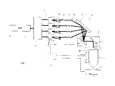
In Fig. 1, a carrier is labeled 1 on which a component is
to be mounted. The carrier is coated with a
photopolymerizable material 2 into which laser beams are
focused, each laser beam being focused successively on
focal points within the photopolymerizable material,
whereby a volume element of the material located at the
focal point is solidified by means of multiphoton
CA 03233703 2024- 4- 2
18
absorption. For this purpose, a laser beam is emitted from
a radiation source 3, passed through a pulse compressor 4
and split into a plurality of beams (in this case four
beams) in a beam splitter 5. The rays are now irradiated
into the material 2 by means of an irradiation device 6.
For this purpose, the irradiation device 6 comprises an
acousto-optical modulator unit 7, a deflecting mirror 8, a
galvanometer scanner 9 and an optical imaging unit 10
comprising an objective which introduces the laser beams
into the material 2 within a writing range.
The acousto-optic modulator unit 7 comprises a number of
acousto-optic modulator modules 11 corresponding to the
number of beams, of which at least one acousto-optic
modulator splits the respective beam into a zero-order beam
and a first-order beam. The zero-order beam is collected in
a beam trap 12. The first-order beam is directed via relay
lenses 13 and a deflector 14 onto the deflecting mirror 8,
which guides the beams into the deflection unit 9 (e.g. a
galvanometer scanner), in which the beams are successively
reflected by two mirrors 15. The mirrors 15 are driven to
swivel about axes of rotation that are orthogonal to each
other so that the beams can be deflected in both the x and
y directions. The two mirrors 15 can each be driven by a
galvanometer drive or electric motor. The beams emerging
from the deflection unit 9 preferably enter the lens 10 via
an optional relay lens system (not shown), which focuses
the beams into the photopolymerizable material as already
mentioned.
To build up the component layer by layer, volume elements
of one layer after the other are solidified in the
material. To build up a first layer, the laser beams are
CA 03233703 2024- 4- 2
19
focused one after the other on focal points arranged in the
focal plane of the lens 10 within the material 2. The joint
deflection of the beams in the x,y plane is carried out
with the aid of the deflection unit 9, whereby the writing
range is limited by the lens 10. To change to the next
plane, the lens 10 attached to a carrier 16 is moved in the
z-direction relative to the carrier 1 by the distance
between the layers, which corresponds to the layer
thickness. Alternatively, the carrier 1 can also be
adjusted relative to the fixed lens 10.
If the component to be produced is larger in the x and/or y
direction than the writing range of the lens 10,
substructures of the component are built up next to each
other (so-called stitching). For this purpose, the carrier
1 is arranged on a cross table, which can be moved in the x
and/or y direction relative to the irradiation device 6.
A control unit 17 is also provided, which controls the
acousto-optical modulator unit 7, the deflection unit 9,
the height adjuster 16 and the carrier 1 attached to the
cross table.
As shown in Fig. 2, an acousto-optic modulator module 11
can have two acousto-optic modulators 18 arranged one after
the other, whose direction of beam deflection coincides.
This has the effect that the deflection is twice as large
compared to a single acousto-optic modulator, and that the
deflection in the x, y and z directions can be controlled
independently of each other. This means that any point
within the available deflection range can be controlled and
fine adjustment of the focal point in the z-direction is
possible. The disadvantage of this arrangement is the
CA 03233703 2024- 4- 2
20
astigmatism caused by the cylindrical lens effect of the
acousto-optic modulator.
The acousto-optical modulators 11 each form a cylindrical
lens effect that depends on the sound wave frequency
gradient of the frequency modulation. The equivalent focal
length of the cylindrical lens n can be calculated as
follows:
Va 2
F1 = dF
A a
dt
where va is the acoustic propagation velocity in the
crystal, A is the wavelength of the laser beam, and dFaidtis
the acoustic wave frequency gradient in the crystal. In Te02
with a propagation speed of 4200 m/s at a laser wavelength
of 780 nm and traversing a bandwidth of 25 MHz (e.g.,
starting from a fundamental excitation frequency of 110
MHz) within 0.2 ps, the focal length of the acousto-optic
cylindrical lens is 90 mm. For an objective 4 with a focal
length of 9 mm and a 20x expansion, this results in a new
focal length of the entire system of
FObj Fl
Ftotal =
FObj+Fl
which corresponds to a displacement in the z-direction,
depending on the sign of the gradient, of 90 pm for the
parameters mentioned above. By changing the sound wave
frequency gradient, the z-position of the volume element
can be adjusted linearly and steplessly.
In the alternative embodiment according to Fig. 3, an
acousto-optic modulator module 11 comprises two acousto-
optic modulators 18 arranged one after the other, the
direction of beam deflection of which is perpendicular to
one another. With regard to the deflected first-order beam,
CA 03233703 2024- 4- 2
21
this acousto-optic modulator module 11 acts as a
cylindrical lens with an adjustable focal length, so that
the first-order beam has an adjustable divergence, which
allows the focal point to be adjusted in the x and y
directions, whereby the deflection direction of the
deflection unit can be freely selected. Furthermore, this
arrangement minimizes the resulting astigmatism, as two
mutually orthogonal cylindrical lenses are produced.
Fig. 4 shows a modified embodiment of the acousto-optic
modulator module 11, which has a first pair of acousto-
optic modulators 18 and a second pair of acousto-optic
modulators 18, between which relay lenses 19 are arranged
to ensure that the focal point at the input and output of
the acousto-optic modulator module 11 are arranged on the
same line. The two acousto-optic modulators 18 of each pair
have the same deflection direction. The direction of
deflection of the modulators of the first pair is
perpendicular to the direction of deflection of the
modulators of the second pair. This has the effect of
combining the advantages of the design shown in Fig. 2 with
those of the design shown in Fig. 3.
In Fig. 5, the writing range or image field 20 of the
optical imaging unit 10 is shown in the x and y directions,
whereby this is the section of the component that can be
built up between the optical imaging unit 10 and the
component to be built up without changing the relative
position in the x and y directions. Four focal points 21
can be seen, which are spaced apart so that four volume
elements of the component can be produced independently of
each other at the same time. The joint movement of the
focal points 21 in the x-direction takes place with the aid
CA 03233703 2024- 4- 2
22
of the deflection unit 9. The focal points 21 can also be
finely adjusted independently of each other in the x, y
and/or z direction by means of the respective acousto-optic
modulator module 11, starting from their current basic
position defined by the deflection unit 9. For example,
during the movement of the focal points in the x-direction
caused by the deflection unit 9, a fine adjustment can be
made in the z-direction in order to adapt the position of
volume elements to a curved or inclined component contour
relative to the coordinate directions, similar to
"grayscale lithography". Furthermore, during the movement
of the focal points in the x-direction caused by the
deflection unit 9, a fine adjustment can be made in the y-
direction in such a way that the laser beam is moved back
and forth at high speed in order to be able to adjust the
expansion of the volume element to be solidified in the y-
direction depending on the amplitude of the back and forth
movement.
CA 03233703 2024- 4- 2