Note: Descriptions are shown in the official language in which they were submitted.
WO 2023/065796
PCT/CN2022/113006
METHOD, SYSTEM, AND COMPUTER-READABLE MEDIUM FOR OPERATING AND
MONITORING THE CLEANING OF SAMPLE PROCESSING INSTRUMENTS
FIELD
[0001] The present disclosure relates to a method or system for operating and
cleaning a sample
processing instrument and a sample processing instrument including the system,
e.g., a flow
cytometer sorter or analyzer.
BACKGROUND
[0002] This section only provides background information related to the
present disclosure, which
is not necessarily prior art.
[0003] A sample processing instrument is usually configured to analyze a
liquid sample including
small suspended particles (e.g., biological particles such as extracellular
vesicles, non-biological
particles such as beads) or cells and/or to sort the particles or cells
therein. The sample processing
instrument generally processes multiple samples, and after a sample is
processed, it needs to be
cleaned to avoid inaccurate processing results for the next sample.
[0004] Some sample processing instruments are known to be cleaned with the use
of sheath fluid.
However, the sheath fluid is not necessarily suitable for all types of
samples. In other words, some
samples may not be cleaned well. If another cleaning agent is used to clean
the sample processing
instrument, it may be necessary to manually load the cleaning agent into the
sample processing
instrument, for example, in a semi-automatic loader. This may significantly
reduce the cleaning
efficiency.
[0005] In addition, it is not easy for users to accurately monitor and learn
the result of cleaning with
respect to traditional sample processing instruments. This is disadvantageous
for detection of
samples, especially, samples that contain small particles (e.g.,
nanoparticles) that are not easily
cleaned.
SUMMARY
[0006] This section provides a general summary of the disclosure and is not a
comprehensive
disclosure of its full scope or all of its features.
1
CA 03234205 2024- 4- 8
WO 2023/065796
PCT/CN2022/113006
[0007] An object of the present disclosure is to provide a method and system
capable of
automatically running and cleaning a sample processing instrument between
different samples
processed by the sample processing instrument.
[0008] Another object of the present application is to provide a method
capable of automatically
and continuously monitoring the cleaning of a sample processing instrument.
[0009] Yet another object of the present application is to provide a method
that is convenient for
users to operate and intuitively monitor the cleaning of the sample processing
instrument.
[0010] According to an aspect of the present application, there is provided a
method for operating
and monitoring the cleaning of a sample processing instrument, comprising
steps, performed by a
control device, of: directing a first sample through a flow cell in the sample
processing instrument,
wherein the first sample comprises first particles; processing the first
sample; cleaning the flow cell
of the sample processing instrument with a cleaning agent; measuring a
carryover amount in the
flow cell after the cleaning, wherein the carryover amount comprises a
measurement associated
with an amount of the first particles remaining in a measurement region of the
flow cell; comparing
the measured carryover amount against a predetermined target value, wherein
the target value
corresponds to a value indicative of a cleaning requirement; and determining,
based on the
comparison, whether the cleaning requirement is met.
[0011] In some embodiments according to the present application, the method
further comprises:
repeating the cleaning step when it is determined that the cleaning
requirement is not met; and
stopping a cleaning process when it is determined that the cleaning
requirement has been met or
when the number of cleaning reaches a maximum threshold.
[0012] In some embodiments according to the present application, the target
value is input by a user.
[0013] In some embodiments according to the present application, the cleaning
step comprises
selecting a cleaning agent from a plurality of cleaning agents configured to
clean the flow cell.
[0014] In some embodiments according to the present application, at least one
of the cleaning
agents comprises a sheath liquid.
[0015] In some embodiments according to the present application, the measuring
step comprises:
pumping the monitoring solution through the flow cell, and measuring light
scattered from within
the flow cell, wherein the measured light corresponds to the carryover amounts
in the flow cell.
[0016] In some embodiments according to the present application, the
monitoring solution is
different from the cleaning agent. In some embodiments, the monitoring
solution is water. In other
embodiments, the monitoring solution is a buffer.
[0017] In some embodiments according to the present application, the measuring
comprises:
measuring a count of carryovers and/or monitoring a volume of monitoring
solution.
2
CA 03234205 2024- 4- 8
WO 2023/065796
PCT/CN2022/113006
[0018] In some embodiments according to the present application, the carryover
amount may be a
count of carryover particles. In some embodiments the count of the carryover
particles and/or the
volume of the monitoring solution is the total count of carryover particles
and/or the total volume of
monitoring solution measured during a monitoring period, or a count of
carryover particles and/or a
volume of monitoring solution measured at predetermined intervals during the
monitoring period.
[0019] In some embodiments according to the present application, the method
further comprises
calculating, by the control device, based on the measured carryover amount, a
value representative
of relevance of the carryover amount to the monitoring solution (e.g., a value
of concentration of
the carryovers in the monitoring solution) and/or a value representative of
relevance of the
carryover amounts after cleaning and an amount of the first particles in a
sample before cleaning
(e.g., a value of ratio of the carryovers to the particles).
[0020] In some embodiments according to the present application, the method
further comprises
calculating a ratio of the carryover amount after the cleaning to an amount of
the first particles
detected in the first sample, or a ratio of a concentration of the carryovers
measured after cleaning
to a concentration of the first particles in the first sample.
[0021] In some embodiments according to the present application, the method
further comprises:
directing a second sample through the sample processing instrument following
the determination
that the cleaning requirement is met; and processing the second sample.
[0022] In some embodiments according to the present application, the second
sample is directed
through the sample processing instrument automatically by the control device
in response to the
determination that the cleaning requirement is met.
[0023] In some embodiments according to the present application, the first
particles comprise
biological nanoparticles.
[0024] In some embodiments according to the present application, the sample
processing
instrument is a flow cytometer, and wherein processing the first sample
comprises determining one
or more properties of the first particles in the first sample by directing an
optical beam toward the
flow cell and measuring light emitted or scattered from within the flow cell.
[0025] In some embodiments according to the present application, the method
further comprises
providing a user interface for being operated by a user and displaying
information to the user.
[0026] In some embodiments according to the present application, before the
cleaning, an operation
window is displayed on the user interface for a user to operate, and wherein
the operation window
comprises at least one of: options for selecting a process to be run, dialog
boxes for inputting
parameters and/or target values associated with the selected option, and
fields for setting cleaning
standards for cleaning/monitoring a flow cells after a particular sample is
processed(e.g., as
3
CA 03234205 2024- 4- 8
WO 2023/065796
PCT/CN2022/113006
described below with respect to FIG. 17, one or more particular samples may be
selected and
specific cleaning standards may be specified for the particular samples).
[0027] In some embodiments according to the present application, during the
cleaning or the
measuring, a status window is displayed on the user interface, and wherein a
running status is
displayed on the status window.
[0028] In some embodiments according to the present application, after the
measuring, a result
viewing window is displayed on the user interface, and wherein a running
result is displayed on the
result viewing window.
[0029] In some embodiments according to the present application, measured
carryover amount is
displayed in real time on the user interface.
[0030] In some embodiments according to the present application, control
buttons are provided on
the windows of the user interface for controlling a next activity.
[0031] According to another aspect of the present application, there is
provided a method for
operating and monitoring the cleaning of a sample processing instrument,
comprising, by a
computing system associated with the sample processing instrument: displaying,
on a user interface,
a menu comprising at least one next-activity element; displaying, on the user
interface, a parameter
setting element in response to a user selection of the at least one next-
activity element, wherein the
parameter setting element is configured to set a target carryover amount in a
flow cell of the sample
processing instrument; receiving a user input at the parameter setting
element, wherein the user
input specifies the target carryover amount; receiving carryover data
corresponding to a
measurement of particles present in a monitoring solution within the flow
cell; deriving an actual
carryover amount according to the received carryover data; and displaying, on
the user interface,
one or more monitoring elements representing the measured carryover amount,
the actual carryover
amount and/or the target carryover amount.
[0032] In some embodiments according to the present application, the method
further comprises:
detennining a cleaning level by comparing the actual carryover amount with the
target carryover
amount; and displaying, on the user interface, the cleaning level. The
cleaning level comprises a
first level indicating that a cleaning requirement is met and a second level
indicating that the
cleaning requirement is not met.
[0033] In some embodiments according to the present application, the method
further comprises,
when the second level is determined, repeating a cleaning cycle and then a
monitoring cycle until
maximum cleaning cycles are reached. Receiving the user input comprises
inputting parameters
associated with the cleaning cycle and the monitoring cycle at the parameter
setting element, and
wherein the parameters comprise the maximum cleaning cycles.
4
CA 03234205 2024- 4- 8
WO 2023/065796
PCT/CN2022/113006
[0034] In some embodiments according to the present application, the method
further comprises
displaying, on the user interface, status of the cleaning cycle and the
monitoring cycle.
[0035] In some embodiments according to the present application, the status of
the cleaning cycle
and the monitoring cycle comprises running process of the cleaning cycle, the
number of the
cleaning cycle which is performing, and running process of the monitoring
cycle.
[0036] In some embodiments according to the present application, the
monitoring elements
comprise a graph showing the measured carryover data.
[0037] In some embodiments according to the present application, the graph
comprises a histogram,
a scatter dot plot, a density plot, a pseudocolor plot, or a contour plot.
[0038] In some embodiments according to the present application, the graph
shows carryover signal
intensity vs carryover count
[0039] In some embodiments according to the present application, the parameter
setting element is
further configured to set a cleaning standard for cleaning/monitoring a flow
cells after a particular
sample is processed (e.g., as described below with respect to FIG. 17, one or
more particular
samples may be selected and specific cleaning standards may be specified for
cleaning the
particular samples).
[0040] In some embodiments according to the present application, the parameter
setting element
comprises a dialog box, a text field, a slider element, a dropdown list,
and/or a radio button.
[0041] In some embodiments according to the present application, the method
further comprises:
displaying, on the user interface, a setting-applicable-sample element in
response to a user selection
of the at least one next-activity element, wherein the setting-applicable-
sample element is
configured to specify samples to be monitored with the same user input at the
parameter setting
element; and receiving at the setting-applicable-sample element a user input
to specify the samples
to which the same user input at the parameter setting element is applied.
[0042] In some embodiments according to the present application, each of the
actual carryover
amount and the target carryover amount is showed in text, in a graph and or in
a table.
[0043] In some embodiments according to the present application, the actual
carryover amount and
the target carryover amount are showed in a same graph or table.
[0044] In some embodiments according to the present application, the method
further comprises:
storing monitoring data of each sample; and displaying, on the user interface,
the monitoring data of
the one or more samples in response to a user request for one or more samples
by the at least one
next-activity element.
[0045] In some embodiments according to the present application, the target
carryover amount
comprises at least one of a target carryover count, a target carryover rate, a
target carryover
5
CA 03234205 2024- 4- 8
WO 2023/065796
PCT/CN2022/113006
concentration and a target percentage of carryover concentration; and the
actual carryover amount
accordingly comprises at least one of an actual carryover count, an actual
carryover rate, an actual
carryover concentration and an actual percentage of carryover concentration.
[0046] In some embodiments according to the present application, the method
further comprises
displaying, on the user interface, control elements for starting, stopping,
interrupting, cancelling,
repeating the method or a step of the method.
[0047] In some embodiments according to the present application, the control
elements comprise
control buttons.
[0048] According to an aspect of the present application, there is provided a
system for operating
and monitoring the cleaning of a sample processing instrument, comprising: a
fluid pipeline
communicating fluid sources to a flow cell of the sample processing
instrument; a pump arranged in
the fluid pipeline; and a control device. The control device is configured to:
direct a first sample
through the flow cell in the sample processing instrument, wherein the first
sample comprises first
particles; process the first sample; control the pump to pump a cleaning agent
through the fluid
pipeline for cleaning the flow cell, and pump a monitoring solution through
the fluid pipeline;
measure a carryover amount in the cleaned flow cell, wherein the carryover
amount comprises a
measurement associated with an amount of the first particles remaining in a
measurement region of
the flow cell; compare the measured carryover amount against a predetermined
target value,
wherein the target value corresponds to a value indicative of a cleaning
requirement; and determine,
based on the comparison, whether the cleaning requirement is met.
[0049] In some embodiments according to the present application, the control
device is further
configured to: repeatedly clean the flow cell when it is determined that the
cleaning requirement is
not met; and stop a cleaning process when it is determined that the cleaning
requirement has been
met or when the number of cleaning reaches a maximum threshold.
[0050] In some embodiments according to the present application, the system
further comprises a
switching device, wherein the switching device is configured to enable the
pump to be in fluid
communication selectively with a sample needle fitted in the flow cell or a
sample source of the
fluid sources.
[0051] In some embodiments according to the present application, the switching
device comprises a
three-way valve including a first port connected to the pump, a second port
connected to the sample
needle and a third port connected to the sample source, and wherein the three-
way valve is switched
between a first position allowing the pump to communicate with the sample
needle and a second
position allowing the pump to communicate with the sample source.
6
CA 03234205 2024- 4- 8
WO 2023/065796
PCT/CN2022/113006
[0052] In some embodiments according to the present application, the pump is
communicated with
at least two cleaning agents.
[0053] In some embodiments according to the present application, the at least
two cleaning agents
include sheath fluid.
[0054] In some embodiments according to the present application, the pump
includes a first pump
For pumping the sheath fluid and a second pump for selectively pumping the
other cleaning agent
and the monitoring solution.
[0055] In some embodiments according to the present application, the
monitoring solution is water.
In other embodiments, the monitoring solution is a buffer.
[0056] According to another aspect of the present application, there is
provided a sample
processing instrument comprising the cleaning system described above
[0057] According to another aspect of the present application, there is
provided a computer-
readable medium on which a program is stored. The program is executed by a
processor of a control
device (e.g., on an associated personal computing device, on a dedicated
device, etc.) to implement
the method described above.
[0058] The above and other purposes, features and advantages of the present
disclosure are fully
understood through the detailed description and the drawings given for
describing rather than
limiting the present disclosure.
BRIEF DESCRIPTION OF THE DRAWINGS
[0059] The features and advantages of one or more embodiments of the present
disclosure will
become more readily understood from the following description with reference
to the
accompanying drawings in which:
[0060] FIG. 1 is a functional block diagram of the sample processing
instrument;
[0061] FIG. 2 is a schematic diagram of a part of a system according to an
embodiment of the
present application,
[0062] FIG. 3 is a schematic diagram showing the sampling process of the
system of FIG. 2;
[0063] FIGs. 4 to 6 are schematic diagrams showing that the system of FIG. 2
performs cleaning
with a cleaning agent other than the sheath liquid;
[0064] FIGs. 7 to 9 are schematic diagrams showing that the system of FIG. 2
performs cleaning
with sheath fluid,
[0065] FIG. 10 is a schematic diagram of a part of a system according to
another embodiment of
the present application;
7
CA 03234205 2024- 4- 8
WO 2023/065796
PCT/CN2022/113006
[0066] FIG. 11 is a schematic diagram of a part of a system according to yet
another embodiment
of the present application;
[0067] FIG. 12 is a schematic flowchart of a method for cleaning a sample
processing instrument
according to an embodiment of the present application;
[0068] FIG. 13 is a schematic flowchart of a method for cleaning a sample
processing instrument
according to another embodiment of the present application;
[0069] FIG. 14 is a schematic diagram of a user interface for monitoring
cleaning of a sample
processing instrument according to an embodiment of the present application;
[0070] FIG. 15 is a schematic diagram of an example of a menu of the user
interface;
[0071] FIG. 16 is a schematic diagram of an example of a parameter setting
element of the user
interface;
[0072] FIG. 17 is a schematic diagram of an example of a setting-applicable-
sample elements of the
user interface;
[0073] FIGs. 18A to 18E are schematic diagrams of various examples of a
monitoring element of
the user interface;
[0074] FIG. 19 is a schematic diagram of an example of a historical data
viewing element; and
[0075] FIG. 20 is a schematic diagram of a cleaning/monitoring user interface
integrated in the
sample processing user interface according to another embodiment of the
present disclosure.
DETAILED DESCRIPTION OF THE EMBODIMENTS
[0076] The present application is described in detail hereinafter by means of
exemplary
embodiments with reference to the accompanying drawings. In the several
drawings, similar
reference numerals indicate similar parts and components. The following
detailed description of the
present application is for explanation only and is by no means intended to
limit the present
application and the applications or usages thereof. The embodiments described
in this specification
are not exhaustive, but are only some of a number of possible embodiments. The
exemplary
embodiments may be implemented in many different forms, and should not be
construed as limiting
the scope of the present application. In some exemplary embodiments, well-
known processes, well-
known device structures, and well-known technologies may not be described in
detail.
[0077] Before at least one embodiment of the present application is explained
in detail, it is to be
understood that the present application is not limited in its application to
the details of construction
and the arrangement of the components set forth in the following description
or illustrated in the
drawings. The invention is applicable to other embodiments that may be
practiced or carried out in
8
CA 03234205 2024- 4- 8
WO 2023/065796
PCT/CN2022/113006
various ways as well as to combinations of the disclosed embodiments. In
addition, it is to be
understood that the phraseology and terminology employed herein are for the
purpose of description
and should not be regarded as limiting.
[0078] Unless specifically stated otherwise, as apparent from the following
discussions, it is
appreciated that throughout the specification discussions utilizing terms such
as "controlling-,
"processing", "calculating", "determining", "deriving" or the like, refer to
the action and/or
processes of a computer or computing system, or similar electronic computing
device, that
manipulates and/or transforms data represented as physical, such as
electronic, quantities within the
computing system's registers and/or memories into other data similarly
represented as physical
quantities within the computing system's memories, registers or other such
information storage,
transmission or display devices
[0079] The sample processing instrument according to the present disclosure
will be described by
taking a flow cytometer as an example. Flow cytometers are used to detect
particles in a sample to
determine one or more characteristics of the particles. However, it should be
understood that the
sample processing instrument according to the present disclosure is not
limited to a flow cytometer,
and may be any other suitable instrument for processing biological samples or
non-biological
samples. In some embodiments, the sample processing instrument may be a cell
or particle sorter.
[0080] The sample processing instrument according to the present disclosure is
suitable for
automatically performing the cleaning process between processing different
samples, for
automatically performing the cleaning process using different cleaning agents,
and for automatically
performing the monitoring process of measuring the cleaning result after the
cleaning process. The
system may additionally automatically determine the next action according to
the measurement
result. Additionally, the system may provide an interface to a user to enable
to user to easily operate
and intuitively observe the monitoring and cleaning process. The main
functional parts of the
sample processing instrument 1 will be described below with reference to FIG.
1. The sample
processed (for example, analyzed or sorted) by the sample processing
instrument 1 may include
biological particles such as exosomes or extracellular vesicles or non-
biological particles such as
beads. The disclosed system is optimized for detecting and measuring particles
at the nano-level
(e.g., nanoparticles, nanobeads, exosomes), but the disclosed system can also
be used for larger
particles.
[0081] FIG. 1 is a functional block diagram of the sample processing
instrument 1. As shown in
FIG. 1, the sample processing instrument 1 includes fluidics components 10, a
flow cell 20, a
sample processing unit 30 and a control unit 40.
9
CA 03234205 2024- 4- 8
WO 2023/065796
PCT/CN2022/113006
[0082] The fluidics components 10 are configured to supply various fluids to
the flow cell 20 and to
discharge the fluid out of the flow cell 20. The fluids described herein may
include samples to be
analyzed, sorted or otherwise processed, sheath fluid, cleaning agents, waste
fluids, and the like.
The fluidics components 10 may include various pumps, valves, pressure
regulating devices,
sensors, etc., for delivering fluid or discharging fluid.
[0083] Various fluids, particularly samples and sheath fluid are delivered to
the flow cell 20.
Referring to FIG. 2, the flow cell 20 includes two opposite sheath ports 21
and 22, and the sheath
fluid is delivered to the chamber 25 of the flow cell 20 through the sheath
ports 21 and 22. The flow
cell 20 further includes a sample needle 23 disposed therein, and the sample
is transported into the
chamber 25 through the sample needle 23. In the chamber 25, the sample is
wrapped in sheath fluid
and then flows through the cuvette 26 for processing. The cuvette 26 forms the
processing area of
the sample. For example, the optical detection device focuses the light beam
in the processing area
of the cuvette 26. in case that the particles in the sample pass through the
processing area of the
cuvette 26, the characteristics of the particles are determined by measuring
the light scattered or
emitted from the particles.
[0084] The sample processing unit 30 processes the sample wrapped in the
sheath fluid flowing
through the cuvette 26. For example, the sample processing unit 30 may measure
characteristics of
particles/cells in the sample and quantify the particles/cells having
particular characteristics, and/or
the sample processing unit 30 may sort particles/cells in the sample based on
their characteristics.
The sample processing unit 30 may include various optical devices, electrical
devices, and/or
mechanical devices according to the aim of sample processing.
[0085] The control unit 40 controls the operation of the entire sample
processing instrument 1. The
various functions, actions, or steps of the various systems, devices,
components, or methods of the
sample processing instrument according to the present application are
controlled by the control unit
40. The control unit 40 will be described in detail below.
[0086] An example of fluidics components according to an embodiment of the
present application
will be described below with reference to FIGs. 2 to 9 showing a part of a
system 100, which
includes fluidics for controlling flow of different fluids. As described
above, the fluidic system 100
is used to supply various fluids to the flow cell 20 and to discharge the
fluid out of the flow cell 20.
To this end, the fluidic system100 includes fluid pipelines connecting various
fluid sources to the
flow cell 20.
100871 These fluid sources may include a sample source 101, a sheath source
(not shown), a waste
reservoir, and other solution sources The sample source 101 is used to supply
samples Generally,
the sample source 101 includes multiple sample containers containing different
samples, for
CA 03234205 2024- 4- 8
WO 2023/065796
PCT/CN2022/113006
example, a well plate, a test tube, and the like. The sheath fluid is stored
in the sheath source.
Sheath liquid is the matrix liquid that helps the sample flow to be detected
normally, and may
function to wrap around the sample flow and keep it in the center of the
nozzle to ensure the
accuracy of detection while preventing particles in the sample flow from
approaching the nozzle
wall and blocking the nozzle. In addition, the sheath fluid may also be used
as a cleaning agent for
cleaning the sample processing instrument (especially, the flow cell and the
fluid pipelines). Other
solution sources include a fluid container 103 storing other cleaning agents
(for example, water or
another special cleaning solution) rather than the sheath fluid, and a
separate container (not shown)
storing a monitoring solution (for example, water or a buffer) for measuring
the cleaning result of
the sample processing instrument. The waste reservoir is used to collect the
waste liquid after
sample processing and cleaning of the sample processing instrument
[0088] Referring to FIG. 2, the fluid pipeline includes sample pipelines 111,
112 and 113 that
communicate the sample source 101 to the sample needle 23, a sheath pipeline
117 for
communicating a sheath source (not shown) to the sheath ports 21 and 22 of the
flow cell 20; a
waste pipeline 116 for communicating the flow cell 20 to a waste reservoir
(not shown); sheath
cleaning pipelines 153 and 154 for conveying sheath fluid for cleaning, and
cleaning agent pipelines
142 and 144 for conveying a cleaning agent for cleaning.
[0089] Various pumps for pumping various fluids may be provided in the fluid
pipeline. In the
example shown in FIG. 2, there is a sample pump 121 for pumping samples, a
sheath pump 125 for
pumping sheath liquid for cleaning, and a cleaning pump 123 for pumping a
cleaning agent. In the
example of FIG. 2, the sample pump 121, the sheath pump 125, and the cleaning
pump 123 are all
piston pumps. However, it should be understood that the systems disclosed in
the present
application are not limited to the specific examples shown in the drawings, as
long as it can realize
the functions described herein. For example, the type of the pump may be
varied. In another
embodiment shown in FIG 10, the sheath pump 125 and the cleaning pump 123 may
be other types
of pumps such as peristaltic pumps. Similarly, the sample pump 121 may also
adopt any other
suitable type of pump, for example, a peristaltic pump. In some embodiments,
the number of pumps
may be changed. In the example shown in FIG. 11, the sheath pump is omitted.
[0090] Various switching devices may be provided in the fluid pipeline, for
example, for switching
the flowing direction of the fluid or for controlling the on-off state of the
fluid. The switching
device may include various types of valves. As shown in FIG. 2, the switching
device includes
three-way valves 131 and 132 and on-off valves 141, 151 and 152.
[0091] The three-way valve 132 is configured to selectively communicate the
sample pipelines 111
to 113 with different pumps (for example, the sample pump 121 or the cleaning
pump 123) to suck
11
CA 03234205 2024- 4- 8
WO 2023/065796
PCT/CN2022/113006
or pump different fluids (for example, the sample or the cleaning agent) to
the flow cell 20 or the
sample source 101. In the example of FIG. 2, the three-way valve 132 includes
a first port 1321
connected to the sample pipeline 113, a second port 1322 connected to the
sample pump 121, and a
third port 1323 connected to the cleaning pump 123. In case that the first
port 1321 is switched to
communicate with the second port 1322, the sample pump 121 is allowed to suck
a sample from the
sample source 101 when the sample pipeline 113 is connected to the sample
pipeline 111 or pump a
Fluid (e.g., a sample or sheath fluid) to the flow cell 20 when the sample
pipeline 113 is connected
to the sample pipeline 112. That is, the system may allow the sample pump 121
to suck a sample
from the sample source 101 by switching the valve 132 to connect the sample
pump 121 to the
sample pipeline 113 and by switching the valve 131 to connect the sample
pipeline 113 to the
sample pipeline 111 (the sample or sheath fluid may alternatively be sent to
the flow cell 20 by
switching the valve 131 to connect the sample pipeline 113 to the sample
pipeline 112). The system
may allow the cleaning pump 123 to suck the cleaning agent from the fluid
container 103 and pump
it to the flow cell 20 by switching the valve 132 to connect the cleaning
pipeline 144 to the sample
pipeline 113 and by switching the valve 131 to connect the sample pipeline 113
to the sample
pipeline 112 (the cleaning agent may alternatively be sent to the sample
source 101 by switching
the valve 131 to connect the sample pipeline 113 to the sample pipeline 111).
[0092] The three-way valve 131 is configured to selectively communicate a pump
(e.g., the sample
pump 121 or the cleaning pump 123) with the sample source 101 or the flow cell
20 to selectively
suck or pump fluid (e.g., the sample or the cleaning agent) to the flow cell
20 or the sample source
101. In the example of FIG. 2, the three-way valve 131 is provided between the
sample pipelines
111, 112 and 113 for selectively communicating the sample pipeline 113 with
the sample pipeline
111 or the sample pipeline 112. The three-way valve 131 has a first port 1311
connected to the
sample pump 121 or the cleaning pump 123 via the three-way valve 132, a second
port 1312
connected to the sample needle 23, and a third port 1313 connected to the
sample source 101. The
system may allow the fluid in the sample pipeline 113 (for example, the sample
pumped by the
sample pump 121 or the cleaning agent pumped by the cleaning pump 123) to be
conveyed into the
Flow cell 20 by switching the valve 131 to connect the sample pipeline 113 to
the sample pipeline
112, or alternatively allow fluid to be sucked from/pump into the sample
source 101 by switching
the valve 131 to connect the sample pipeline 113 to the sample pipeline 111
[0093] By the three-way valves 131 and 132, it is possible to selectively pump
the sample to the
flow cell 20 to, for example, analyze the sample, or pump the cleaning agent
to the sample source
101 or the flow cell 20 to clean the sample pipelines 111 to 113 or the flow
cell 20.
12
CA 03234205 2024- 4- 8
WO 2023/065796
PCT/CN2022/113006
[0094] The cleaning pump 123 is connected to the third port 1323 of the three-
way valve 132 via a
cleaning agent pipeline 144, and is connected to the fluid container 103 via a
cleaning agent
pipeline 142. An on-off valve 141 may be provided in the cleaning agent
pipeline 142 to control the
on-off state of the cleaning agent pipeline 142. In case of sucking the
cleaning agent, the on-off
valve 141 is in a closed state to allow communication of the cleaning agent
pipeline 142. In case of
no need to suck the cleaning agent, the on-off valve 141 is in an open state
to interrupt the
communication of the cleaning agent pipeline 142.
[0095] The sheath pump 125 is arranged between the sheath pipeline 117
connected to the sheath
source and the sample pump 121 to deliver the sheath fluid to the sample
source 101 or the flow cell
20 via the sample pump 121, so as to clean the sample pipelines 111-113 or the
flow cell 20 with
the sheath fluid_ The sheath pump 125 is connected to the sheath pipeline 117
(or the sheath source)
via the sheath cleaning pipeline 153, and is connected to the sample pump 121
via the sheath
cleaning pipeline 154. An on-off valve 151 may be provided in the sheath
cleaning pipeline 153 to
control the on-off state of the sheath cleaning pipeline 153. In case that the
sheath fluid is sucked
for cleaning, the on-off valve 151 is in a closed (i.e., on) state to allow
communication of the sheath
cleaning pipeline 153 In case of no need to suck the sheath fluid, the on-off
valve 151 is in an open
(i.e., off) state to interrupt the communication of the sheath cleaning
pipeline 153. Furthermore, an
on-off valve 152 may be provided in the sheath cleaning pipeline 154 to
control the on-off state of
the sheath cleaning pipeline 154. In case of pumping the sheath fluid, the on-
off valve 152 is in a
closed (i.e., on) state to allow the communication of the sheath cleaning
pipeline 154. In case of no
need to pump the sheath fluid, the on-off valve 152 is in an open (i.e., off)
state to interrupt the
communication of the sheath cleaning pipeline 154.
[0096] It should be understood that the system according to the present
application is not limited to
the specific example shown in FIG. 2, but may be changed according to actual
requirements. For
example, in the system 200 shown in FIG. 10, the sheath pump 225 and the
cleaning pump 223 may
be peristaltic pumps, and accordingly, on-off valves may be omitted in the
sheath cleaning pipelines
253 and 254 and the cleaning agent pipeline 142. In the system 300 shown in
FIG. 11, the sheath
pump is omitted, and instead, only an on-off valve 351 is provided in the
sheath cleaning pipeline
353 between the sheath pipeline 317 (or the sheath source) and the sample pump
321. It should be
understood that the system according to the present application is not limited
to having the
components described above. For example, it may also have a filter (for
example, a filter 119 for
filtering sheath fluid as shown in FIG. 2), a sensor for sensing temperature
or pressure, a regulator
for adjusting temperature or pressure, and the like
13
CA 03234205 2024- 4- 8
WO 2023/065796
PCT/CN2022/113006
[0097] The process of conveying a sample through the fluidic system 100 during
sample processing
will be described below with reference to FIGs. 2 and 3.
[0098] As shown in FIG. 2, when a sample is to be processed, the three-way
valve 132 is switched
such that the sample pump 121 is connected to the sample pipeline 113, and the
three-way valve
131 is switched such that the sample pipeline 113 is connected to the sample
pipeline 111, whereby
the sample is sucked from the sample source 101 into the sample pipeline 113
by the sample pump
121 (for example, the piston of the sample pump 121 moves downward).
[0099] Then, as shown in FIG. 3, the three-way valve 131 is switched such that
the sample pipeline
113 is connected to the sample pipeline 112, and the sample in the sample
pipeline 113 is pumped
into the flow cell 20 by the sample pump 121 (for example, the piston of the
sample pump 121
moves upward) for processing (for example, detection or sorting, etc.).
[0100] During the sample processing, the sample pump 121 is always connected
to the sample
pipeline 113, and the three-way valve 131 is repeatedly switched between the
second port 1312 and
the third port 1313 to repeatedly perform the processes of sucking and pumping
samples until the
sample processing is finished.
[0101] The process of cleaning the sample pipelines 111 to 113 and the flow
cell 20 by the fluidic
system 100 using the cleaning agent will be described below with reference to
FIGs. 4 and 6.
[0102] As shown in FIG. 4, when the sample processing instrument is to be
cleaned with the
cleaning agent, the on-off valve 141 is closed to communicate the cleaning
agent pipeline 142,
thereby allowing the cleaning pump 123 to suck the cleaning agent from the
fluid container 103.
[0103] As shown in FIG. 5, the on-off valve 141 is switched to an open state,
and the three-way
valve 132 is switched such that the cleaning agent pipeline 144 is connected
to the sample pipeline
113 to pump the cleaning agent into the sample pipeline 113. At this moment,
the three-way valve
131 may be in a state where the sample pipeline 113 is connected to either of
the sample
pipeline112 and the sample pipeline 111.
[0104] In the case that the sample pipeline 113 is connected to the sample
pipeline 111 as shown in
FIG. 5, the cleaning agent is pumped through the sample pipeline 111, thereby
cleaning the sample
pipelines 113 and 111. Next, the on-off valve 141 is repeatedly put in a
closed state or an open state
to suck or pump the cleaning agent until the sample pipeline 111 is cleaned.
[0105] In the case that the sample pipeline 113 is connected to the sample
pipeline 112 as shown in
FIG. 6, the cleaning agent is pumped through the sample pipeline 112 and the
flow cell 20, thereby
cleaning the sample pipelines 113 and 112 and the flow cell 20. Next, the on-
off valve 141 is
repeatedly in the closed or open state to suck or pump the cleaning agent
until the sample pipeline
112 and the flow cell 20 are cleaned.
14
CA 03234205 2024- 4- 8
WO 2023/065796
PCT/CN2022/113006
[0106] The process of cleaning the sample pipelines 111 to 113 and the flow
cell 20 by the fluidic
system 100 using the sheath liquid will be described below with reference to
FIGs. 7 and 9.
[0107] As shown in FIG. 7, when the sample processing instrument is to be
cleaned with sheath
liquid, the on-off valve 151 is closed to allow communication of the sheath
cleaning pipeline 153,
thereby allowing the sheath pump 125 to suck the sheath liquid from a sheath
source (not shown).
[0108] Then, as shown in FIG. 8, the on-off valve 151 is put in an open state,
and the on-off valve
152 is put in a closed state and the three-way valve 132 is switched such that
the first port 1321
communicates with the second port 1322 to pump the sheath fluid into the
sample pipeline 113 via
the sample pump 121. The three-way valve 131 may be in a state where the
sample pipeline 113 is
connected to either of the sample pipeline112 and the sample pipeline 111.
[0109] In the case that the sample pipeline 113 is connected to the sample
pipeline 111 as shown in
FIG. 8, the sheath fluid is pumped through the sample pipeline 111, thereby
cleaning the sample
pipelines 113 and 111. Next, the on-off valve 151 and the on-off valve 152 are
alternately in a
closed state or an open state to suck or pump the sheath fluid until the
sample pipeline is cleaned.
[0110] In the case that the sample pipeline 113 is connected to the sample
pipeline112 as shown in
FIG. 9, the sheath fluid is pumped through the sample pipeline 112 and the
flow cell 20, thereby
cleaning the sample pipelines 113 and 112 and the flow cell 20. Next, the on-
off valve 151 and the
on-off valve 152 are alternately in a closed state or an open state to suck or
pump the sheath fluid
until the sample pipeline and the flow cell 20 are cleaned.
[0111] In addition to the sample processing and cleaning processes described
above, the system
may also be used for monitoring the cleaning of the sample processing
instrument.
[0112] In some embodiments, sample source 101 may be filled with a monitoring
solution (e.g.,
water, a buffer), instead of a sample, in between analyses of two different
samples. For example, a
first sample in a sample source 101 may be analyzed by the system 100, the
system 100 may be
cleaned with a cleaning agent from the fluid container 103, and then sample
source 101 may be
switched for a different sample source 101 filled with a monitoring solution
for monitoring the flow
cell 20 for the presence of carryover. In some cases, the monitoring solution
and the cleaning agent
may be the same fluid, for example, water.
[0113] In some embodiments, the cleaning agent may be the monitoring solution,
in which case the
fluid container 103 may be used as the source of the monitoring solution as
well as the cleaning
agent. In this case, the process of feeding the monitoring solution through
the flow cell 20 during
the monitoring process may be similar to the process of feeding the cleaning
agent through the flow
cell 20 during the cleaning process.
CA 03234205 2024- 4- 8
WO 2023/065796
PCT/CN2022/113006
[0114] In some embodiments, a separate fluid container (i.e., a container
other than the sample
source 101 and the fluid container 103) may be provided to contain the
monitoring solution. In this
case, the same pump as other fluids or an additional pump may be used to pump
the monitoring
solution through the flow cell 20. The fluid pipeline for the monitoring
solution may be integrated
into other fluid pipelines like the sheath cleaning pipeline, or may be an
independent fluid pipeline
from the fluid container containing the monitoring solution to the flow cell
20. Similarly, the sheath
cleaning pipeline may also be formed as an independent fluid pipeline from the
sheath source to the
flow cell 20 and the sample pipeline, that is, it does not pass through the
sample pump 121.
[0115] As described above, the structure of the disclosed systems and their
fluidics components are
not limited to the specific examples described and shown above, but can be
varied as long as it can
realize automatic cleaning/monitoring processes or automatic cleaning process
with different
cleaning agents. Furthermore, since the structure of the disclosed systems can
be changed, the
operation method of the disclosed systems can be changed accordingly.
[0116] Hereinafter, a method 500 for cleaning and monitoring the sample
processing instrument 1
by means of the above-mentioned disclosed systems according to an embodiment
of the present
application will be described with reference to FIG. 12.
[0117] The sample processing instrument 1 firstly feeds a first sample
containing first particles
through the flow cell 20 via the pipelines of the system, and processes the
first sample, for example,
detecting or sorting the first particles. The first particles are, for
example, biological nanoparticles.
After the first sample has been processed, there may be a need to process a
second sample. For
accurate results, the flow cell 20 and one or more pipelines of the system may
need to be washed in
between successive samples to prevent particles from the first sample from
affecting the results of
processing the second sample. It is generally difficult to remove these
leftover particles, referred to
herein as carryover, especially when the particles are of a small size.
Therefore, in order to ensure
the accurate processing of the second sample, the sample processing instrument
1 (especially, the
sample pipeline and the flow cell) must be adequately cleaned.
[0118] According to the first sample (especially, the first particle), a
suitable cleaning agent (e.g.,
sheath fluid, water and/or any other suitable cleaning solution), cleaning
parameters (e.g., duration
of one cleaning cycle, number of cleaning cycles, maximum number of cleaning
cycles, etc.),
monitoring solution (e.g., water) and/or monitoring parameters can be selected
or set. The
monitoring parameters may include parameters associated with the monitored
solution (e.g.,
delivery time or volume, etc.), populations associated with monitored
particles or monitoring
parameters (e.g., monitoring criteria indicating that cleaning requirements
are met). The monitoring
standard may be embodied in various forms, for example, the target carryover
count within a
16
CA 03234205 2024- 4- 8
WO 2023/065796
PCT/CN2022/113006
predetermined time, the target carryover concentration/concentration
percentage, the target
carryover rate (number/second), and so on. Example settings of cleaning
parameters and monitoring
parameters and criteria may be seen in FIG. 16.
[0119] Then, at step S51, the sample processing instrument 1 is cleaned by the
selected cleaning
agent according to the set cleaning parameters. In a cleaning cycle, the
selected cleaning agent may
be one, two or more. Correspondingly, cleaning parameters may be set for each
cleaning agent. The
cleaning parameters may be determined based on experimental data, historical
data or experimental
data. After a cleaning cycle or a predetermined number of cleaning cycles,
proceed to step S52.
[0120] At step S52, the monitoring solution is pumped through the flow cell 20
by the fluidics
components. The sample processing instrument I then analyzes the flow cell 20
including the
monitoring solution during the monitoring period (see step S53)
[0121] At step S53, a measurement value related to the carryover or the
monitoring solution during
the monitoring period is obtained, for example, the amount of the carryover
(first particle) and/or
the flow rate of the monitoring solution. The flow rate of the monitoring
solution may be measured
by one or more sensors. For example, for a sample processing instrument 1 that
is a flow cytometer,
the measurement may be performed by measuring light scattered from the flow
cell 20 in response
to one or more laser beams directed at the flow cell 20. In this example, the
carryover (first particles
remaining in the flow cell 20) may be counted by, for example, an optical
detection system based
on the detected light scattered or emitted from the particles. In the same
monitoring time, the lower
the amount of carryover (e.g., a count or approximate count of the number of
carryover particles
remaining in the flow cell 20 during the monitoring period), the better the
cleaning results. Of
course, as the monitoring time is longer, the amount of carryover detected is
greater. If the
measured value is not sufficient to indicate the cleaning level, proceed to
step S54.
[0122] At step S54, based on the measured value obtained at step S53, a value
that accurately
indicates the cleaning level may be calculated. For example, the value may be
a carryover rate
(number/second) (carryover particles detected during monitoring divided by
monitoring time), a
carryover concentration (number/microliter) (number of carryover particles
detected during
monitoring divided by volume of monitoring solution), or a carryover
concentration percentage
(ratio of carryover concentration to concentration of the first particle in
the first sample). It should
be understood that, if the measurement value obtained at step S53 is
sufficient to indicate the
cleaning level, step S54 can be omitted.
101231 At step S55, the calculated value at step S54 or the measured value at
step S53 (for example,
if step S54 is omitted) may be compared with a target value as the monitoring
standard. In the case
that the measured or calculated value (actual value) is less than or equal to
the target value, it
17
CA 03234205 2024- 4- 8
WO 2023/065796
PCT/CN2022/113006
indicates that the cleaning requirement has been met, and proceed to step S56.
In the case that the
measured or calculated value (actual value) is greater than the target value,
it indicates that the
cleaning requirement has not been met, and then proceed to step S57. In some
embodiments, the
target value may be based on the first sample, the second sample, or the type
of processing that is
occurring. For example, different samples or different sample
processing/analyses may have
different target values
[0124] At step S56, since the cleaning requirement has been met, the cleaning
process is stopped
and ready for processing the next sample. Optionally, at step S56, the user
may be notified that the
cleaning requirement has been met. The second sample may be then automatically
transported
through the flow cell and processed at the flow cell.
[0125] At step S57, it is further determined whether the maximum cleaning
limit has been reached,
for example, the set maximum cleaning duration limit (e.g., a maximum limit on
the total amount of
time spent in one or more cleaning cycles) or the maximum cleaning cycle
number limit (e.g., a
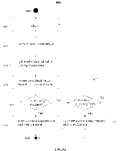
maximum limit placed on the number of cleaning cycles performed). In some
embodiments, the
maximum cleaning limit may be set by the user. In some embodiments, the
maximum cleaning limit
may be based on the first sample, the second sample, or the type of processing
that is occurring. For
example, different samples or different sample processing/analyses may have
different maximum
cleaning limits. If the maximum cleaning limit is not reached, return to step
S51 and continue the
cleaning process until the cleaning requirement is met or the maximum cleaning
limit is reached. If
the maximum cleaning limit is reached, proceed to step S58.
[0126] At step S58, the cleaning process is stopped. Optionally, at step S58,
a message or warning
may be issued to the user, so that the user may take appropriate measures,
such as troubleshooting.
[0127] FIG. 13 is a schematic flowchart of a method 600 for cleaning a sample
processing
instrument according to another embodiment of the present application. Steps
S61, S62, S64 to S68
of method 600 are the same as steps S51, S52, S54 to S58 of method 500, and
therefore are not
described in detail. The method 600 differs from the method 500 in step S63.
The total
measurement value during the monitoring period is acquired at step S53 of the
method 500,
whereas the measurement value is acquired at a predetermined interval at step
S63 of the method
600. The predetermined interval here includes a continuous predetermined
interval and a
superimposed predetermined interval A continuous predetermined interval means,
assuming that
the predetermined interval is 5 seconds, to obtain a measured value from 0 to
the 5th second, a
measured value from the 5th to the 10th second, a measured value from the 10th
to 15th second,
and so on, for example. A superimposed predetermined interval means, assuming
that the
predetermined interval is 5 seconds, to obtain a measured value from 0 to the
5th second, a
18
CA 03234205 2024- 4- 8
WO 2023/065796
PCT/CN2022/113006
measured value from 1st second to the 6th second, and a measured value from
2nd second to the 7th
second, and so on, for example. Accordingly, the calculated value within the
predetermined interval
is obtained at step S64.
[0128] In the method 600, once it is found that the cleaning requirement has
been met, the
monitoring process may be stopped immediately. Therefore, compared with the
method 500, the
method 600 enables the user to learn the information that the cleaning
requirement has been met
more quickly.
[0129] It should be understood that the method according to the present
application is not limited to
the above-mentioned methods 500 and 600, but may be changed according to
requirements. For
example, the method of obtaining the measured value may be changed, and the
set parameters may
be changed. For example, in step S55 or S65, both the measured value and the
calculated value can
be used to determine whether the cleaning requirement has been met. Moreover,
steps of the
method may not necessarily be executed in the described order, but can be
interchanged in order or
executed at the same time without contradiction. In addition, the method may
omit a certain step or
add additional steps.
[0130] In order to facilitate user operations and obtain information, the
method of' the present
application may be carried out with a user interface. The user interface
according to the present
application will be described below with reference to FIGs. 14 to 20.
[0131] Referring to FIG. 14, the user interface 800 may include a menu 810, a
parameter setting
element 820, a monitoring element 840, a setting-applicable-sample element
830, a historical data
viewing element 850 and a control element 860. The menu 810 may include one or
more next-
activity element that enable the user to interact with the sample processing
instrument by
configuring the processing of samples and the cleaning of the sample
processing instrument or
monitoring such processing or cleaning. The next-activity element will be
described in detail below
with reference to FIG. 15 The parameter setting element 820, the monitoring
element 840, the
setting-applicable-sample element 830 and the historical data viewing element
850 may be
displayed on the user interface in response to the selection or operation of
the corresponding next-
activity element of the menu 810, so that the user can input information or
information is displayed
to the user. The parameter setting element 820 is used to receive user input
related to cleaning,
monitoring and carryover (which will be described in detail below with
reference to FIG 16). The
monitoring element 840 is configured to display information related to
cleaning or monitoring
status, monitoring data, monitoring results, monitoring standards, etc., to
the user (which will be
described in detail below with reference to FIGs. 18A to 18E). The setting-
applicable-sample
element 830 includes samples to be monitored, and the user may select samples
to which the
19
CA 03234205 2024- 4- 8
WO 2023/065796
PCT/CN2022/113006
settings at the parameter setting element 820 are applied, so that the sample
processing instrument
may automatically and continuously process multiple samples (which will be
described in detail
below with reference to FIG. 17). The historical data viewing element 850 may
retrieve or view
historical monitoring data according to user request (which will be described
in detail below with
reference to FIG. 19). The control element 860 allows the user to control
various elements
displayed on the user interface or display contents of various elements.
[0132] As shown in FIG. 14, the menu 810, the parameter setting element 820,
the setting-
applicable-sample element 830, the monitoring element 840, the historical data
viewing element
850 and the control element 860 may be displayed simultaneously on one screen,
for example,
within the corresponding boxes. It should be understood that the user
interface according to the
present application should not be limited to the specific example shown in FIG
14, but may be
changed as required. In some embodiments, any subset of these interface
elements may be
displayed simultaneously on the user interface. For example, in some cases,
only the menu 810 and
the parameter setting element 820 may be displayed simultaneously on the user
interface 800. In
some embodiments, the interface elements displayed on the user interface may
be selected based on
a user input. For example, the user may select the setting-applicable-sample
element 830, and in
response, the user interface may show an enlarged setting-applicable-sample
element 830 and none
(or only a subset) of the other interface elements. For example, the
historical data viewing element
850 is optional. Furthermore, the layout of various elements on the user
interface may be changed.
The content and display form of each element may also be changed as required.
[0133] Hereinafter, the elements of the user interface will be described with
reference to specific
examples shown in the figures. These examples are for illustrative purposes
only, and are not a
limitation to the present application.
[0134] FIG. 15 shows an example of the menu 810. As shown in FIG. 15, the menu
810 may
display a number of different next-activity elements, including ''parameter
settings", "setting
applicable samples", "operate cleaning/monitoring", and "view monitoring
report".
[0135] The menu 810 allows the user to select among the different next-
activity elements. For
example, the user may select the next-activity element of the "parameter
setting" of the menu 810.
In response, the parameter setting element 820 may be displayed on the user
interface for the user to
input. In some examples, the parameter setting element may be shown in the
form of an
independent window (for example, a pop-up window), which may also be referred
to as an
operation window or a setting window herein. The parameter setting element may
include the
settings of cleaning parameters, the settings of monitoring parameters, and
the settings of the target
carryover amount.
CA 03234205 2024- 4- 8
WO 2023/065796
PCT/CN2022/113006
[0136] FIG. 16 shows an example of a parameter setting element 820. As shown
in FIG. 16, the
setting of the cleaning parameters includes the cleaning time of a cleaning
cycle and the maximum
number of cleaning cycles. The setting of monitoring parameters includes the
delivery time of the
monitoring solution. In some examples, the target carryover amount may be a
target count (or
approximate count) of carryover particles, a target carryover rate (a
quantification of carryover
particles acceptable/desired to be within the flow cell over a time period
(e.g., per second) as a
monitoring solution is to be flowed through the flow channel), a target
carryover concentration
(expressing a desired concentration of the carryover particles in the volume
of a monitoring solution
that is to be within the flow cell), etc. In addition, in the example of FIG.
16, the setting of the
population to which the sample to be monitored belongs is also included. It
should be understood
that the parameter settings may be changed according to requirements, and are
not limited to the
specific examples shown in the figure. For example, in the parameter setting
element, options for
operating the program (for example, "no cleaning", "cleaning only", "cleaning
and monitoring" as
shown in FIG. 20) may also be set for the user to choose. In the example shown
in FIG. 16, the user
inputs and selects in the form of a text field or a drop-down list. However,
the settings may also be
input in any other suitable way, for example, a dialog box, a radio button, a
slider element, etc.
[0137] After the user clicks the next-activity element of ''setting applicable
sample" of the menu
810, a setting-applicable-sample element 830 is displayed on the user
interface. FIG. 17 shows an
example of a setting-applicable-sample element 830. As shown in FIG. 17, all
the samples to be
monitored are shown in the setting-applicable-sample element 830. Samples may
be distinguished
by the name of the container that contains the sample. There are radio buttons
in front of' each
sample for users to choose. The setting-applicable-sample element 830 allows
users to have
different acceptable cleaning standards following the processing of different
samples (e.g., samples
that are to be run successively) by, for example, letting the user set
different target carryover
amounts for the different samples (e.g., via the example element 820 shown in
FIG. 16, as described
in further detail above). For example, a user may have three samples to run
successively (e.g.,
Sample 1, followed by Sample 2, followed by Sample 3) through the sample
processing instrument.
In this example, as illustrated in FIG. 17, a user may select Sample 1 and
Sample 2 by checking
their respective boxes in the element 830 and set cleaning standards by
setting desired target
carryover amounts (e.g., via the element 820, setting a target carryover rate
and a target
concentration) for both Sample 1 and Sample 2. The user may then select Sample
3, by checking its
respective box (while the boxes for Sample 1 and Sample 2 are unchecked) and
set cleaning
standard for Sample 3 in a similar manner. As another example, the user may
set cleaning standards
for one sample (e.g., Sample 1) and then copy those cleaning standards to one
or more different
21
CA 03234205 2024- 4- 8
WO 2023/065796
PCT/CN2022/113006
samples (e.g., Sample 2) for a similar effect. In some examples, the sample
processing instrument
may automatically process each of the different samples successively and
automatically based on
the pre-set cleaning standards selected for each of the different samples. For
example, Samples 1 to
3 may be processed automatically and successively, with desired cleaning
cycles performed
according to their pre-set cleaning standards, thereby improving the
efficiency of the sample
processing instrument. That is, the user may not need to manually monitor and
submit manual
inputs during the processing of these different samples. It should be
understood that the display of
the sample is not limited to the specific example shown in FIG. 17, but may be
shown in any other
suitable manner or for the user to select or input.
[0138] After the user clicks the next-activity element of "run
Cleaning/Monitoring" in the menu
810, the cleaning/monitoring process is started according to the settings or
selections in FIG. 16 and
FIG. 17. The monitoring element 840 is displayed on the user interface. The
monitoring element
840 may display the cleaning/monitoring state, the measured carryover amount,
the target carryover
amount, and the like to the user.
[0139] The monitoring element 840 may be shown in one or more windows or
modules according
to various stages of cleaning/monitoring. The content related to the entire
monitoring period may
always be displayed on the user interface, and the content related to each
stage of
cleaning/monitoring may be displayed in separate windows (for example, pop-up
windows). It
should be understood that the display content and display form of the
monitoring element 840 are
not limited to the specific examples described herein or shown in the figures,
but may be changed.
For example, the state of the cleaning/monitoring process may be displayed in
a separate state
window, or the final result of the monitoring may be displayed in a separate
browse window.
[0140] FIGs. 18A to 18E show various examples of monitoring elements 840. The
examples of
FIGs. 18A to 18E are different in the content displayed and the form of the
carryover display
according to the various stages of the method.
[0141] FIG. 18A shows a monitoring element 841. In the monitoring element 841,
the state of the
cleaning process includes the cleaning progress and the number of cleaning
cycles. The carryover
measurement data during the monitoring process represents the carryover data
measured during the
entire monitoring process, which is shown in the form of a histogram G1 in
FIG. 18A, where the
abscissa represents the intensity of signal of carryovers (e.g., signal of
light), and the ordinate
represents the count of carryovers (particles). The histogram G1 shows the
measurement data of the
entire monitoring process, so it can always be displayed on the user
interface, such as the upper left
of FIG. 18A. In this histogram Gl, the longer the monitoring time, the larger
the count of
carryovers (particles). It should be understood that, as required, the
measurement data may be
22
CA 03234205 2024- 4- 8
WO 2023/065796
PCT/CN2022/113006
displayed in any other suitable graphs, for example, scatter dot plots,
density plots, pseudocolor
plots, grayscale plots, and/or contour plots. It should be understood that the
measurement data of
the carryover may also be shown in any other suitable form besides the graph.
In some cases, the
measured carryover data may be used to determine whether a desired cleaning
level has been
achieved (e.g., from a determination that the measured carryover is below a
desired threshold). Ti
some examples, the measured carryover amount may be expressed in terms of, for
example, a count
or estimated count of carryover particles present in the flow cell, a
carryover rate (a quantification
of the carryover particles as detected within the flow cell over a time period
(e.g., per second) as the
monitoring solution is flowed through the flow channel), and/or concentration
of carryover
(expressing the concentration of the carryover particles in the volume of the
monitoring solution
that is within the flow cell). In some examples, the measured carryover amount
may be a derived
value that is only based on the carryover data measured by the system (e.g., a
value derived by
applying one or more formulae or functions to the measured carryover data).
The measured
carryover amount is shown in text form in FIG. 18A, as carryover rate
(detection of carryover
particles per second as the monitoring solution is flowed through the flow
channel) and
concentration of carryover. In FIG. 18A, the cleaning/monitoring state, the
measured carryover
amount, and the target carryover amount are displayed in separate pop-up
windows.
[0142] FIG. 18B shows a monitoring element 842. The difference between the
monitoring element
842 of FIG. 18B and the monitoring element of FIG. 18A is that the measured
carryover amount
and the set target carryover amount are also shown in the form of the portion
of FIG. 18B labeled as
G2. Through the portion G2, it can be intuitively seen whether the cleaning
level meets the
requirements. In FIG. 18B, the measured carryover amount is above the target
carryover amount, so
the cleaning standard has not yet been reached.
[0143] FIG. 18C shows a monitoring element 843. The monitoring element 843 of
FIG. 18C is
different from the monitoring element 842 of FIG. 18B in that it also shows
the monitoring result,
for example, the monitoring result after a cleaning cycle. Specifically, in
FIG. 18C, the user is
provided with information indicating that the monitoring result is not met,
and a new cleaning cycle
may start after 3 seconds.
[0144] FIG. 18D shows a monitoring element 844. The difference between the
monitoring element
844 of FIG. 18D and the monitoring element 843 of FIG. 18C is that the
monitoring result indicates
that the cleaning standard has been met.
101451 FIG. 18E shows a monitoring element 845. The difference between the
monitoring element
845 of FIG. 18E and the monitoring element 844 of FIG. 18D is that the
measured carryover
amount and the set target carryover amount are shown in the form of a table.
The measured
23
CA 03234205 2024- 4- 8
WO 2023/065796
PCT/CN2022/113006
carryover amount and the set target carryover amount are displayed in the same
table, allowing the
user to intuitively determine whether the cleaning standard has been met.
[0146] It should be understood that the measured actual carryover amount and
target carryover
amount are not limited to being displayed in texts (as shown in FIG. 18A),
graphs (as shown in FIG.
18B to FIG.18D) and tables (as shown in FIG. 18E), but can be shown in any
other suitable form.
[0147] After the user clicks the next-activity element of "View Monitoring
Report" in the menu 810,
a report may be displayed on an interface such as the historical data viewing
element 850. The
historical data viewing element 850 includes historical data that has been
monitored. FIG. 19 shows
an example of the historical data viewing element 850. Through the historical
data viewing element
850, it is convenient for users to query historical monitoring data at any
time. The display content of
the historical data viewing element 850 may be determined according to user
requirements.
[0148] The user interface described with reference to FIGs. 14 to 19 may be
integrated into the user
interface of sample processing, as shown in FIG. 20. In the example shown in
FIG. 20, the option of
"operation cleaning and monitoring after processing" may also be provided in
the settings window.
This option is for the user to choose before processing the sample. Once the
user selects this option
in the setting window, cleaning and monitoring are automatically performed
after processing the
sample, without waiting for the user's instructions or settings. In addition,
in the example shown in
FIG. 20, other program options may also be provided in the setting window, for
example, "no
cleaning", "cleaning only", "cleaning and monitoring". Although not shown in
FIG. 20, then, it
should be understood that the program options may also include an option
specifying that only
monitoring should be performed (e.g., an option specifying "monitoring only").
[0149] Control elements may be displayed in the user interface or various
elements, for example,
including but not limited to "Switch on", "Start", "Stop", "Interrupt",
"Repeat", "Close", "Apply",
"Cancel", etc., depending on user requirements. The control element may be in
the form of one or
more control buttons, for example, as shown at the bottom of the windows in
FIGs. 16 to 19.
[0150] The above system or method may be implemented by the control unit 40.
The control unit
40 in the present application may include a processor implemented as a
computer or a computing
system. The method of operating and cleaning the sample processing instrument
and the method of
monitoring the cleaning of the sample processing instrument described herein
may be implemented
by one or more computer programs executed by the processor of the computer.
The computer
programs include processor-executable instructions stored on a non-transitory
tangible computer-
readable medium. The computer programs may also include the stored data Non-
limiting examples
of the non-transitory tangible computer-readable medium are non-volatile
memory, magnetic
storage devices, and optical storage devices.
24
CA 03234205 2024- 4- 8
WO 2023/065796
PCT/CN2022/113006
101511 The term computer-readable medium does not include transient electrical
or electromagnetic
signals that propagate by means of the medium (such as on a carrier); the term
computer-readable
medium may therefore be considered to be tangible and non-transitory. Non-
limiting examples of
non-transitory tangible computer-readable medium are non-volatile memory (such
as flash memory,
erasable programmable read-only memory or mask read-only memory), volatile
memory (such as
static random access memory circuit or dynamic random access memory), magnetic
storage
medium (such as analog or digital magnetic tapes or hard drives), and optical
storage medium (such
as CD, DVD, or Blu-ray Disc).
101521 Although the present application has been described with reference to
exemplary
embodiments, it should be understood that the present application is not
limited to the specific
embodiments described and illustrated herein. Without departing from the scope
defined by the
claims, those skilled in the art can make various changes to the exemplary
embodiments. Provided
that there is no contradiction, the features in the various embodiments can be
combined with each
other. Alternatively, a certain feature in the embodiment may also be omitted.
25
CA 03234205 2024- 4- 8