Note: Descriptions are shown in the official language in which they were submitted.
CA 03234309 2024-03-28
WO 2023/056251 PCT/US2022/077082
EXEMPLAR ROBOT LOCALIZATION
CROSS-REFERENCE TO RELATED APPLICATION
[0001] This application claims the benefit of U.S. Provisional Application No.
63/249,686, filed September 29, 2021, titled "Exemplar Robot Localization",
and U.S.
Non-Provisional Application No. 171952,937, filed September 26, 2022 titled
"Exemplar
Robot Localization".
BACKGROUND
[0002] A monitoring system for a property can include various components
including
sensors, cameras, and other devices. For example, the monitoring system may
use the
camera to capture images of people or objects of the property.
SUMMARY
[0003] This specification describes techniques, methods, systems, and other
mechanisms for exemplar generation and localization. Localizing a robot may be
useful For example, a property may include a number of robots that complete
tasks
involving navigating around the property. To successfully carry out missions
while
avoiding various obstacles that may exist on the property, the robot may use
localization
processes to determine its location at the property.
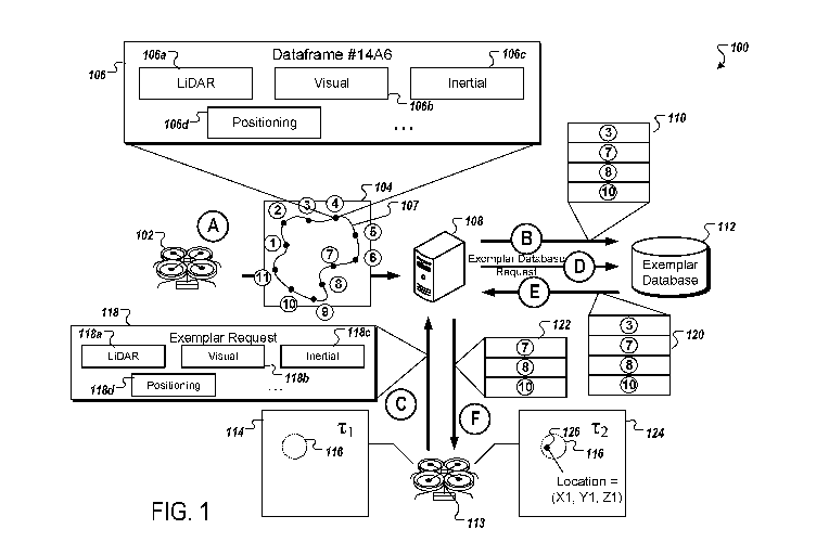
[0004] In order to perform localization processes, a robot may obtain data
from one or
more onboard sensors. The sensors may be used to determine an approximate
location. In some cases, the robot may supplement sensor data with previously
obtained data, such as exemplars, to determine its location with greater
accuracy. The
exemplars may represent data captured from one or more known locations at a
property. The exemplars may include a number of features across one or more
types of
obtained data (e.g,, monocular camera imagery, visual-inertial odometry (V10),
time of
flight (TOF), Light Detection and Ranging (LiDAR), sound navigation and
ranging
(SONAR), and light sensor data among others). Exemplars may be provided to a
robot
1
CA 03234309 2024-03-28
WO 2023/056251 PCT/US2022/077082
upon request and the robot may compare features across one or more types of
data
obtained by the requesting robot and features of the obtained exemplar data,
[0005] In some implementations, exemplars are generated by a control unit of a
system. For example, the control unit may obtain one or more data streams from
sensors operating at a property, In some cases, the sensors may be fixed to a
robot.
The control unit can determine sampling rates for the data streams based on
features
detected within the data streams. The sampling rates may be used to determine
what
data frames are selected as exemplars. For example, a sampling rate may be
increased if LiDAR sensors detect that a route traverses a doorway connecting
rooms.
A sampling rate may similarly be increased if a number of detected objects in
a visual
field satisfies a threshold. A sampling rate may be decreased if sensors
become
saturated, data is corrupted, or a number of detected features is below a
threshold. In
this way, exemplars may be selected to reduce storage requirements while
maximizing
data effective for the localization of robots.
[0006] In some implementations, a robot generates and sends exemplar requests
to a
control unit. The control unit may provide exemplars from among an exemplar
set. The
control unit may select the exemplars that may be useful for a current mission
or at a
particular location. The robot may receive the exemplars and may use them for
one or
more localization processes. In this way, the robot may be constructed at
reduced cost
with less onboard memory devoted to exemplar data compared to a robot that
stores all
previously obtained sensor data at a property or a robot that stores all
obtained sensor
data from all exemplars. In addition, efficiency may improve by processing
only the
reduced set of applicable exemplars.
[0007] One innovative aspect of the subject matter described in this
specification is
embodied in a method that includes obtaining sensor data from a robot
traversing a
route at a property, determining sampling rates along the route using the
sensor data
obtained from the robot; selecting images from the sensor data as exemplars
for robot
localization using the sampling rates along the route; determining that a
second robot is
in a localization phase at the property; and providing representations of the
exemplars
for robot localization to the second robot.
2
CA 03234309 2024-03-28
WO 2023/056251 PCT/US2022/077082
[0008] Other implementations of this and other aspects include corresponding
systems, apparatus, and computer programs, configured to perform the actions
of the
methods, encoded on computer storage devices. A system of one or more
computers
can be so configured by virtue of software, firmware, hardware, or a
combination of
them installed on the system that in operation cause the system to perform the
actions.
One or more computer programs can be so configured by virtue of having
instructions
that, when executed by data processing apparatus, cause the apparatus to
perform the
actions.
[0009] The foregoing and other embodiments can each optionally include one or
more
of the following features, alone or in combination. For instance, in some
implementations, determining the sampling rates includes detecting one or more
features in the sensor data.
[0010] In some implementations, actions include adjusting a current sampling
rate
using the detected one or more features in the sensor data. In some
implementations,
the one or more features include one or more of the following: detection of
objects,
detection of object characteristics, detection of objects or characteristics
in LiDAR data,
visual data, inertial data, velocity of the robot, or positioning data.
[0011] In some implementations, selecting the images from the sensor data
using the
sampling rates along the route includes determining a sampling rate for a
portion of the
route; and selecting images obtained along the portion of the route at the
sampling rate,
[0012] In some implementations, each of the sampling rates indicate a number
of the
exemplars to be selected per a number of data frames captured in the sensor
data. In
some implementations, actions include obtaining a request from the second
robot; and
determining that the second robot is in a localization phase at the property
using the
request from the second robot,
[0013] In some implementations, actions include selecting non-visual data from
the
sensor data as the exemplars for robot localization. In some implementations,
the non-
visual data includes one or more of LiDAR data, light sensor data, inertial
data,
positioning data, or SONAR data,
3
CA 03234309 2024-03-28
WO 2023/056251 PCT/US2022/077082
[0014] In some implementations, actions include providing non-visual data from
the
sensor data to the second robot. in some implementations, actions include
determining
a second route of the second robot; comparing a first set of one or more
values
representing locations of one or more exemplars of the exemplars with a second
set of
one or more values representing one or more locations along the second route;
selecting a set of one or more exemplars as applicable exemplars; and
generating the
representations of the exemplars, where the representations include a
representation of
each applicable exemplar of the applicable exemplars.
[0015] In some implementations, the first set of one or more values
representing the
locations of the set of one or more exemplars of the exemplars and the second
set of
one or more values representing the one or more locations along the second
route are
coordinate values representing space in a coordinate system.
[0016] In some implementations, actions include obtaining an approximate
location of
the second robot; determining a set of one or more exemplars from the
exemplars that
satisfy a matching threshold with the approximate location; and generating the
representations of the exemplars, where the representations include a
representation of
each exemplar of the set of one or more exemplars.
[0017] In some implementations, actions include obtaining data from a
monitoring
system at the property indicating the second robot is either traversing, or
will traverse, a
specific route; determining a set of one or more exemplars from the exemplars
that
satisfy a matching threshold with locations along the specific route; and
generating the
representations of the exemplars, wherein the representations include a
representation
of each exemplar of the set of one or more exemplars,
[0018] Another innovative aspect of the subject matter described in this
specification
is embodied in a non-transitory computer-readable medium storing one or more
instructions executable by a computer system to perform operations that
include
obtaining sensor data from a robot traversing a route at a property;
determining
sampling rates along the route using the sensor data obtained from the robot;
and
selecting images from the sensor data as exemplars for use providing
representations
of the exemplars for robot localization at the property by a second robot.
4
CA 03234309 2024-03-28
WO 2023/056251 PCT/US2022/077082
[0019] Another innovative aspect of the subject matter described in this
specification
is embodied in a system, that includes one or more computers and machine-
readable
media interoperably coupled with the one or more computers and storing one or
more
instructions that, when executed by the one or more computers, perform
operations that
include determining that a robot is in a localization phase at a property; and
providing, to
the robot, representations of exemplars, selected as images from sensor data
obtained
from a second robot using sampling rates, for robot localization,
[0020] The details of one or more implementations are set forth in the
accompanying
drawings and the description, below. Other potential features and advantages
of the
disclosure will be apparent from the description and drawings, and from the
claims.
BRIEF DESCRIPTION OF THE DRAWINGS
[0021] FIG. 1 is a diagram showing an example of a system for exemplar
generation
and localization.
[0022] FIG. 2 is a diagram showing an example of a control unit generating
exemplars.
[0023] FIG. 3 is a flow diagram illustrating an example of a process for
exemplar
generation and localization.
[0024] FIG. 4 is a flow diagram illustrating an example of a process for robot
localization using exemplars.
[0025] FIG. 5 is a diagram illustrating an example of a property monitoring
system.
[0026] Like reference numbers and designations in the various drawings
indicate like
elements.
DETAILED DESCRIPTION
[0027] FIG. 1 is a diagram showing an example of a system 100 for exemplar
generation and localization. The system 100 includes a drone 102, a control
unit 108,
an exemplar database 112, and a drone 113. The drone 102 sends obtained data
104
to the control unit 108. After processing the data 104, the control unit 108
sends a
CA 03234309 2024-03-28
WO 2023/056251 PCT/US2022/077082
selected portion of the data 104 as exemplars 110 to the exemplar database
112. The
drone 113 sends an exemplar request 118 to the control unit 108. The control
unit 108,
after processing the exemplar request 118, obtains exemplars 120 from the
exemplar
database 112. The control unit 108 processes the exemplars 120 to select
exemplars
122 to provide to the drone 113. The control unit 108 provides the exemplars
122 to the
drone 113.
[0028] Although the drone 102 and the drone 113 are depicted in FIG. 1 as
aerial
drones, the drone 102 and the drone 113 may be any type of device with
equipped
sensors or with navigation capabilities. In some implementations, one or more
sensors
may perform actions attributed to the drone 102. For example, instead of
obtaining the
data 104 from the drone 102, the control unit 108 may obtain data from sensors
that are
not affixed to a robot but are positioned at a property.
[0029] In some implementations, the drone 102 and the drone 113 are the same
drone. For example, a given drone, depicted as the drone 102, can obtain data
104.
The same drone, depicted as the drone 113, can send the exemplar request 118
and
obtain the exemplars 120. In general, the same drone that obtains data for the
control
unit 108 to generate the exemplars 110 can be the drone that requests and
obtains the
exemplars 120 selected by the control unit 108,
[0030] In some implementations, the control unit 108 includes a processor or
other
control circuitry configured to execute instructions of a program. A program
executed
by the control unit 108 may include operations for obtaining and processing
the data
104 from the drone 102, sending and obtaining exemplars to and from the
exemplar
database 112, and obtaining and processing the exemplar request 118. In some
cases,
the exemplar database 112 may include memory onboard the control unit 108. In
some
cases, the exemplar database 112 may include memory communicably connected to
the control unit 108, e.g., through a wired or wireless network.
[0031] In one example, the system 100 of FIG. 1 proceeds from stage A to stage
F. In
stage A, the drone 102 sends the data 104 to the control unit 108. The data
104 may
include one or more data frames. Each data frame includes data of one or more
data
types. For example, data frame 106 includes LiDAR data 106a, visual data 106b,
6
CA 03234309 2024-03-28
WO 2023/056251 PCT/US2022/077082
inertial data 106c, positioning data 106d, among others. Data frame 106 is
associated
with a unique identification "14A6." In general, any form of identification
may be used to
uniquely identify a data frame.
[0032] In some implementations, data frames include data types of varying
degrees of
quality. In some cases, data may be missing entirely. For example, a data
frame may
include visual data with dearly defined objects and LiDAR data that is beyond
a
maximum threshold range and therefore likely inaccurate. Based on the visual
and
LiDAR data of the data frame, components of the system 100 can determine one
or
more quality scores of the data frame. Each of the one or more quality scores
of the
data frame may indicate a relative quality of data stored within the data
frame. A quality
score may be determined based on comparing data from one or more other data
frames
or based on a quality score specified by a user.
[0033] In some implementations, data with more features are indicated as
higher
quality than data with fewer features. In the case of visual data, components
of the
system 100, such as the control unit 108, may determine that data with a lame
number
of detected objects is of higher quality than data with few detected objects.
In the case
of LiDAR data, the control unit 108 may determine that data with distinct
LiDAR
characteristics or changes is of higher quality than data with little change
or LiDAR
measurements that indicate the measurements may be less accurate (such as
LiDAR
data indicating a far distance, e.g., greater than 10 meters),
[0034] In some implementations, a user provides one or more examples of
different
degrees of quality for one or more data types. For example, the user can
provide visual
data associated with a user quality indicator. The user may mark an image with
blurry
features as lower quality than an image with clearly defined features, Using
one or
more examples provided by a user, the system 100 may determine a quality
indicator
for one or more data types of data frames based on comparing new data with
examples
and corresponding quality indicators provided by the user. In some cases, the
quality
indicator may include a score indicating the quality of data relative to a
range including
the score.
CA 03234309 2024-03-28
WO 2023/056251 PCT/US2022/077082
[0035] In some implementations, movement or location of a drone may impact
data
quality. For example, at a first location, the drone 102 may obtain visual
data of high
quality as indicated by a quality score. Various location or movement
variables, such as
adequate lighting or lack of rapid movement, may contribute to higher quality
visual
data. Components of the system 100, such as the drone 102 or the control unit
108
may determine carious location or movement variables based on data from
inertial
sensors, location sensors, and light sensors, among others. At the first
location, the
drone 102 may also obtain data of another type which may be of a lower quality
than
the visual data obtained. For example, the drone 102 may obtain LiDAR data at
the first
location. The first location may be the center of a large room. LiDAR sensors
of the
drone 102 may have a maximum distance threshold beyond which measurements may
be less accurate. In this case, components of the system 100, such as the
control unit
108 or the drone 102, may mark LiDAR measurements indicating measurements
satisfying a threshold as lower quality based on known limitations of the
current LiDAR
sensor used. In general, sensor limitations may be combined with location and
movement data in order to determine a likely quality indication of the
obtained data of
the corresponding data type. In this way, the system 100 may be more likely to
determine exemplars with high quality data.
[0036] In some implementations, movement of sensors may decrease quality of
some
data types more than others. For example, rapid movement of visual data
sensors may
degrade the visual data obtained during the rapid movement, However, other
sensors
may be able to obtain high quality data in the same circumstance. For example,
LiDAR
sensors may, depending on other factors of the location such as distance to
objects,
obtain high quality LiDAR data in spite of rapid movement by the LiDAR
sensors. In the
case of FIG. 1, if the drone 102 includes both visual data sensors and LiDAR
sensors
and moves rapidly, the drone 102, or subsequent processing system, such as the
control unit 108, can determine the visual data obtained during the rapid
movement is of
lower quality than the LiDAR data obtained during the rapid movement based on
the
rapidity of the movement and specifications of the visual and LiDAR sensors.
Components of the system 100, such as the drone 102 or the control unit 108,
can
scale a quality of obtained data based on predetermined expressions relating a
quality
8
CA 03234309 2024-03-28
WO 2023/056251 PCT/US2022/077082
indication with a (i) particular type or extent of movement or type or extent
of
environmental condition (e.g., inclement weather, lighting conditions, among
others) and
(ii) known specifications of sensors used to obtain the data
[0037] In some implementations, components of the system 100 discard frames
based on quality. For example, the control unit 108 may determine a quality
indication
for a first data frame. The quality indication for the first data frame may
indicate an
average, minimum, maximum, or other result of an expression of one or more
quality
scores of data types included within the data frame. The control unit 108 may
compare
the quality indication with a threshold and discard the first data frame based
on the
quality indication satisfying the threshold.
[0038] In some implementations, components of the system 100 discard data
within
frames based on quality. For example, the control unit 108 may determine a
quality
indication for data within a first data frame. The control unit 108 may obtain
one or
more quality examples submitted by a user and compare the one or more quality
examples to the data within the first data frame to determine the quality
indication. The
control unit 108 may compare the data with one or more other data of the same
data
type from other frames to determine the quality indication. The control unit
108 may
obtain movement, location, or environmental sensor data and determine, based
on the
movement, location, or environmental sensor data, known characteristics of a
sensor
that obtained the data within the first data frame, and one or more
expressions relating
a quality score with (i) movement, location, or environmental sensor data and
(ii) known
characteristics of a sensor that obtained the data within the first data
frame. The control
unit 108 can use the obtained sensor data, sensor characteristics, and known
expressions to determine the quality indication. The control unit 108 may
compare the
quality indication with a threshold and discard the data of the first data
frame based on
the quality indication satisfying the threshold.
[0039] In some implementations, memory resources are conserved from discarding
data. For example, a database, such as the exemplar database 112 includes data
frames determined as exemplars. The exemplars may include only data that
satisfies a
threshold. Data within an exemplar frame that does not satisfy a threshold,
may be
9
CA 03234309 2024-03-28
WO 2023/056251 PCT/US2022/077082
discarded. In this way, the system 100 may conserve memory. The system 100 may
also increase efficiency by discarding, and therefore not processing poor
quality data
during exemplar determination and retrieval,
[0040] In some implementations, data frames of data 104 are obtained by the
drone
102 as the drone traverses a route of a property. Route 107 is shown
graphically in
FIG. 1 as a simplified two-dimensional representation of a route traversed at
a property
by the drone 102. A coordinate system may be used to indicate a determined
location
for each data frame of the data 104. Although 11 data frames are shown in the
data
104, more data frames may be obtained. For example, data frames along the
route 107
between the numbered data frames may be obtained in a given implementation.
Each
data frame along the route 107, may include data of different types as shown
in data
frame 106 and discussed further in reference to FIG. 2
[0041] The control unit 108 obtains the data 104 from the drone 102. The
control unit
108 processes the data 104 and the included data frames, e.g., data 106a-d of
data
frame 106, to detect features of the data 104. The control unit 108 selects
frames of the
data 104 based on the detected features. The control unit 108 may use a
sampling rate
which may increase or decrease depending on the features detected in the data
104.
The processing and exemplar generation is shown further in FIG. 2 and
corresponding
written description.
[0042] In stage B, the control unit 108 generates exemplars 110 based on the
obtained data 104 and processing of the obtained data 104. The exemplars 110
are
sent to the exemplar database 112. The exemplar database 112 obtains the
exemplars
110 and stores the exemplars 110. In some implementations, the exemplar
database
112 may use indexes to organize various exemplars associated with a number of
different obtained datasets. Indexes may include geographic information or
feature
information to aid in retrieval processes, For example, an index may include
an
indication that the corresponding stored data was captured in a living room of
the
property or other geographic location. If exemplars for the particular
geographic
location is needed, the control unit 108, or other processor, may identify,
based on the
index of the exemplar database 112, data corresponding to a living or other
geographic
CA 03234309 2024-03-28
WO 2023/056251 PCT/US2022/077082
location. The control unit 108 may send the exemplars 110 with corresponding
descriptions or identifiers to aid in later retrieval.
[0043] In stage C, the drone 113 is in a localization phase. The drone 113 may
determine an approximate location 116 as shown in map 114. The approximate
location 116 may be determined at a first time (Ti). The approximate location
116 may
indicate a determined location with a determined degree of uncertainty which
may be
graphically shown as two-dimensional area. The drone 113 generates an exemplar
request 118 and sends the request 118 to the control unit 108. The exemplar
request
118 may include data types similar to the data types of the data 104
previously
obtained. In the example of FIG. 1, the exemplar request 118 includes data of
the same
types as data in the data 104. For example, the exemplar request 118 includes
LiDAR
data 108a, visual data 108b, inertial data 108c, and positioning data 108d and
the data
frame 106 of the data 104 similarly includes LiDAR data 106a, visual data
106b, inertial
data 106c, and positioning data 106d.
[0044] In some implementations, the drone 113 initiates localization after
determining
drift in a location tracking process has occurred. For example, the drone 113
may be
using an inertial-based location tracking system such as VIO to track its
location over
time based on a known starting location and a series of accelerations
corresponding to
movements after the known starting location. The VIO method may help to reduce
processor usage compared to location methods that rely on object detection in
visual
sensor data to determine a location. However, drift in the VIO processing may
occur
where a current location determined by VIO does not match an actual current
location of
the drone 113. In an actual implementation, a drone 113 may expect to sense a
certain
object or feature based on an obtained map or known features of a property and
does
not (e.g., the drone 113 uses visual, LiDAR, SONAR, ToF, light sensors among
others
to determine that what should be a doorway, according to known, pre-obtained
features
of a property, is more likely a wall based on the sensor measurements). The
drone 113
may then initiate localization processes which may include sending an exemplar
request
such as the exemplar request 118.
11
CA 03234309 2024-03-28
WO 2023/056251 PCT/US2022/077082
[0045] In some implementations, the drone 113 compares one or more values
corresponding to sensor differences to a threshold. For example, the drone 113
may
determine that sensor discrepancies between an actual and expected sensor
value is
above an absolute value. The drone 113 may determine that sensor discrepancies
between an actual and expected sensor value is above a percentage of one or
more of
the expected value and the actual value. The drone 113 may determine that
sensor
discrepancies between an actual and expected sensor value is above a threshold
for a
ratio between expected and actual (e.g., a ratio may be used where the larger
of the
expected and actual values is the denominator and the smaller is the numerator
and a
threshold may be a deviation from 1).
[0046] In some implementations, the drone 113 may perform localization
periodically.
For example, the drone 113 may periodically initiate a localization process
(e.g., every
minute) and request exemplars according to the determined period of time. In
some
cases, a rate for localization may increase in service scenarios where
accuracy is
desired. For example, when grabbing an item, interacting with features of a
property, or
performing operations in an emergency situation, such as a fire or break-in
attempt, the
drone 113 may change a localization rate to increase the rate at which it
requests and
receives exemplars and performs localization. The system 100 may include a
system
parameter, such as emergency override, or specific missions of the drone 113
may
change the rate at which the drone 113 performs localization.
[0047] The drone 113 sends the exemplar request 118 to the control unit 108.
The
control unit 108 obtains and processes the exemplar request 118. The control
unit 108
uses the data 118a-d of the request 118 to determine which exemplars stored in
the
exemplar database 112 to provide to the drone 113. In some implementations,
the
control unit 108 selects exemplars corresponding to a location within a
present distance
from the approximate location 116 determined by the drone 113. The control
unit 108
may determine the approximate location 116 from the exemplar request 118
(e.g., the
inertial data 118c and the positioning data 118d) or the approximate location
116 may
be included directly in the exemplar request 118. The control unit 108 may
compare the
approximate location 116 to locations corresponding to exemplars in the
exemplar
database 112. Locations corresponding to exemplars may be stored with
exemplars
12
CA 03234309 2024-03-28
WO 2023/056251 PCT/US2022/077082
and may indicate the location at which the data used to generate the exemplar
was
obtained.
[0048] In some implementations, the approximate location 116 may be determined
using visual inertial odometry (V10). Data of the exemplar request 118, such
as the
inertial data 118c and the positioning data 118d, may indicate the approximate
location
116 determined using V10. A center of the approximate location 116, such as a
determined location which may be combined with a level of location uncertainty
to
determine the approximate location 116, may be compared to the locations
associated
with one or more of the exemplars stored in the exemplar database 112 in order
to
determine applicable exemplars 122 provided to the drone 113 for the
localization of the
drone 113.
[0049] In stage 0 and stage E, the control unit 108 retrieves the exemplars
120 from
the exemplar database 112. In some implementations, the control unit 108 pre-
processes the exemplar request 118 to determine a location or other feature
and then
obtains one or more exemplars that match either the location or the features
(e.g., the
control unit 108 may obtain exemplars in a directory of the exemplar database
112
corresponding to a location if the exemplar request 118 indicates the drone
113 is at the
location). In some implementations, the control unit 108 obtains one or more
exemplars
from the exemplar database 112. The control unit 108 may obtain the one or
more
exemplars from the exemplar database 112 and then process the one or more
exemplars with the exemplar request 118 to determine exemplars 122 to send to
the
drone 113, The control unit 108 can send an exemplar database request to the
exemplar database 112 to retrieve one or more exemplars.
[0050] In some implementations, an exemplar that matched most with a data
obtained
by the drone 113 is included in the exemplars 122. For example, the control
unit 108
can compare the data 118a-d of the exemplar request 118 to the exemplars 120
obtained from the exemplar database 112. Various features included in the
exemplar
request 118 and the exemplars 120 may be used to determine matches. For
example,
features of the LiDAR data from the exemplar request 118 and the exemplars 120
may
be compared to determine what exemplars match most closely, or within a
13
CA 03234309 2024-03-28
WO 2023/056251 PCT/US2022/077082
predetermined threshold. LiDAR features may include the distance from a given
LiDAR
sensor, such as the LiDAR sensor of the drone 102 and the LiDAR sensor of the
drone
113, and objects within three-dimensional space.
[0051] In some implementations, the control unit 108 compares features of the
visual
data 118b to features of the visual data of the exemplars 120. For example,
the control
unit 108 may perform object detection on the visual data 118b of the exemplar
request
as well as the visual data of one or more of the exemplars 120. Each detection
may
have an associated space and location associated with it. The control unit 108
may
compare detections of objects or features within the visual data 118b to
visual data of
the exemplars 120 (e.g., the control unit 108 can determine can compute an
overlap
area between detections of the visual data 118b and detections of the visual
data of the
exemplars 120). The control unit 108 may compare multiple comparisons to
determine
which of the exemplars 120 most match the data of the exemplar request 118.
The
control unit 108 may provide the most applicable or a certain number of most
applicable
exemplars to the drone 113. In the example of FIG. 1 the control unit 108
provides the
most applicable 3 exemplars to the drone 113.
[0062] In stage F, the control unit 108 provides the exemplars 122 to the
drone 113.
As with other data transfers shown in FIG. 1, the exemplars 122 may be sent
using a
wired or wireless network which connect the control unit 108 to the drone 113.
The
drone 113 obtains the exemplars 122. The exemplars 122 are a subset of the
exemplars stored in the exemplar database 112 that are most applicable for
localization
processes of the drone 113,
[0053] The drone 113 uses the exemplars 122 at a second time (T2) after T1 to
perform localization. For example, the drone 113 may determine a distance
between an
actual current location of the drone 113 and a location associated with one or
more of
the exemplars 122. The drone 113 may use differences in the locations of
various
objects or differences in sensor measurements between the data obtained by the
drone
113 and the data of the exemplars 122. For example, the drone 113 may detect a
feature with a size and angle in visual data obtained by the drone 113 and
compare it
with the feature represented in one or more of the exemplars 122. The feature
may be
14
CA 03234309 2024-03-28
WO 2023/056251 PCT/US2022/077082
recognized by certain characteristics, such as color or shape. A difference in
size and
angle between the feature represented in data obtained by the drone 113 and
the
feature represented in the data of the exemplars 122 may indicate a difference
in where
a sensor was when it obtained the corresponding data. The location difference
from
such a comparison may be applied to the known location associated and included
with
the exemplars 122 and may indicate a current location of the drone 113.
[0054] In some implementations, data obtained by the drone 113 used by the
drone
113 to compare with data of the exemplars 122 for localization is obtained
after
receiving the exemplars 122. For example, after receiving the exemplars 122,
the
drone 113 may re-obtain data similar to the data 118a-d included in the
exemplar
request 118. The data obtained by the drone 113 after receiving the exemplars
122
may be more current than the data 118a-d of the exemplar request 118
especially if the
drone 113 has moved since sending the exemplar request 118.
[0055] In some implementations, an elapse time threshold is used to determine
whether to re-obtain data. For example; the drone 113 may start an elapse time
counter at the time it sends the exemplar request 118 to the control unit 108
or at the
time corresponding to when the data 118a-d of the exemplar request 118 was
obtained
by sensors of the drone 113. In some cases, the data 118a-d includes
timestamps
indicating when the data 118a-d was obtained. If the elapse time counter
satisfies a
threshold when the exemplars 122 are received, the drone 113 may determine to
re-
obtain data of the exemplar request 118 so as to more accurately determine its
location.
[0056] The drone 113 uses the exemplars 122 to determine location 126 as shown
on
map 124. The location 126 exists within the predicted area of the approximate
location
116. In some cases, if the location 126 satisfies a difference threshold when
compared
to the area of the approximate location 116, the drone 113 may re-request
exemplars or
may re-determine a location based on the obtained exemplars 122. Checking the
determined location 126 against the approximate location 116 may prevent the
drone
113 from propagating a mistake in localization to subsequent navigation
actions. In
some cases, the determined location 126 is updated as the current location of
the drone
113 and the drone 113 may continue a route or task using the location 126 as a
base
CA 03234309 2024-03-28
WO 2023/056251 PCT/US2022/077082
from which to track differences in order to maintain a current location. As
mentioned,
the drone 113 may use VIO to track location changes from the location 126
after
localization using the exemplars 122.
[0057] In some implementations, the control unit 108 performs adjustments on
the
data 118a-d of the exemplar request 118 based on the data 118a-d. For example,
the
control unit 108 may determine a time when the data 118a-d was obtained and
adjust
the data 118a-d to account for an elapse time between receiving the exemplar
request
118 from the drone 113 and an expected time corresponding to providing
exemplars
122 to the drone 113 or expected time corresponding to the drone 113
performing
localization using the exemplars 122. The control unit 108 may adjust various
features
of the data 118a-d. For example the control unit 108 may use a timestamp
corresponding to the data 118a-d and inertial data 118c or other type of data,
such as a
projected route or path, to determine how the drone 113 will likely move
during the
elapse time. The control unit 108 can then provide exemplars that more closely
match
the data 118a-d adjusted as if the sensors obtaining the data 118a-d where at
a location
indicated by predicting the path of the drone 113. Geometry of shapes and
three-
dimensional indications from the data 118a-d may be used to predict the view
of shapes
as they would be viewed from a predicted future location of the drone 113.
[0058] hi some implementations, exemplars with the greatest number of matching
features are provided to the drone 113. For example, the control unit 108 may
determine a number of visual features in one or more exemplars 120 obtained
from the
exemplar database 112. The visual features determined by the control unit 108
may be
used to uniquely identify one or more objects represented in the data of the
exemplars
120 obtained from the exemplar database. The control unit 108 may determine a
number of visual features in the data 118a-d of the exemplar request. The
visual
features determined from the data 118a-d may also be used to uniquely identify
one or
more objects represented in the data 118a-d as is known in the art. The
control unit
108 may then determine how many objects represented in the exemplars match
objects
represented in the data 118a-d. The control unit 108 may provide the exemplar
with the
most matches or multiple exemplars based on a ranking of most matches
depending on
implementation.
16
CA 03234309 2024-03-28
WO 2023/056251 PCT/US2022/077082
[0059] In some implementations, exemplars with a large number of features may
be
selected over exemplars with few features. For example, as discussed herein,
the
control unit 108 may determine features of the data from the exemplars, In the
case of
visual data, the exemplars with a large number of detected objects may be
selected
over an exemplar with few detected objects. In the case of LiDAR data,
exemplars with
distinct LiDAR characteristics or changes may be selected over an exemplar
with little
change or LiDAR measurements that indicate the measurements may be less
accurate
(such as LiDAR data indicating afar distance, e.g., greater than 10 meters),
[0060] FIG. 2 is a diagram showing an example of the control unit 108
generating
exemplars 110. The control unit 108 is shown as in FIG. 1 with greater detail
as to the
processing of the data 104.
[0061] The control unit 108 obtains the data 104. As shown in FIG. 1, the data
104
may be obtained by a drone, robot, or other device or sensor. The data 104 may
be
sent or retrieved by the control unit 108 over a communications network. The
data 104
includes multiple data frames which include data of one or more different
types. The
data 104 is shown graphically in 210 as processed by the control unit 108. The
data
104 includes data frames 230a-k. The data 104 may include more than the data
frames
230a-k but, for ease of explanation, we will consider only data frames 230a-k.
[0062] The data frames 230a-k include different data types. For example, as
shown in
210, the data frames 230a-k include frames from a LiDAR data stream 220 of the
LiDAR data type, a visual data stream 222 of the visual data type, an inertial
data
stream 224 of the inertial data type, a positioning data stream 226 of the
positioning
data type, among others. In general, any number or types of data may be
obtained as
the data 104 and processed by the control unit 108.
[0063] In some implementations, at least some of the data frames 230a-k can
include
different types of data than the other data frames 230a-k. For instance, a
first data
frame 230a can include LiDAR data, visual data, and positioning data and a
second
data frame 230a can include visual data, inertial data, and positioning data.
[0064] The data frames 230a-k correspond to the locations shown in the
graphical
representation of the data 104. For example, data frame 230a corresponds to
the
17
CA 03234309 2024-03-28
WO 2023/056251 PCT/US2022/077082
beginning of the route 107 and includes data of different types as captured at
a time and
place at a property. For discussion purposes, data frame 230a Will be
considered. Data
frames b-k include traits and features similar to the data frame 230a as
discussed
herein.
[0065] The data frame 230a includes LiDAR data from the LiDAR data stream 220.
The LiDAR data stream 220 may be obtained from one or more LiDAR sensors over
a
period of time. The data frame 230a includes data from the LiDAR data stream
220
over a subset of the period of time. The one or more LiDAR sensors may obtain
measurements in one or more dimensions. The measurements may indicate
distances
from the one or more LiDAR sensors to various objects at a property. The LiDAR
sensors may be affixed to a drone, robot, or electronic device.
[0066] The data frame 230a includes visual data from the visual data stream
222.
The visual data stream 222 may be obtained from one or more visual data
sensors over
a period of time. The data frame 230a includes data from the visual data
stream 222
over a subset of the period of time. The one or more visual data sensors may
include
camera devices. In some cases, the visual data sensors obtain visual data that
depicts
one or more objects of a property using pixels. The pixels may include
parameters
indicating an intensity or color in order to represent objects. The visual
data sensors
may be affixed to a drone, robot, or electronic device.
[0067] The data frame 230a includes inertial data from the inertial data
stream 224.
The inertial data stream 224 may be obtained from one or more inertial data
sensors
over a period of time. The data frame 230a includes data from the inertial
data stream
224 over a subset of the period of time. The one or more inertial data sensors
may
include accelerometers and the like to determine changes in forces operating
on or by
the one or more inertial data sensors or attached device. In some cases, the
inertial
data sensors obtain inertial data in the form of values indicating
acceleration in one or
more dimensions. For example, the inertial data sensors can determine that
acceleration during the time period of the data frame 230a is 0 in an x
direction, 3 m/s/s
in a y direction, and 0.2 m/s/s in a z direction. The inertial data sensors
may be affixed
to a drone, robot, or electronic device.
18
CA 03234309 2024-03-28
WO 2023/056251 PCT/US2022/077082
[0068] The data frame 230a includes positioning data from the positioning data
stream
226. The positioning data stream 224 may be obtained based on input from one
or
more sensors or computational processes. For example, the drone 102 include
one or
more sensors and one or more processors to process the data from the one or
more
sensors to obtain the data 104. The drone may determine the positioning data
stream
226 from inertial data, such as accelerometer data, and a starting known
location. In
some cases, the positioning data stream 226 may include locations determined
using a
form of VIO or other inertial-based location tracking. By tracking the
location using
inertial the drone 102 may reduce energy usage compared to drones that use
object
detection in visual images. The positioning data stream 226 may track the
determined
location of the drone 102 location.
[0069] In some implementations, the positioning data stream 224 is
supplemented
with known data to improve accuracy of the locations indicated by the
positioning data
stream 224. For example, the drone 102 may be walked by a user through a route
with
locations that are known. The known locations may be waypoints along the known
route that has been traversed. The control unit 108 or the drone 102 may
generate the
positioning data stream 224 based on the known locations. For example, the
control
unit 108 or the drone 102 can determine that a location indicated by the VIO
of the
drone 102 is not on the route 107. The locations along the route 107 may be
obtained
by the drone 102 or the control unit 108 to determine whether the positioning
data
stream 224 is consistent.
[0070] In some implementations, a user enters locations for waypoints along
the route
107. For example, the data 104 may be augmented with manually location
information
entered by a user. A user with known locations along the route 107 may enter
the data
periodically while confirming that the drone 102, or other device used to
obtain the data
104, is accurately located. In some cases, a detected localization device
based on GPS
or property-based triangulation location systems, may be used to obtain
accurate
location measurements. The accurate location measurements may be included in
the
positioning data stream 224 to increase accuracy in the exemplars to be
generated.
19
CA 03234309 2024-03-28
WO 2023/056251 PCT/US2022/077082
[0071] In some implementations, the drone 102 performs precise localization
along
the route 107 when generating the data 104. For example, the drone 102 may use
more intensive visual detection methods when traversing the route 107 and
obtaining
the data 104. The more intensive visual detection may be used to generate the
positioning data stream 224. In this way, the positioning data stream 224 may
be more
accurate that a positioning data stream generated based on VIO. In some cases,
VIO
may still be used but localization using visual detection may be performed
more
regularly to increase accuracy of the locations indicated by the positioning
data stream
224,
[0072] Other data types may be obtained and included in the data 104. For
example,
time of flight (ToF) sensors may be used to obtain ToF data indicating depth
information
at a property. SONAR sensors may be used to compliment or perform similar
roles as
LiDAR when available. Light sensors may be used to characterize the space
based on
detected illumination (e.g., high illumination likely correlated to proximity
or orientation
towards artificial or natural light source). In general, any suitable data
types may be
obtained and included in data frames, such as the data frames 230a-k.
[0073] The control unit 108 processes each of the data frames 230a-k according
to
processes shown in item 200. Again, referring to data frame 230a, a feature
detection
engine 200a of the control unit 108 processes the data frame 230a to determine
one or
more features. Features may include visual detection of objects or
characteristics in
LiDAR data, visual data, inertial data, positioning data, or other data
included in the data
frame 230a. For example, features may be indicated by LiDAR data based on
sensor
measurements detected within the LiDAR data stream 220 (e.g., a horizontal
distance
of 10 m in a data frame may indicate a feature of the LiDAR data),
[0074] In another example, features may be indicated by visual data based on
object
detection or object tracking algorithms. The feature detection engine 200a may
detect
objects within the visual data stream 222 and within data frames 230a-k. In
another
example, features may be indicated by changes in velocity as measured by one
or more
sensors (e.g., accelerometers) collecting inertial data of the inertial data
stream 224. In
another example, features may be indicated by positioning data based on
determined
CA 03234309 2024-03-28
WO 2023/056251
PCT/US2022/077082
locations of the sensors obtaining the data 104, such as a determined location
at a
property, as indicated by the positioning data stream 226.
[0075] The feature detection engine 200a of the control unit 108 is used to
detect one
or more features in the data streams of the data 104. Detection of features
are then
used by the sample rate determinator 200b to determine a sample rate for
exemplar
selection. For example, the sample rate determinator 200b may associate
features, or
feature changes, with either increasing, decreasing, or maintaining a sample
rate of
exemplars. The control unit 108 may select exemplars from data frames 230a-k
based
on the sample rate generated by the sample rate determinator 200b.
[0076] In son-le implementations, the feature detection engine 200a may
process one
or more adjacent data frames to determine changes of features. For example,
the data
frame 230c may have been obtained subsequent to one or more data frames
subsequent to the data frame 230b and before one or more data frames obtained
before the data frame 230d. These adjacent data frames may be used to
determine
features used for processing the data frames 230a-k. In some cases, the number
of
adjacent frames used may be determined based on the movement of the sensors
obtaining the data 104. For example, if the sensors are moving rapidly, more
adjacent
data frames may be processed than if the sensors are moving more slowly.
[0077] The sample rate in the example of FIG. 2 starts at 0. In some cases,
the
sample rate may start at a non-zero value. The feature detection engine 200a
processes data frame 230c and determines one or more features based on the
data of
the data frame 230c. The sample rate determinator 200b obtains the one or more
features and determines, based on the features, to increase the sample rate to
1
exemplar per 4 data frames. The rate may also be expressed as a number of
exemplars per unit of time. As discussed, there may be greater or fewer data
frames in
a given implementation.
[0078] The sample rate determinator 200b may increase, decrease, or maintain a
sample rate for a number of reasons depending on the features detected by the
feature
detection engine 200a. For example, the sample rate determinator 200b may
obtain
feature data from the feature detection engine 200a processing one or more
data
21
CA 03234309 2024-03-28
WO 2023/056251 PCT/US2022/077082
frames adjacent to the data frame 230c. The sample rate determinator 200b may
determine that data frames adjacent to and including the data frame 230c
include
similar features, such as visual features. The similarity of features may
indicate that the
area includes features effective for localization. The similarity of features
may be used
to increase a value indicating a likelihood of increasing the sample rate. The
value may
be balanced with other feature data to determine if the sample rate should be
increased,
decreased, or be maintained.
[0079] In some implementations, the feature detection engine 200a uses a
confidence
threshold to determine whether features are present in data frames. For
example, a
user may set a preset threshold. If the confidence threshold for a feature
detection
satisfies the preset threshold, the feature detection may be recorded. If the
confidence
threshold for a feature detection does not satisfy the preset threshold, the
feature
detection may be discarded. In some cases, the preset threshold may be a
numerical
score based on a confidence threshold scale of 0 to 1. For example, the
present
threshold may be 0.6.
[0080] In some implementations, sensors obtaining the data 104 may rotate or
pan to
capture more data. For example, if the sensors obtaining the data 104 are
fixed to a
drone, such as the drone 102, the drone 102 may rotate to capture data in both
a
horizontal and vertical directions. That is, the drone 102 can pan from left
to right, up to
down, vice versa, or any combination. The additional data from the pans may be
obtained as data frames and checked for features. The feature detection engine
200a
can detect one or more features in the collection of data frames. The sample
rate
determinator 200b may determine that the objects appear to be similar across
the data
frames, in which case the sample rate determinator 200b may increase a sample
rate,
or the sample rate determinator 200b may determine that one or more objects
appearing in at least one of the data frames is not included in another data
frame. Each
instance of a detected feature appearing in one data frame but not in one or
more of a
set of adjacent data frames, may contribute to the sample rate determinator
200b
decreasing a sample rate for exemplar selection.
22
CA 03234309 2024-03-28
WO 2023/056251 PCT/US2022/077082
[0081] In some implementations, finding similar features in data streams
includes
comparing characteristics of the detected features. For example, for visual
features,
characteristics of the visual features may include shape and color which may
contribute
to an identifier that uniquely identifies the feature which may be an object.
If the
detection is above a preset threshold, the sample rate determinator 200b can
compare
the detections with detections of adjacent data frames to determine if the
same
features, as determined by detected shape, colors, or other parameters used
for feature
recognition, are present in the set of adjacent data frames.
[0082] In some implementations, features may be indicated by LiDAR data based
on
changes in sensor measurements detected within the LiDAR data stream 220. For
example, the feature detection engine 200a may detect horizontal distance in
one data
frame as 10 m, The feature detection engine 200a may process one or more
adjacent
data frames and determine that at some later time, the horizontal distance as
measured
with LiDAR sensor changes to 0,6 m. The sample rate determinator 200b may
process
a collection of data frames which include the at least two data frames
processed by the
feature detection engine 200a and determine that the two data frames are
within a
determined distance from one another and the change satisfies a threshold. The
change may be compared to known phenomenon to determine how to change the
sample rate. For example, the control unit 108 may obtain rules that include,
if the
horizontal measurement changes on the LiDAR data from a value above a certain
value
to a value below a certain value, increase the sample rate. In some cases,
this may be
included to ensure that exemplars are selected at a greater rate near a
doorway.
[0083] In some implementations, the control unit 108 obtains rules for
processing the
data frames 230a-k. For example, the feature detection engine 200a may operate
according to a threshold rule where only feature detections above a preset
confidence
threshold, specified in the rules, are used for subsequent processing by the
sample rate
determinator 200b. In another example, the sample rate determinator 200b may
operate according to rate change rules based on changes detected in the
features
processed by the feature detection engine 200a.
23
CA 03234309 2024-03-28
WO 2023/056251 PCT/US2022/077082
[0084] In some implementations, rate change rules obtained by the control unit
108
may include conditional statements based on detected features. Rate change
rules
may be programmed by a user or learned overtime in a supervised or
unsupervised
learning environment. For example, rate change rules may include a conditional
statement that if a first feature is present in a first data frame, and the
first feature is also
present in a second data frame, which is adjacent to the first data frame
based on a
current velocity of the sensors obtaining the data frames (e.g., the amount of
data
frames may increase or decrease depending on the rate at which the sensors
move
through a property), then the sample rate should increase because the area may
be
feature rich.
[0085] In another example, rate change rules may include a conditional
statement
that, if inertial features change, sample rate should increase. In some cases,
a device
transported sensors obtaining the data 104 may rapidly accelerate. The
acceleration
may be detected by the sample rate determinator 200b which compares features
detected by the feature detection engine 200a. The sample rate determinator
200b may
determine that the inertial features increased above a threshold specified in
the rate
change rules. The rate change rules may specify a rate increase in proportion
to the
degree of change in features so that a greater change in features may result
in a
greater change in sample rate and vice versa.
[0086] In some implementations, features may be indicated by positioning data
based
on changes in location of the sensors obtaining the data 104. For example, the
location
of a device transporting the sensors obtaining the data 104 may be recorded in
the
positioning data stream 226. The location may indicate a room location and a
location
within the room. In some cases, rate change rules may include a rule that if
the room
location, detected as a feature by the feature detection engine 200a, changes,
that the
sample rate determinator 200b should increase the sample rate. In this way,
more
exemplars may be selected as the sensors are moving into a new room. It may be
beneficial to gather more data at the interface between locations of a
property to ensure
successful navigation between the locations,
24
CA 03234309 2024-03-28
WO 2023/056251 PCT/US2022/077082
[0087] In the example of FIG. 2, the control unit 108 may obtain one or more
rules and
processes the data frames 230a-k based on the one or more rules. The feature
detection engine 200a detects one or more features in the data frames 230a-k.
In some
cases, the feature detection engine 200a may use rules to determine what
features to
detect in various data streams and what confidence threshold may be required
to detect
each feature. The sample rate determinator 200b detects changes in the one or
more
features across two or more data frames and uses rate change rules to
determine how
the sample rate should change in response to feature detection changes,
[0088] The sample rate determinator 200b obtains detections from the feature
detection engine 200a and determines that the sample rate, starting at 0,
increases to 1
exemplar every 8 seconds. In genera', any applicable form of rate may be used
including specifying a number of exemplars per number of data frames. In the
example
of FIG. 2, the data frame 230c to the data frame 230g, non-inclusive, covers a
period of
8 seconds. This range is used for discussion purposes only. In general, data
frames
may be obtained at any applicable rate. The sample rate to select exemplars
from
these data frames may similarly be any applicable rate.
[0089] Determining by the sample rate determinator 200b, an increase of sample
rate
from 0 exemplars per sec (e/s) to 1/8 e/s at the data frame 230c, marks the
data frame
230c as an exemplar to be selected. Any of the methods discussed herein for
changes
in features leading to changes in sample rate may be used to change the sample
rate at
the data frame 230c. The changes in features may occur in any of the data
streams
included in the data 104.
[0090] The sample rate determinator 200b may either mark all exemplars to be
selected and then pass corresponding data to the exemplar selector 200c or the
sample
rate determinator 200b may pass data corresponding to each selected exemplar
to the
exemplar selector 200c in order to select the given data frame as an exemplar.
The
sample rate determinator 200b does not increase or decrease the sample rate at
data
frames 230d-f or any intervening data frames. The sample rate determinator
200b
increases the sample rate at data frame 230g from 1/8 eis to 1/2 cis. The
sample rate
determinator 200b marks the data frame 230g as an exemplar. The sample rate
CA 03234309 2024-03-28
WO 2023/056251 PCT/US2022/077082
determinator 200b further processes data frame 230h. The sample rate
determinator
200b decreases the sample rate to 1/4 eis and marks data frame 230b as an
exemplar,
[0091] The sample rate determinator 200b does not change the sample rate at
data
frames 230i-k. The sample rate determinator 200b marks the data frame 230j as
an
exemplar corresponding to the sample rate determined to be 1/4 eis.
[0092] The exemplar selector 200c obtains data from the sample rate
determinator
200b, either as the sample rate determinator 200b marks data frames for
selection or
after all data frames have been marked, and selects the data frames indicated
as
exemplars from the data frames 230a-k of the data 104. The exemplar selector
200c
may then generate a data set of the exemplars 110. The exemplars 110 may then
be
sent to storage, such as the exemplar database 112 of FIG. 1,
[0093] In some implementations, data frames marked for selection are not
selected by
the exemplar selector 200c. In some cases, data frames marked for selection
are not
selected by the exemplar selector 200c based on quality indications. For
example, as
discussed herein, the control unit 108 or the drone 102 may determine quality
indications of data frames, or data within data frames. The exemplar selector
200c can
check data frames marked to be selected as exemplars to determine if the
quality of the
data frame, or the quality of data of the data frame, satisfies a threshold
for exemplars
as discussed herein. If the quality does not satisfy the threshold, the
exemplar selector
200c can perform alternative processing such as; skipping the selection,
selecting an
adjacent frame as an exemplar, interpolating between adjacent data frames to
generate
data of a higher quality that does satisfy the threshold, among other
strategies,
[0094] In some implementations, components of the system 100 interpolate
between
data frames. For example, the control unit 108 may determine a data frame, or
data
within the data frame does not satisfy a threshold. The control unit 108 may
compare
data from adjacent frames to generate new data to interpolate between frames
adjacent
to the data frame. The control unit 108 can discard the data frame or the data
within the
data frame. The control unit 108 can determine, based on features of the
adjacent
frames, features to generate as the interpolated data to fill the gap of the
data frame. If
the data frame was initially marked as an exemplar, the exemplar selector 200c
can
26
CA 03234309 2024-03-28
WO 2023/056251 PCT/US2022/077082
select the generated interpolated data as an exemplar instead of the original
data
frame.
[0095] FIG. 3 is a flow diagram illustrating an example of a process 300 for
exemplar
generation and localization. The process 300 may be performed by one or more
electronic systems, for example, the system 100 of FIG. 1.
[0096] The process 300 includes obtaining sensor data from a drone traversing
a
route at a property (302). For example, the control unit 108 of FIG. 1 obtains
the data
104 from the drone 102. Data frames of the data 104 may be obtained by the
drone
102 as the drone traverses a route of a property, such as the route 107. The
data 104
may include one or more data frames. Each data frame includes data of one or
more
data types. For example, data frame 106 includes LiDAR data 106a, visual data
106b,
inertial data 106c, positioning data 106d, among others.
[0097] The process 300 includes determining sampling rates along the route
using the
sensor data obtained from the drone (304). For example, the feature detection
engine
200a of the control unit 108 can process data frames of the data 104 to
determine one
or more features. The one or more features can be processed by the sample rate
determinator 200b. The sample rate determinator 200b may associate features,
or
feature changes, with either increasing, decreasing, or maintaining a sample
rate of
selecting exemplars.
[0098] The process 300 includes selecting images from the sensor data as
exemplars
for drone localization using the sampling rates along the route (306). For
example, the
exemplar selector 200c obtains data from the sample rate determinator 200b,
either as
the sample rate determinator 200b marks data frames for selection or after all
data
frames have been marked, and selects the data frames indicated as exemplars
from the
data frames 230a-k of the data 104. In some cases, the control unit 108 may
obtain
exemplars in a directory of the exemplar database 112 corresponding to a
location if the
exemplar request 118 indicates the drone 113 is at the location, The exemplar
selector
200c may then generate a data set of the exemplars 110. The exemplars 110 may
then
be sent to storage, such as the exemplar database 112 of FIG. 1.
27
CA 03234309 2024-03-28
WO 2023/056251 PCT/US2022/077082
[0099] In some implementations, the process 300 may include selecting non-
visual
data from the sensor data as exemplars for drone localization. For example, in
addition
to, or as an alternative to, selecting images from the sensor data as
exemplars, the
control unit 108 can select other data that may be stored as exemplar data in
the
exemplar database 112 as exemplars for drone localization, such as
localization of the
drone 113. The other data may include LiDAR data, light sensor data, inertial
data,
positioning data, SONAR data, or any other data obtained in the data 104 by
sensors
and stored in the exemplar database 112.
[0100] The process 300 includes determining that a second drone is in a
localization
phase at the property (308). For example, the drone 113 can generate an
exemplar
request 118. The drone 113 sends the exemplar request 118 to the control unit
108 to
obtain exemplars from the control unit 108 that are applicable to a current
localization
process performed by the drone 113. The control unit 108 may determine that
the
drone 113 is in a localization phase based on obtaining the exemplar request
118 sent
by the drone 113.
[0101] The process 300 includes providing representations of the images
selected as
exemplars for drone localization to the second drone (310). For example, the
control
unit 108 can provide the exemplars 122 to the drone 113. The exemplars 122 are
a
subset of the exemplars stored in the exemplar database 112 that are most
applicable
for localization processes of the drone 113.
[0102] In some implementations, the process 300 may include providing non-
visual
data from selected exemplar data frames to the second drone. For example, in
addition
to, or as an alternative to, providing representations of images selected as
exemplars,
the control unit 108 can provide other data that may be stored as exemplar
data in the
exemplar database 112 to the drone 113. The other data may include LiDAR data,
light
sensor data, inertial data, positioning data, SONAR data, or any other data
obtained in
the data 104 by sensors and stored in the exemplar database 112,
[0103] In some implementations, a control unit provides exemplars based on a
route
of a drone. For example, the control unit 108 may provide exemplar data to the
drone
113 based on a route being traversed, or to be traversed, by the drone 113.
The route
28
CA 03234309 2024-03-28
WO 2023/056251 PCT/US2022/077082
may include navigating from a first location of a property to a second
location. The
control unit 108 can determine which exemplars in the exemplar database 112
correspond to locations along the route and send those exemplars to the drone
113.
[0104] In some implementations, a drone does not send a request for exemplars,
For
example, the control unit 108 may determine, using monitoring data
corresponding to
the drone 113 or based on sending data to the drone 113 to traverse a specific
route,
that the drone 113 is either traversing, or Will traverse, the specific route.
Based on this
determination, the control unit 108 may determine which exemplars in the
exemplar
database 112 correspond to locations along the specific route and send those
exemplars to the drone 113.
[0105] In some implementations, a control unit determines which exemplars to
provide
to a drone. For example, the control unit 108 may compare locations of
exemplar data,
which identify where data of a given exemplar was obtained at a property, to
locations
corresponding to the route. The route may include one or more locations that
define the
route. The one or more locations of the route may be compared with the
locations of
the exemplar data to determine which exemplars were obtained along the route.
These
exemplars may then be provided by the control unit 108 to a drone, such as the
drone
113. The locations of both the exemplar data and the route may be represented
in any
suitable format include coordinate values or index values mapped to locations.
[0106] In another example, the control unit 108 may determine locations of the
exemplar data by comparing features of exemplar data to known locations of the
features. The control unit 108 may then compare the determined locations of
the
exemplars to a route being traversed, or to be traversed, by a drone, such as
the drone
113, and provide exemplars to the drone 113 that were obtained at one or more
locations along the route,
[0107] In some implementations, a drone may receive one or more exemplars and
perform localization after determining a subset of exemplars that are closest
to a current
location. For example, the control unit 108 may provide the drone 113 with
exemplars
for a route. The control unit 108 may provide the exemplars before the drone
113
traverses the route or during traversal depending on implementation. The drone
113
29
CA 03234309 2024-03-28
WO 2023/056251 PCT/US2022/077082
may obtain the exemplars and determine, either based on locations of the
exemplar
data or determined locations based on features of the exemplar data, which of
the
obtained exemplars are closest to a current location of the drone 113. The
drone 113
may then, during a localization phase, use only the closest exemplars to
update its
location. In this way, the drone 113 may more efficiently and effectively
perform
localization as the data to process is reduced to only the closest exemplars
and the
processing is decentralized from the control unit 108. In some cases, a
threshold
number of closest exemplars or all exemplars within a threshold distance of a
predicted
current location, may be selected as the closest exemplars for localization,
[0108] The order of steps in the process 300 described above is illustrative
only, and
can be performed in different orders. For example, the system can perform two
or more
of steps 302, 304 and 306 substantially concurrently.
[0109] In some implementations, the process 300 can include additional steps,
fewer
steps, or some of the steps can be divided into multiple steps. For example,
the
process 300 can include steps 302, 304, and 306 without the other steps in the
process
300. The process 300 can include steps 308 and 310 without the other steps in
the
process 300,
[0110] FIG, 4 is a flow diagram illustrating an example of a process 400 for
robot
localization using exemplars. The process 400 may be performed by one or more
electronic systems, for example, the system 100 of FIG. 1.
[0111] The process 400 includes sending a request for exemplar data, where the
request includes data obtained by a drone (402). For example, the drone 113
can
generate the exemplar request 118 and send the request 118 to the control unit
108.
The exemplar request 118 may include data types similar to the data types of
the data
104. In the example of FIG. 1, the exemplar request 118 includes data of the
same
types as data in the data 104. For example, the exemplar request 118 includes
LiDAR
data 108a, visual data 108b, inertial data 108c, and positioning data 108d and
the data
frame 106 of the data 104 similarly includes LiDAR data 106a, visual data
106b, inertial
data 106c, and positioning data 106d.
CA 03234309 2024-03-28
WO 2023/056251 PCT/US2022/077082
[0112] In some implementations, a drone sends a request for exemplars of a
route.
For example, the drone 113 can generate a request that includes an identifier
of a route
or a number of locations that define a route. The drone 113 can send the
request to the
control unit 108. The control unit 108 can determine, based on the route or
the
locations that define a route, one or more exemplars to provide to the drone
113. The
control unit 108 can provide, to the drone 113, all exemplars within a
threshold distance
from locations on the route, a subset of exemplars within a threshold distance
from
locations on the route, or exemplars associated with an identifier used to
index
exemplars of the route in the exemplar database (e.g., the identifier of a
route from a
living room to a kitchen may be used by the control unit 108 to search the
exemplar
database 112 for exemplars on the route from the livind room to the kitchen).
The
subset may include exemplars in a particular section of the route or exemplars
spaced
along the route a predetermined distance apart, in part, to reduce bandwidth
requirements and efficiency. The control unit 108 may determine the particular
section
by determining a section of the route closest to a current location of the
drone 113
based on a predicted current location of the drone 113. The drone 113 may
include its
predicted current location in the request sent to the control unit 108,
[0113] The process 400 includes receiving, in response to the request, one or
more
exemplars (404). For example, as shown in stage F, the control unit 108 can
provide
the exemplars 122 to the drone 113. The drone 113 obtains the exemplars 122.
The
exemplars 122 are a subset of the exemplars stored in the exemplar database
112 that
are most applicable for localization processes of the drone 113,
[0114] In some implementations, a drone that obtains data for exemplar
generation
requests exemplars for localization, For example, the drone 102 may obtain the
data
104. The drone 102 may perform actions attributed to the drone 113. That is,
the drone
102 may, after obtaining the data 104 used to generate the exemplars 110, send
an
exemplar request to the control unit 108. The control unit 108 can receive the
request,
as discussed in reference to the drone 113 and stage C. The control unit 108
can
provide exemplars to the drone 102. In this way, any device in a given system
may be
used to obtain the data 104 and any device may request to obtain exemplars for
localization,
31
CA 03234309 2024-03-28
WO 2023/056251 PCT/US2022/077082
[0115] The process 400 includes identifying a location difference between an
expected location of the drone and a location indicated by the one or more
exemplars
(406). For example, the drone 113 may detect a feature with a size and angle
in visual
data obtained by the drone 113 and compare it with the feature represented in
one or
more of the exemplars 122. The feature may be recognized by certain
characteristics,
such as color or shape. A difference in size and angle between the feature
represented
in data obtained by the drone 113 and the feature represented in the data of
the
exemplars 122 may indicate a difference in where a sensor was when it obtained
the
corresponding data,
[0116] The process 400 includes determining the current location of the drone
using
the location difference (408). For example, as discussed herein, comparing
features
present in both data obtained by the drone 113 and data of the exemplars 122
may
indicate one or more differences. The differences in characteristics of the
features
detected in both the data obtained by the drone 113 and data of the exemplars
122 may
be used to determine a location difference. Characteristics of the features in
data
obtained by the drone 113 may indicate that a sensor, when obtaining the data,
was at
a location A. Characteristics of the features in data of the exemplars 122 may
indicate
that a sensor, when obtaining the data of a given exemplar, was at a location
B. A
location difference between location A and location B may be applied to a
current
location of the drone 113 to update the current location (e.g., a vector
representing the
location difference may be added to a coordinate set indicating the current
location of
the drone 113 to generate the updated current location of the drone 113).
[0117] The order of steps in the process 300 and the process 400 described
above
are illustrative only, and can be performed in different orders. For example,
two or more
of the steps 302, 304, 306, 308, and 310 can be performed concurrently or in a
different
order. Step 306 and step 308 can be performed concurrently by the control unit
108 or
be performed as a part of a threaded process where images are selected as
exemplars
by one processor and determining that a second drone is in a localization
phase is
performed by another processor or each is performed in different threads by a
single
processor,
32
CA 03234309 2024-03-28
WO 2023/056251 PCT/US2022/077082
[0118] In some implementations, the process 300 01 400 can include additional
steps,
fewer steps, or some of the steps can be divided into multiple steps. For
example, the
step 308 can be optional The process 300 can include providing representations
of the
images without determining that a second drone is in a localization phase,
e.g., so that
the second drone has representations when and if the second drone requires
them.
[0119] FIG. 5 is a diagram illustrating an example of a property monitoring
system
500. In some cases, the property monitoring system 500 may include components
of
the system 100 of FIG. 1, For example, actions performed by the control unit
510 may
include actions performed by the control unit 108,
[0120] The network 505 is configured to enable exchange of electronic
communications between devices connected to the network 505. For example, the
network 505 may be configured to enable exchange of electronic communications
between the control unit 510, the one or more user devices 540 and 550, the
monitoring
server 560, and the central alarm station server 570. The network 505 may
include, for
example, one or more of the Internet, Wide Area Networks (WANs), Local Area
Networks (LANs), analog or digital wired and wireless telephone networks
(e.g., a public
switched telephone network (PSTN), Integrated Services Digital Network (ISDN),
a
cellular network, and Digital Subscriber Line (DSL)), radio, television,
cable, satellite, or
any other delivery or tunneling mechanism for carrying data. The network 505
may
include multiple networks or subnetworks, each of which may include, for
example, a
wired or wireless data pathway. The network 505 may include a circuit-switched
network, a packet-switched data network, or any other network able to carry
electronic
communications (e.g,, data or voice communications). For example, the network
505
may include networks based on the Internet protocol (IP), asynchronous
transfer mode
(ATM), the PSTN, packet-switched networks based on IP, X.25, or Frame Relay,
or
other comparable technologies and may support voice using, for example, VolP,
or
other comparable protocols used for voice communications. The network 505 may
include one or more networks that include wireless data channels and wireless
voice
channels. The network 505 may be a wireless network, a broadband network, or a
combination of networks including a wireless network and a broadband network.
CA 03234309 2024-03-28
WO 2023/056251 PCT/US2022/077082
[0121] The control unit 510 includes a controller 512 and a network module
514. The
controller 512 is configured to control a control unit monitoring system
(e.g., a control
unit system) that includes the control unit 510. In some examples, the
controller 512
may include a processor or other control circuitry configured to execute
instructions of a
program that controls operation of a control unit system. In these examples,
the
controller 512 may be configured to receive input from sensors, flow meters,
or other
devices included in the control unit system and control operations of devices
included in
the household (e.g., speakers, liahts, doors, etc.). For example, the
controller 512 may
be configured to control operation of the network module 514 included in the
control unit
510.
[0122] The network module 514 is a communication device configured to exchange
communications over the network 505. The network module 514 may be a wireless
communication module configured to exchange wireless communications over the
network 505. For example, the network module 514 may be a wireless
communication
device configured to exchange communications over a wireless data channel and
a
wireless voice channel, In this example, the network module 514 may transmit
alarm
data over a wireless data channel and establish a two-way voice communication
session over a wireless voice channel, The wireless communication device may
include
one or more of a LTE module, a GSM module, a radio modem, cellular
transmission
module, or any type of module configured to exchange communications in one of
the
following formats: LTE, GSM or GPRS, CDMA, EDGE or EGPRS, EV-DO or EVDO,
UMTS, or P.
[0123] The network module 514 also may be a wired communication module
configured to exchange communications over the network 505 using a wired
connection. For instance, the network module 514 may be a modem, a network
interface card, or another type of network interface device. The network
module 514
may be an Ethernet network card configured to enable the control unit 510 to
communicate over a local area network and/or the Internet. The network module
514
also may be a voice band modem configured to enable the alarm panel to
communicate
over the telephone lines of Plain Old Telephone Systems (POTS).
34
CA 03234309 2024-03-28
WO 2023/056251 PCT/US2022/077082
[0124] The control unit system that includes the control unit 510 includes one
or more
sensors 520. For example, the monitoring system may include multiple sensors
520.
The sensors 520 may include a lock sensor, a contact sensor, a motion sensor,
or any
other type of sensor included in a control unit system. The sensors 520 also
may
include an environmental sensor, such as a temperature sensor, a water sensor,
a rain
sensor, a wind sensor, a light sensor, a smoke detector, a carbon monoxide
detector,
an air quality sensor, etc. The sensors 520 further may include a health
monitoring
sensor, such as a prescription bottle sensor that monitors taking of
prescriptions, a
blood pressure sensor, a blood sugar sensor, a bed mat configured to sense
presence
of liquid (e.g., bodily fluids) on the bed mat, etc. In some examples, the
health
monitoring sensor can be a wearable sensor that attaches to a user in the
home. The
health monitoring sensor can collect various health data, including pulse,
heart rate,
respiration rate, sugar or glucose level, bodily temperature, or motion data.
[0125] The sensors 520 can also include a radio-frequency identification (RFD)
sensor that identifies a particular article that includes a pre-assianed RHO
tag,
[0126] The system 500 also includes one or more thermal cameras 530 that
communicate with the control unit 510. The thermal camera 530 may be an IR
camera
or other type of thermal sensing device configured to capture thermal images
of a
scene. For instance, the thermal camera 530 may be configured to capture
thermal
images of an area within a building or home monitored by the control unit 510.
The
thermal camera 530 may be configured to capture single, static thermal images
of the
area and also video thermal images of the area in which multiple thermal
images of the
area are captured at a relatively high frequency (e.g,, thirty images per
second). The
thermal camera 530 may be controlled based on commands received from the
control
unit 510. In some implementations, the thermal camera 530 can be an IR camera
that
captures thermal images by sensing radiated power in one or more IR spectral
bands,
including NR, SWIR, MWIR, and/or LWIR spectral bands.
[0127] The thermal camera 530 may be triggered by several different types of
techniques. For instance, a Passive Infra-Red (PR) motion sensor may be built
into the
thermal camera 530 and used to trigger the thermal camera 530 to capture one
or more
CA 03234309 2024-03-28
WO 2023/056251 PCT/US2022/077082
thermal images when motion is detected. The thermal camera 530 also may
include a
microwave motion sensor built into the camera and used to trigger the thermal
camera
530 to capture one or more thermal images when motion is detected. The thermal
camera 530 may have a "normally open" or "normally dosed" digital input that
can
trigger capture of one or more thermal images when external sensors (e.g., the
sensors
520, PR, door/window, eta) detect motion or other events, In some
implementations,
the thermal camera 530 receives a command to capture an image when external
devices detect motion or another potential alarm event. The thermal camera 530
may
receive the command from the controller 512 or directly from one of the
sensors 520,
[0128] In some examples, the thermal camera 530 triggers integrated or
external
illuminators (e.g., Infra-Red or other lights controlled by the property
automation controls
522, etc,) to improve image quality. An integrated or separate light sensor
may be used
to determine if illumination is desired and may result in increased imaae
quality.
[0129] The thermal camera 530 may be programmed with any combination of
time/day schedules, monitoring system status (e.g., "armed stay," "armed
away,"
"unarmed"), or other variables to determine whether images should be captured
or not
when trigaers occur. The thermal camera 530 may enter a low-power mode when
not
capturing images. In this case, the thermal camera 530 may wake periodically
to check
for inbound messages from the controller 512. The thermal camera 530 may be
powered by internal, replaceable batteries if located remotely from the
control unit 510.
The thermal camera 530 may employ a small solar cell to recharge the battery
when
light is available. Alternatively, the thermal camera 530 may be powered by
the
controller's 512 power supply if the thermal camera 530 is co-located with the
controller
512.
[0130] In some implementations, the thermal camera 530 communicates directly
with
the monitoring server 560 over the Internet. In these implementations, thermal
image
data captured by the thermal camera 530 does not pass through the control unit
510
and the thermal camera 530 receives commands related to operation from the
monitoring server 560.
36
CA 03234309 2024-03-28
WO 2023/056251 PCT/US2022/077082
[0131] In some implementations, the system 500 includes one or more visible
light
cameras, which can operate similarly to the thermal camera 530, but detect
light energy
in the visible wavelength spectral bands. The one or more visible light
cameras can
perform various operations and functions within the property monitoring system
500.
For example, the visible light cameras can capture images of one or more areas
of the
property, which the cameras, the control unit, and/or another computer system
of the
monitoring system 500 can process and analyze,
[0132] The system 500 also includes one or more property automation controls
522
that communicate with the control unit to perform monitoring. The property
automation
controls 522 are connected to one or more devices connected to the system 500
and
enable automation of actions at the property. For instance, the property
automation
controls 522 may be connected to one or more lighting systems and may be
configured
to control operation of the one or more lighting systems. Also, the property
automation
controls 522 may be connected to one or more electronic locks at the property
and may
be configured to control operation of the one or more electronic locks (e.g.,
control Z-
Wave locks using wireless communications in the Z-Wave protocol). Further, the
property automation controls 522 may be connected to one or more appliances at
the
property and may be configured to control operation of the one or more
appliances.
The property automation controls 522 may include multiple modules that are
each
specific to the type of device being controlled in an automated manner. The
property
automation controls 522 may control the one or more devices based on commands
received from the control unit 510. For instance, the property automation
controls 522
may interrupt power delivery to a particular outlet of the property or induce
movement of
a smart window shade of the property.
[0133] The system 500 also includes thermostat 534 to perform dynamic
environmental control at the property. The thermostat 534 is configured to
monitor
temperature and/or energy consumption of an HVAC system associated with the
thermostat 534, and is further configured to provide control of environmental
(e.g,,
temperature) settings. In some implementations, the thermostat 534 can
additionally or
alternatively receive data relating to activity at the property and/or
environmental data at
the home, e.g., at various locations indoors and outdoors at the property. The
37
CA 03234309 2024-03-28
WO 2023/056251 PCT/US2022/077082
thermostat 534 can directly measure energy consumption of the HVAC system
associated with the thermostat, or can estimate energy consumption of the HVAC
system associated with the thermostat 534, for example, based on detected
usage of
one or more components of the HVAC system associated with the thermostat 534.
The
thermostat 534 can communicate temperature and/or energy monitoring
information to
or from the control unit 510 and can control the environmental (e.g.,
temperature)
settings based on commands received from the control unit 510.
[0134] In some implementations, the thermostat 534 is a dynamically
programmable
thermostat and can be integrated with the control unit 510. For example, the
dynamically programmable thermostat 534 can include the control unit 510,
e.g., as an
internal component to the dynamically programmable thermostat 534. In
addition, the
control unit 510 can be a gateway device that communicates with the
dynamically
programmable thermostat 534. In some implementations, the thermostat 534 is
controlled via one or more property automation controls 522,
[0135] In some implementations, a module 537 is connected to one or more
components of an HVAC system associated with the property, and is configured
to
control operation of the one or more components of the HVAC system. In some
implementations, the module 537 is also configured to monitor energy
consumption of
the HVAC system components, for example, by directly measuring the energy
consumption of the HVAC system components or by estimating the energy usage of
the
one or more HVAC system components based on detecting usage of components of
the
HVAC system, The module 537 can communicate energy monitoring information and
the state of the HVAC system components to the thermostat 534 and can control
the
one or more components of the HVAC system based on commands received from the
thermostat 534.
[0136] In some examples, the system 500 further includes one or more robotic
devices 590. The robotic devices 590 may be any type of robot that are capable
of
moving and taking actions that assist in home monitoring. For example, the
robotic
devices 590 may include drones that are capable of moving throughout a
property
based on automated control technology and/or user input control provided by a
user. In
38
CA 03234309 2024-03-28
WO 2023/056251 PCT/US2022/077082
this example, the drones may be able to fly; roll, walk; or otherwise move
about the
property. The drones may include helicopter type devices (e.g., quad copters),
rolling
helicopter type devices (e.g., roller copter devices that can fly and/or roll
along the
ground; walls, or ceiling) and and vehicle type devices (e.g., automated cars
that drive
around a property). In some cases, the robotic devices 590 may be robotic
devices 590
that are intended for other purposes and merely associated with the system 500
for use
in appropriate circumstances. For instance, a robotic vacuum cleaner device
may be
associated with the monitoring system 500 as one of the robotic devices 590
and may
be controlled to take action responsive to monitoring system events.
[0137] In some examples, the robotic devices 590 automatically navigate within
a
property. In these examples, the robotic devices 590 include sensors and
control
processors that guide movement of the robotic devices 590 within the property.
For
instance, the robotic devices 590 may navigate within the property using one
or more
cameras, one or more proximity sensors, one or more gyroscopes, one or more
accelerometers, one or more magnetometers, a global positioning system (GPS)
unit,
an altimeter, one or more sonar or laser sensors, and/or any other types of
sensors that
aid in navigation about a space. The robotic devices 590 may include control
processors that process output from the various sensors and control the
robotic devices
590 to move along a path that reaches the desired destination and avoids
obstacles. In
this regard, the control processors detect walls or other obstacles in the
property and
guide movement of the robotic devices 590 in a manner that avoids the wads and
other
obstacles,
[0138] hi addition, the robotic devices 590 may store data that describes
attributes of
the property. For instance, the robotic devices 590 may store a floorplan of a
budding
on the property and/or a three-dimensional model of the property that enables
the
robotic devices 590 to navigate the property. During initial configuration,
the robotic
devices 590 may receive the data describing attributes of the property,
determine a
frame of reference to the data (e.g., a property or reference location in the
property),
and navigate the property based on the frame of reference and the data
describing
attributes of the property. Further, initial configuration of the robotic
devices 590 also
may include learning of one or more navigation patterns in which a user
provides input
39
CA 03234309 2024-03-28
WO 2023/056251 PCT/US2022/077082
to control the robotic devices 590 to perform a specific navigation action
(e.g., fly to an
upstairs bedroom and spin around while capturing video and then return to a
home
charging base). In this regard, the robotic devices 590 may learn and store
the
navigation patterns such that the robotic devices 590 may automatically repeat
the
specific navigation actions upon a later request,
[0139] In some examples, the robotic devices 590 may include data capture and
recording devices. In these examples, the robotic devices 590 may include one
or more
cameras, one or more motion sensors, one or more microphones, one or more
biometric data collection tools, one or more temperature sensors, one or more
humidity
sensors, one or more air flow sensors, and/or any other types of sensors that
may be
useful in capturing monitoring data related to the property and users at the
property.
The one or more biometric data collection tools may be configured to collect
biometric
samples of a person in the property with or without contact of the person. For
instance,
the biometric data collection tools may include a fingerprint scanner, a hair
sample
collection tool, a skin cell collection tool, and/or any other tool that
allows the robotic
devices 590 to take and store a biometric sample that can be used to identify
the person
(e.g., a biometric sample with DNA that can be used for DNA testing),
[0140] In some implementations, one or more of the thermal cameras 530 may be
mounted on one or more of the robotic devices 590.
[0141] In some implementations, the robotic devices 590 may include output
devices.
In these implementations, the robotic devices 590 may include one or more
displays,
one or more speakers, and/or any type of output devices that allow the robotic
devices
590 to communicate information to a nearby user,
[0142] The robotic devices 590 also may include a communication module that
enables the robotic devices 590 to communicate with the control unit 510, each
other,
and/or other devices. The communication module may be a wireless communication
module that allows the robotic devices 590 to communicate wirelessly. For
instance,
the communication module may be a Wi-Fi module that enables the robotic
devices 590
to communicate over a local wireless network at the property. The
communication
module further may be a 900 MHz wireless communication module that enables the
CA 03234309 2024-03-28
WO 2023/056251 PCT/US2022/077082
robotic devices 590 to communicate directly with the control unit 510. Other
types of
short-range wireless communication protocols, such as Bluetooth, Bluetooth LE,
Z-
wave, Zigbee, etc., may be used to allow the robotic devices 590 to
communicate with
other devices in the property. In some implementations, the robotic devices
590 may
communicate with each other or with other devices of the system 500 through
the
network 505.
[0143] The robotic devices 590 further may include processor and storage
capabilities. The robotic devices 590 may include any suitable processing
devices that
enable the robotic devices 590 to operate applications and perform the actions
described throughout this disclosure. In addition, the robotic devices 590 may
include
solid state electronic storage that enables the robotic devices 590 to store
applications,
configuration data, collected sensor data, and/or any other type of
information available
to the robotic devices 590.
[0144] The robotic devices 590 can be associated with one or more charging
stations.
The charging stations may be located at predefined home base or reference
locations at
the property. The robotic devices 590 may be configured to navigate to the
charging
stations after completion of tasks needed to be performed for the monitoring
system
500. For instance, after completion of a monitoring operation or upon
instruction by the
control unit 510, the robotic devices 590 may be configured to automatically
fly to and
land on one of the charging stations. In this regard, the robotic devices 590
may
automatically maintain a fully charged battery in a state in which the robotic
devices 590
are ready for use by the monitoring system 500.
[0145] The charging stations may be contact-based charging stations and/or
wireless
charging stations. For contact-based charging stations, the robotic devices
590 may
have readily accessible points of contact that the robotic devices 590 are
capable of
positioning and mating with a corresponding contact on the charging station.
For
instance, a helicopter type robotic device 590 may have an electronic contact
on a
portion of its landing gear that rests on and mates with an electronic pad of
a charging
station when the helicopter type robotic device 590 lands on the charging
station. The
electronic contact on the robotic device 590 may include a cover that opens to
expose
41
CA 03234309 2024-03-28
WO 2023/056251 PCT/US2022/077082
the electronic contact when the robotic device 590 is charging and closes to
cover and
insulate the electronic contact when the robotic device is in operation.
[0146] For wireless charging stations, the robotic devices 590 may charge
through a
wireless exchange of power. In these cases, the robotic devices 590 need only
locate
themselves closely enough to the wireless charging stations for the wireless
exchange
of power to occur. In this regard, the positioning needed to land at a
predefined home
base or reference location in the property may be less precise than with a
contact based
charging station. Based on the robotic devices 590 landing at a wireless
charging
station, the wireless charging station outputs a wireless signal that the
robotic devices
590 receive and convert to a power signal that charges a battery maintained on
the
robotic devices 590.
[0147] In some implementations, each of the robotic devices 590 has a
corresponding
and assigned charging station such that the number of robotic devices 590
equals the
number of charging stations. In these implementations, the robotic devices 590
always
navigate to the specific charging station assigned to that robotic device. For
instance, a
first robotic device 590 may always use a first charging station and a second
robotic
device 590 may always use a second charging station,
[0148] In some examples, the robotic devices 590 may share charging stations.
For
instance, the robotic devices 590 may use one or more community charging
stations
that are capable of charging multiple robotic devices 590. The community
charging
station may be configured to charge multiple robotic devices 590 in parallel.
The
community charging station may be configured to charge multiple robotic
devices 590 in
serial such that the multiple robotic devices 590 take turns charging and,
when fully
charged, return to a predefined home base or reference location in the
property that is
not associated with a charger. The number of community charging stations may
be less
than the number of robotic devices 590.
[0149] Also, the charging stations may not be assigned to specific robotic
devices 590
and may be capable of charging any of the robotic devices 590. In this regard,
the
robotic devices 590 may use any suitable, unoccupied charging station when not
in use.
For instance, when one of the robotic devices 590 has completed an operation
or is in
42
CA 03234309 2024-03-28
WO 2023/056251 PCT/US2022/077082
need of battery charge, the control unit 510 references a stored table of the
occupancy
status of each charging station and instructs the robotic device 590 to
navigate to the
nearest charging station that is unoccupied.
[0150] The system 500 further includes one or more integrated security devices
580.
The one or more integrated security devices may include any type of device
used to
provide alerts based on received sensor data. For instance, the one or more
control
units 510 may provide one or more alerts to the one or more integrated
security
input/output devices 580. Additionally, the one or more control units 510 may
receive
one or more sensor data from the sensors 520 and determine whether to provide
an
alert to the one or more integrated security input/output devices 580.
[0151] The sensors 520, the property automation controls 522, the thermal
camera
530, the thermostat 534, and the integrated security devices 580 may
communicate with
the controller 512 over communication links 524, 526, 528, 532, and 584. The
communication links 524, 526, 528, 532, and 584 may be a wired or wireless
data
pathway configured to transmit signals from the sensors 520, the property
automation
controls 522, the thermal camera 530, the thermostat 534, and the integrated
security
devices 580 to the controller 512. The sensors 520, the property automation
controls
522, the thermal camera 530, the thermostat 534, and the integrated security
devices
580 may continuously transmit sensed values to the controller 512,
periodically transmit
sensed values to the controller 512, or transmit sensed values to the
controller 512 in
response to a change in a sensed value.
[0152] The communication links 524, 526, 528, 532, and 584 may include a local
network. The sensors 520, the property automation controls 522, the thermal
camera
530, the thermostat 534, and the integrated security devices 580, and the
controller 512
may exchange data and commands over the local network. The local network may
include 802.11 "Wi-Fi" wireless Ethernet (e.g., using low-power Wi-Fi
chipsets), Z-
Wave, Zigbee, Bluetooth, "Homeplug" or other "Powerline" networks that operate
over
AC wiring, and a Category 5 (CATS) or Category 6 (CAT6) wired Ethernet
network. The
local network may be a mesh network constructed based on the devices connected
to
the mesh network.
43
CA 03234309 2024-03-28
WO 2023/056251 PCT/US2022/077082
[0153] The monitoring server 560 is one or more electronic devices configured
to
provide monitoring services by exchanging electronic communications with the
control
unit 510, the one or more user devices 540 and 550, and the central alarm
station
server 570 over the network 505. For example, the monitoring server 560 may be
configured to monitor events (e.g., alarm events) generated by the control
unit 510. In
this example, the monitoring server 560 may exchange electronic communications
with
the network module 514 included in the control unit 510 to receive information
regarding
events (e.g., alerts) detected by the control unit 510. The monitoring server
560 also
may receive information regarding events (e.g., alerts) from the one or more
user
devices 540 and 550.
[0164] In some examples, the monitoring server 560 may route alert data
received
from the network module 514 or the one or more user devices 540 and 550 to the
central alarm station server 570. For example, the monitoring server 560 may
transmit
the alert data to the central alarm station server 570 over the network 505,
[0165] The monitoring server 560 may store sensor data, thermal image data,
and
other monitoring system data received from the monitoring system and perform
analysis
of the sensor data, thermal image data, and other monitoring system data
received from
the monitoring system. Based on the analysis, the monitoring server 560 may
communicate with and control aspects of the control unit 510 or the one or
more user
devices 540 and 550.
[0156] The monitoring server 560 may provide various monitoring services to
the
system 500. For example, the monitoring server 560 may analyze the sensor,
thermal
image, and other data to determine an activity pattern of a resident of the
property
monitored by the system 500. In some implementations, the monitoring server
560 may
analyze the data for alarm conditions or may determine and perform actions at
the
property by issuing commands to one or more of the automation controls 522,
possibly
through the control unit 510.
[0157] The central alarm station server 570 is an electronic device configured
to
provide alarm monitoring service by exchanging communications with the control
unit
510, the one or more mobile devices 540 and 550, and the monitoring server 560
over
44
CA 03234309 2024-03-28
WO 2023/056251 PCT/US2022/077082
the network 505. For example, the central alarm station server 570 may be
configured
to monitor alerting events generated by the control unit 510. In this example,
the central
alarm station server 570 may exchange communications with the network module
514
included in the control unit 510 to receive information regarding alerting
events detected
by the control unit 510. The central alarm station server 570 also may receive
information regarding alerting events from the one or more mobile devices 540
and 550
and/or the monitoring server 560.
[0158] The central alarm station server 570 is connected to multiple terminals
572 and
574. The terminals 572 and 574 may be used by operators to process alerting
events.
For example, the central alarm station server 570 may route alerting data to
the
terminals 572 and 574 to enable an operator to process the alerting data. The
terminals
572 and 574 may include general-purpose computers (e.g., desktop personal
computers, workstations, or laptop computers) that are configured to receive
alerting
data from a server in the central alarm station server 570 and render a
display of
information based on the alerting data. For instance, the controller 512 may
control the
network module 514 to transmit, to the central alarm station server 570,
alerting data
indicating that a sensor 520 detected motion from a motion sensor via the
sensors 520.
The central alarm station server 570 may receive the alerting data and route
the alerting
data to the terminal 572 for processing by an operator associated with the
terminal 572.
The terminal 572 may render a display to the operator that includes
information
associated with the alerting event (e.g., the lock sensor data, the motion
sensor data,
the contact sensor data, etc,) and the operator may handle the alerting event
based on
the displayed information.
[0159] In some implementations, the terminals 572 and 574 may be mobile
devices or
devices designed for a specific function. Although FIG. 5 illustrates two
terminals for
brevity, actual implementations may include more (and, perhaps, many more)
terminals.
[0160] The one or more authorized user devices 540 and 550 are devices that
host
and display user interfaces. For instance, the user device 540 is a mobile
device that
hosts or runs one or more native applications (e.g., the smart home
application 542).
The user device 540 may be a cellular phone or a non-cellular locally
networked device
CA 03234309 2024-03-28
WO 2023/056251 PCT/US2022/077082
with a display. The user device 540 may include a cell phone, a smart phone, a
tablet
PC, a personal digital assistant (FDA'), or any other portable device
configured to
communicate over a network and display information. For example,
implementations
may also include Blackberry-type devices (e.g., as provided by Research in
Motion),
electronic organizers, iPhone-type devices (e.g., as provided by Apple), iPod
devices
(e.g., as provided by Apple) or other portable music players, other
communication
devices, and handheld or portable electronic devices for gaming,
communications,
and/or data organization. The user device 540 may perform functions unrelated
to the
monitoring system, such as placing personal telephone calls, playing music,
playing
video, displaying pictures, browsing the Internet, maintaining an electronic
calendar, etc.
[0161] The user device 540 includes a smart home application 542. The smart
home
application 542 refers to a software/firmware program running on the
corresponding
mobile device that enables the user interface and features described
throughout. The
user device 540 may load or install the smart home application 542 based on
data
received over a network or data received from local media. The smart home
application
542 runs on mobile devices platforms, such as iPhone, iPod touch, Blackberry,
Google
Android, Windows Mobile, etc, The smart home application 542 enables the user
device 540 to receive and process image and sensor data from the monitoring
system,
[0162] The user device 550 may be a general-purpose computer (e.g., a desktop
personal computer, a workstation, or a laptop computer) that is configured to
communicate with the monitoring server 560 and/or the control unit 510 over
the
network 505. The user device 550 may be configured to display a smart home
user
interface 552 that is generated by the user device 550 or generated by the
monitoring
server 560. For example, the user device 550 may be configured to display a
user
interface (e.g., a web page) provided by the monitoring server 560 that
enables a user
to perceive images captured by the thermal camera 530 and/or reports related
to the
monitoring system. Although FIG. 5 illustrates two user devices for brevity,
actual
implementations may include more (and, perhaps, many more) or fewer user
devices.
[0163] The smart home application 542 and the smart home user interface 552
can
allow a user to interface with the property monitoring system 500, for
example, allowing
46
CA 03234309 2024-03-28
WO 2023/056251 PCT/US2022/077082
the user to view monitoring system settings, adjust monitoring system
parameters,
customize monitoring system rules, and receive and view monitoring system
messages.
[0164] In some implementations, the one or more user devices 540 and 550
communicate with and receive monitoring system data from the control unit 510
using
the communication link 538. For instance, the one or more user devices 540 and
550
may communicate with the control unit 510 using various local wireless
protocols such
as W-Fi, Bluetooth, Z-wave, Zigbee, HomePlug (Ethernet over power line), or
wired
protocols such as Ethernet and USB, to connect the one or more user devices
540 and
550 to local security and automation equipment. The one or more user devices
540 and
550 may connect locally to the monitoring system and its sensors and other
devices.
The local connection may improve the speed of status and control
communications
because communicating through the network 505 with a remote server (e.g., the
monitoring server 560) may be significantly slower.
[0165] Although the one or more user devices 540 and 550 are shown as
communicating with the control unit 510, the one or more user devices 540 and
550
may communicate directly with the sensors 520 and other devices controlled by
the
control unit 510. In some implementations, the one or more user devices 540
and 550
replace the control unit 510 and perform the functions of the control unit 510
for local
monitoring and long range/ofisite communication,
[0166] In other implementations, the one or more user devices 540 and 550
receive
monitoring system data captured by the control unit 510 through the network
505. The
one or more user devices 540, 550 may receive the data from the control unit
510
through the network 505 or the monitoring server 560 may relay data received
from the
control unit 510 to the one or more user devices 540 and 550 through the
network 505.
In this regard, the monitoring server 560 may facilitate communication between
the one
or more user devices 540 and 550 and the monitoring system 500.
[0167] In some implementations, the one or more user devices 540 and 550 may
be
configured to switch whether the one or more user devices 540 and 550
communicate
with the control unit 510 directly (e.g., through link 538) or through the
monitoring server
560 (e.g., through network 505) based on a location of the one or more user
devices
47
CA 03234309 2024-03-28
WO 2023/056251 PCT/US2022/077082
540 and 550. For instance, when the one or more user devices 540 and 550 are
located close to the control unit 510 and in range to communicate directly
with the
control unit 510, the one or more user devices 540 and 550 use direct
communication.
When the one or more user devices 540 and 550 are located far from the control
unit
510 and not in range to communicate directly with the control unit 510, the
one or more
user devices 540 and 550 use communication through the monitoring server 560,
[0168] Although the one or more user devices 540 and 550 are shown as being
connected to the network 505, in some implementations, the one or more user
devices
540 and 550 are not connected to the network 505. In these implementations,
the one
or more user devices 540 and 550 communicate directly with one or more of the
monitoring system components and no network (e.g., Internet) connection or
reliance on
remote servers is needed,
[0169] In some implementations, the one or more user devices 540 and 550 are
used
in conjunction with only local sensors and/or local devices in a house. In
these
implementations, the system 500 includes the one or more user devices 540 and
550,
the sensors 520, the property automation controls 522, the thermal camera 530,
and the
robotic devices 590. The one or more user devices 540 and 550 receive data
directly
from the sensors 520, the property automation controls 522, the thermal camera
530,
and the robotic devices 590 (i.e., the monitoring system components) and sends
data
directly to the monitoring system components. The one or more user devices
540, 550
provide the appropriate interfaces/processing to provide visual surveillance
and
reporting.
[0170] In other implementations, the system 500 further includes network 505
and the
sensors 520, the property automation controls 522, the thermal camera 530, the
thermostat 534, and the robotic devices 59 are configured to communicate
sensor and
image data to the one or more user devices 540 and 550 over network 505 (e.g.,
the
Internet, cellular network, etc.). In yet another implementation, the sensors
520, the
property automation controls 522, the thermal camera 530, the thermostat 534,
and the
robotic devices 590 (or a component, such as a bridge/router) are intelligent
enough to
change the communication pathway from a direct local pathway when the one or
more
48
CA 03234309 2024-03-28
WO 2023/056251 PCT/US2022/077082
user devices 540 and 550 are in dose physical proximity to the sensors 520,
the
property automation controls 522, the thermal camera 530, the thermostat 534,
and the
robotic devices 590 to a pathway over network 505 when the one or more user
devices
540 and 550 are farther from the sensors 520, the property automation controls
522, the
thermal camera 530, the thermostat 534, and the robotic devices 590. In some
examples, the system leverages GPS information from the one or more user
devices
540 and 550 to determine whether the one or more user devices 540 and 550 are
close
enough to the monitoring system components to use the direct local pathway or
whether
the one or more user devices 540 and 550 are far enough from the monitoring
system
components that the pathway over network 505 is required. In other examples,
the
system leverages status communications (e.g., pinging) between the one or more
user
devices 540 and 550 and the sensors 520, the property automation controls 522,
the
thermal camera 530, the thermostat 534, and the robotic devices 590 to
determine
whether communication using the direct local pathway is possible. If
communication
using the direct local pathway is possible, the one or more user devices 540
and 550
communicate with the sensors 520, the property automation controls 522, the
thermal
camera 530, the thermostat 534, and the robotic devices 590 using the direct
local
pathway. If communication using the direct local pathway is not possible, the
one or
more user devices 540 and 550 communicate with the monitoring system
components
using the pathway over network 505.
[0171] In some implementations, the system 500 provides end users with access
to
thermal images captured by the thermal camera 530 to aid in decision making.
The
system 500 may transmit the thermal images captured by the thermal camera 530
over
a wireless WAN network to the user devices 540 and 550. Because transmission
over
a wireless WAN network may be relatively expensive, the system 500 can use
several
techniques to reduce costs while providing access to significant levels of
useful visual
information (e.g., compressing data, down-sampling data, sending data only
over
inexpensive LAN connections, or other techniques).
[0172] In some implementations, a state of the monitoring system and other
events
sensed by the monitoring system may be used to enable/disable video/image
recording
devices (e.g., the thermal camera 530 or other cameras of the system 500). In
these
49
CA 03234309 2024-03-28
WO 2023/056251 PCT/US2022/077082
implementations, the thermal camera 530 may be set to capture thermal images
on a
periodic basis when the alarm system is armed in an "armed away" state, but
set not to
capture images when the alarm system is armed in an "armed stay" or "unarmed"
state.
In addition, the thermal camera 530 may be triggered to begin capturing
thermal images
when the alarm system detects an event, such as an alarm event, a door-opening
event
for a door that leads to an area within a field of view of the thermal camera
530, or
motion in the area within the field of view of the thermal camera 530. In
other
implementations, the thermal camera 530 may capture images continuously, but
the
captured images may be stored or transmitted over a network when needed.
[0173] The described systems, methods, and techniques may be implemented in
digital electronic circuitry, computer hardware, firmware, software, or in
combinations of
these elements. Apparatus implementing these techniques may include
appropriate
input and output devices, a computer processor, and a computer program product
tangibly embodied in a machine-readable storage device for execution by a
programmable processor. A process implementing these techniques may be
performed
by a programmable processor executing a program of instructions to perform
desired
functions by operating on input data and generating appropriate output. The
techniques
may be implemented in one or more computer programs that are executable on a
programmable system including at least one programmable processor coupled to
receive data and instructions from, and to transmit data and instructions to,
a data
storage system, at least one input device, and at least one output device.
Each
computer program may be implemented in a high-level procedural or object-
oriented
programming language, or in assembly or machine language if desired; and in
any
case, the language may be a compiled or interpreted language. Suitable
processors
include, by way of example, both general and special purpose microprocessors.
Generally, a processor will receive instructions and data from a read-only
memory
and/or a random-access memory. Storage devices suitable for tangibly embodying
computer program instructions and data include all forms of non-volatile
memory,
including by way of example semiconductor memory devices, such as Erasable
Programmable Read-Only Memory (EPROM), Electrically Erasable Programmable
Read-Only Memory (EEPROM), and flash memory devices; magnetic disks such as
CA 03234309 2024-03-28
WO 2023/056251 PCT/US2022/077082
internal hard disks and removable disks; magneto-optical disks; and Compact
Disc
Read-Only Memory (CD-ROM). Any of the foregoing may be supplemented by, or
incorporated in, specially designed ASICs (application-specific integrated
circuits).
[0174] It will be understood that various modifications may be made. For
example,
other useful implementations could be achieved if steps of the disclosed
techniques
were performed in a different order and/or if components in the disclosed
systems were
combined in a different manner and/or replaced or supplemented by other
components.
Accordingly, other implementations are within the scope of the disclosure. A
number of
implementations have been described. Nevertheless, it will be understood that
various
modifications may be made without departing from the spirit and scope of the
disclosure. For example, various forms of the flows shown above may be used,
with
steps re-ordered, added, or removed.
[0175] Embodiments of the invention and all of the functional operations
described in
this specification can be implemented in digital electronic circuitry, or in
computer
software, firmware, or hardware, including the structures disclosed in this
specification
and their structural equivalents, or in combinations of one or more of them.
Embodiments of the invention can be implemented as one or more computer
program
products, e.g., one or more modules of computer program instructions encoded
on a
computer readable medium for execution by, or to control the operation of,
data
processing apparatus. The computer readable medium can be a machine-readable
storage device, a machine-readable storage substrate, a memory device, a
composition
of matter effecting a machine-readable propagated signal, or a combination of
one or
more of them. The term "data processing apparatus" encompasses all apparatus,
devices, and machines for processing data, including by way of example a
programmable processor, a computer, or multiple processors or computers. The
apparatus can include, in addition to hardware, code that creates an execution
environment for the computer program in question, e.g., code that constitutes
processor
firmware, a protocol stack, a database management system, an operating system,
or a
combination of one or more of them. A propagated signal is an artificially
generated
signal, e.g., a machine-generated electrical, optical, or electromagnetic
signal that is
generated to encode information for transmission to suitable receiver
apparatus.
51
CA 03234309 2024-03-28
WO 2023/056251 PCT/US2022/077082
[0176] A computer program (also known as a program, software, software
application,
script, or code) can be written in any form of programming language, including
compiled
or interpreted languages, and it can be deployed in any form, including as a
stand one
program or as a module, component, subroutine, or other unit suitable for use
in a
computing environment A computer program does not necessary correspond to a
the
in a file system. A program can be stored in a portion of a file that holds
other programs
or data (ea., one or more scripts stored in a markup language document), in a
single
the dedicated to the program in question, or in multiple coordinated files
(e.g., files that
store one or more modules, sub programs, or portions of code). A computer
program
can be deployed to be executed on one computer or on multiple computers that
are
located at one site or distributed across multiple sites and interconnected by
a
communication network,
[0177] The processes and logic flows described in this specification can be
performed
by one or more programmable processors executing one or more computer programs
to
perform functions by operating on input data and generating output. The
processes and
logic flows can also be performed by, and apparatus can also be implemented
as,
special purpose logic circuitry, e.g., an FPGA (field programmable gate array)
or an
ASIC (application specific integrated circuit).
[0178] Processors suitable for the execution of a computer program include, by
way of
example, both general and special purpose microprocessors, and any one or more
processors of any kind of digital computer. Generally, a processor will
receive
instructions and data from a read only memory or a random access memory or
both.
The essential elements of a computer are a processor for performing
instructions and
one or more memory devices for storing instructions and data. Generally, a
computer
will also include, or be operatively coupled to receive data from or transfer
data to, or
both, one or more mass storage devices for storing data, e.g., magnetic,
magneto
optical disks, or optical disks. However, a computer need not have such
devices.
Moreover, a computer can be embedded in another device, e.g., a tablet
computer, a
mobile telephone, a personal digital assistant (PDA), a mobile audio player, a
Global
Positioning System (GPS) receiver, to name just a few. Computer readable media
suitable for storing computer program instructions and data include all forms
of non
52
CA 03234309 2024-03-28
WO 2023/056251 PCT/US2022/077082
volatile memory, media and memory devices, including by way of example
semiconductor memory devices, e.g., EPROM, EEPROM, and flash memory devices;
magnetic disks, e.g., internal hard disks or removable disks: magneto optical
disks; and
CD ROM and DVD-ROM disks. The processor and the memory can be supplemented
by, or incorporated in, special purpose logic circuitry.
[0179] To provide for interaction with a user, embodiments of the invention
can be
implemented on a computer having a display device, e.g., a CRT (cathode ray
tube) or
LCD (liquid crystal display) monitor, for displaying information to the user
and a
keyboard and a pointing device, e.g., a mouse or a trackball, by which the
user can
provide input to the computer. Other kinds of devices can be used to provide
for
interaction with a user as well; for example, feedback provided to the user
can be any
form of sensory feedback, e.g., visual feedback, auditory feedback, or tactile
feedback;
and input from the user can be received in any form, including acoustic,
speech, or
tactile input.
[0180] Embodiments of the invention can be implemented in a computing system
that
includes a back end component, e.g., as a data server, or that includes a
middleware
component, e.g., an application server, or that includes a front end
component, e.g., a
client computer having a graphical user interface or a \Neb browser through
which a
user can interact with an implementation of the invention, or any combination
of one or
more such back end, middleware, or front end components. The components of the
system can be interconnected by any form or medium of digital data
communication,
e.g., a communication network. Examples of communication networks include a
local
area network ("LAN") and a wide area network ('WAN"), e.g., the Internet,
[0181] The computing system can include clients and servers, A client and
server are
generally remote from each other and typically interact through a
communication
network. The relationship of client and server arises by virtue of computer
programs
running on the respective computers and having a client-server relationship to
each
other.
[0182] While this specification contains many specifics, these should not be
construed
as limitations on the scope of the invention or of what may be claimed, but
rather as
53
CA 03234309 2024-03-28
WO 2023/056251
PCT/US2022/077082
descriptions of features specific to particular embodiments of the invention.
Certain
features that are described in this specification in the context of separate
embodiments
can also be implemented in combination in a single embodiment. Conversely,
various
features that are described in the context of a single embodiment can also be
implemented in multiple embodiments separately or in any suitable
subcombination.
Moreover, although features may be described above as acting in certain
combinations
and even initially claimed as such, one or more features from a claimed
combination
can in some cases be excised from the combination, and the claimed combination
may
be directed to a subcombination or variation of a subcombination.
[0183] Similarly, while operations are depicted in the drawings in a
particular order,
this should not be understood as requiring that such operations be performed
in the
particular order shown or in sequential order, or that all illustrated
operations be
performed, to achieve desirable results. In certain circumstances,
multitasking and
parallel processing may be advantageous. Moreover, the separation of various
system
components in the embodiments described above should not be understood as
requiring such separation in all embodiments, and it should be understood that
the
described program components and systems can generally be integrated together
in a
single software product or packaged into multiple software products.
[0184] hi each instance where an HTML file is mentioned, other file types or
formats
may be substituted. For instance, an HTML file may be replaced by an XML,
JSON,
plain text, or other types of files. Moreover, where a table or hash table is
mentioned,
other data structures (such as spreadsheets, relational databases, or
structured files)
may be used.
[0185] Particular embodiments of the invention have been described. Other
embodiments are within the scope of the following claims. For example, the
steps
recited in the processes 300 and 400 of FIG. 3 and FIG, 4 can be performed in
a
different order and still achieve desirable results.
54