Note: Descriptions are shown in the official language in which they were submitted.
WO 2023/079292 PCT/GB2022/052779
- 1 -
Magnetic Markers for Imaging and Surgical Guidance
Field of the Disclosure
[0001] This disclosure relates in general to the field of magnetic markers for
imaging and surgical
guidance, in particular to magnetic susceptometry markers with a reduced MRI
artefact.
[0002] Background
[0003] Markers are used to guide surgeons to a region of interest during a
surgical procedure, where the
site of interest is not physically visible or palpable, for example a small
tumour that needs to be excised.
Ideally, such a marker will be deployable through a narrow gauge needle e.g.
18G to 12G in order to
reduce trauma to the patient. Typically, such markers are less than lOmm in
length so as to be unobtrusive
and to minimise trauma. The marker may be placed during a biopsy or other
surgical procedure at a site
of interest in the body, for example a cancer lesion. The marker is placed
under imaging guidance such as
ultrasound or X-ray/mammography. During subsequent surgery, the marker is
detected and localised
using a handheld probe which provides audible, visual or other feedback to the
surgeon to guide the
surgery. Typically, the marker is excised along with the surrounding tissue.
[0004] One such approach is to use a marker containing a radioisotope such as
Iodine 125 which can be
detected using a handheld gamma detection probe. However, use of radioactive
materials is closely
regulated, making it challenging to set up a radioactive seed programme in all
but the largest academic
hospital centres.
mos] A further approach is discussed in the Applicant's earlier published
patent applications (for
example, WO 2011/067576, WO 2014/032235 and WO 2014/140567) and uses magnetic
fields and a
magnetic marker with high magnetic susceptibility. A handheld susceptometry
probe generates an
alternating field which excites a magnetically responsive marker, and detects
the responding magnetic
field. This approach has been found to be highly effective for deeper sensing.
However, the systems
suffer from the drawback that an artefact is created in a MRI setting that is
large compared to the marker
itself
[0006] MRI is used to image lesions not visible on ultrasound or mammography
for invasive breast
cancer and MRI monitoring is increasingly being used for evaluation of
neoadjuvant therapy prior to
surgical excision, allowing for the size for the tumours to be tracked after
neoadjuvant therapy and prior
to surgery. A MRI artefact should not compromise the assessment by the
healthcare professional of the
size of the tumour where the marker has been placed, as explained in further
detail below.
[0007[ Ferromagnetic materials arc well known for creating MM distortions and
have been widely
described in the scientific literature. For example, Hargreaves et al. (Metal
Induced Artifacts in MRI,
August 2017, DOT: 10.2214/AJR.11.7364) explains that some ferromagnetic
materials may be safe for
MM but would still create significant artefacts. The artefact is predominantly
generated by the component
CA 03234906 2024-4- 12
WO 2023/079292 PCT/GB2022/052779
- 2 -
of the magnetic field generated by the ferromagnetic object (By) that is in
the same direction as the main
field produced by the MRI machine. The effect of By is to shift the local
Larmor frequency of protons
near the object, and if that shift is large enough, those protons will not
appear in the correct slice
reconstructed by the MRI machine.
[0008] Therefore, the Applicant has identified a need for a small
ferromagnetic marker for detection by
susceptometry with acceptable isotropy of response, long sense distance and
showing a small MRI
artefact. The MRI artefact of such a marker should not compromise the
assessment by the healthcare
professional of the size of the tumour, as monitoring a decrease in the size
of the tumour would offer
positive options in the management of a cancer patient. In this respect,
breast cancer stages are evaluated
using several criteria such as the tumour size, whether the tumour has spread
to the lymph nodes and if
the cancer has spread to other parts of the body (metastasis). Early stage
cancers where breast conserving
surgery using lumpectomy can be envisaged should preferably present a tumour
size of 2cm of less.
Shashla (Neoadjuvant chemotherapy in breast cancers, September 2016, DOT:
10.1 177/1745505716677139) indicates that smaller tumour size represents a
good prognostic factor, and
residual tumours of >2 cm are associated with higher rates of locoregional
tumour recurrence after
neoadjuvant chemotherapy. Koh et al. (Introduction of a New Staging System of
Breast Cancer for
Radiologists: An Emphasis on the Prognostic Stage, January 2019, DOT:
10.3348/kjr.2018.0231) indicate
that tumours where the size is below 2 cm are classified as Ti and correspond
to a cancer stage 1 or 2
which is typically when a breast conservation surgery can be envisaged. A
larger tumour will more likely
lead to more radical procedures, such as mastectomy.
[0009] Therefore, it is desirable to be able to size the tumour under MRI when
it exceeds 2cm in
diameter, enabling assessment to observe whether the tumour has shrunk to a
level that would allow
breast conservation surgery. According to the present disclosure, a marker
providing an artefact of
approximately 2cm will still allow sufficient radio diagnostics to determine
if the tumour is bigger than
2cm and may require further neoadjuvant treatment.
[0010] It is an aim of the present disclosure provide an improved magnetic
marker with a reduced MRI
artefact that overcomes, or at least alleviates, the above-mentioned
drawbacks.
Summary of the Disclosure
[0011] According to a first aspect of the present disclosure there is provided
an implantable marker for
imaging and surgical guidance, the marker comprising one or more pieces of a
ferromagnetic material
having a total length to diameter ratio of at least 50 and a total volume of
less than 1 x 101 m3.
[0012] In a particular aspect of the disclosure, the ferromagnetic material
may have a total length to
diameter ratio of at least about 500.
CA 03234906 2024-4- 12
WO 2023/079292 PCT/GB2022/052779
-3-
1100131 Suitably, the ferromagnetic material may have a total volume of less
than about
lx 10- I I m3; preferably less than about 6 x 10- I 2m3.
[0014] Suitably, the one or more pieces of ferromagnetic material may have a
high initial relative
permeability (ir,i) > about 1000; preferably at least about 2000.
[0015] Where the term -length" is used, unless explicitly stated otherwise,
the skilled person will
appreciate that this means the length of a non-linear marker shape as if the
marker were extended in a
linear manner. For example, if the marker is a helix, the length means the
length of the marker if
straightened and extended in a linear manner. Where the marker comprises a
plurality of pieces of
ferromagnetic material, the length may comprise the combined length of the
plurality of pieces.
[0016] In some embodiments, the one or more pieces of ferromagnetic material
may have circular cross-
section with a readily measurable diameter. In some embodiments, the one or
more pieces of
ferromagnetic material may have a non-circular cross-section; for instance,
one or more pieces of
ferromagnetic material may comprise strips having a generally rectangular
cross-sectional shape. Thus,
by "diameter" herein is also meant width (e.g. maximum width) in the case of a
non-circular piece of
ferromagnetic material. Alternatively, the length to diameter ratio may equate
to the ratio of length to the
square root of the cross-sectional area of the piece.
[0017] It has been found that a marker with a high length to diameter ratio as
defined herein and a low
volume balances the provision of a good sensing response with a small MRI
artefact. Increasing the
length to diameter ratio of the at least one piece of ferromagnetic material
improves the sensing response
of the marker. Reducing the volume of the ferromagnetic material reduces the
MRI artefact created by
the marker.
[0018] The marker may be detectable by magnetic susceptometry probes such as
the one described in
WO 2014/140566 Al. The magnetic susceptometry probes may produce a magnetic
field strength
between about 0.1mT and about 2.0 mT at source; preferably about 0.2 mT and
about 1.2 mT, giving rise
to a field strength of between about 0.04 mT and about 0,4 mT within about 5mm
of the probe. Suitably,
this may allow the marker of the present disclosure to be detected at a range
of up to about 50mm, 60mm,
70mm or 80mm from the probe. The precise detection range for a particular
marker depends to an extent
on its configuration, as described herein.
[0019] The total length to diameter ratio of the one or more pieces of
ferromagnetic material may be at
least about 100, at least about 200, at least about 300, at least about 400,
or at least about 500. In some
embodiments, the total length to diameter ratio of the one of more pieces of
ferromagnetic material may
be at least about 650, at least about 700, at least about 750, at least about
1000, at least about 1500, at
least about 2000, at least about 2500, at least about 3000 or more. In some
embodiments, the total length
to diameter ratio of the one or more pieces of ferromagnetic material may be
about 2400.
CA 03234906 2024-4- 12
WO 2023/079292 PCT/GB2022/052779
- 4 -
[0020] The total volume of the one or more pieces of ferromagnetic material
may be less than
x 10- I 1m3, 3 x 10- I I m3 , or lx 10- I 1m3. In some embodiments, the total
volume of the one or morc
pieces of ferromagnetic material may as low as 1 x 10-12m3.
[0021] By way of example, the one or more pieces of ferromagnetic material may
have a total length of
50 mm and a diameter of 15 pm. In such an example, the total length to
diameter ratio of the one or more
pieces of ferromagnetic material may be approximately 3333, and the volume may
be approximately 9 x
10-12 m3.
[0022] In another example, the one or more pieces of ferromagnetic material
may have a total length of
36 mm and a diameter of 141m. In such an example, the total length to diameter
ratio of the one or more
pieces of ferromagnetic material may be approximately 2400, and the volume of
ferromagnetic material
may be approximately 6.4 x 1042 m3.
[0023] In a preferred embodiment, the marker may comprise a wire or strip of
ferromagnetic material
having a length of at least 3mm, 6mm, lOmm, 20mm, 30mm, 35mm, 50mm, or 100mm
long. A wire
may have a diameter less than 100p.m, or less than or equal to 50jim, 30jun,
15p.m, or lOtim. The marker
may comprise a wire or strip of ferromagnetic material having a length of no
more than 3mm, 6mm,
lOmm, 20mm, 30mm, 35mm, 40mm, 50mm, or 100mm long. Suitably, the wire or strip
may be formed
into one or more pieces, as described herein.
[0024] The marker according to the present disclosure may provide an MR1
artefact of less than 3cm in
diameter, more preferably less than 2.5cm, especially less than 2cm. The size
of the MM artefact may
vary depending on the strength of the MRI field, and the size of the MRI
artefact may be detected in a
1.5T, or 3.0T MR1 scanner, or any other suitable MR1 scanner.
[0025] The ferromagnetic material may have a low saturation induction, for
example less than or equal
to 1T. Provision of a ferromagnetic material with a low saturation induction
may limit the size of the
MRI artefact created by the material when the marker is subjected to an MRI
magnetic field strength
which is greater than the field strength needed to saturate the magnetisation
of the ferromagnetic material.
[0026] The ferromagnetic material may have a high initial relative
permeability, for example, (jir,i)
>1000. Suitably, the ferromagnetic material may have a high initial relative
permeability of more than
10,000. Provision of a ferromagnetic material with a high initial relative
permeability may improve the
sensing performance of the marker.
[0027] Preferred materials that possess the required characteristics for
markers according to the present
disclosure are particular metals and amorphous metals. Suitably, the
ferromagnetic material may be
ductile such that it can be formed into a wire. The ferromagnetic material may
be pliable so that the at
least one piece may be formed into a desired configuration; for example to
decrease or minimise a
magnetic isotropy ratio of the marker, as described below. Preferably cobalt
or nickel-based
CA 03234906 2024-4- 12
WO 2023/079292 PCT/GB2022/052779
- 5 -
ferromagnetic alloys, especially those sold under the trade names YshieldTM
and Metglas 2714ATm, may
be used.
[0028] The ferromagnetic material is preferably in the form of a wire, for
example cylindrical wire with
a circular cross-section, flat wires or strips and the marker may comprise one
or more pieces of the
material configured to provide maximum sense performance, a high isotropy of
sense performance and a
reduced MRI artefact. As used herein, the term "wire" includes strips as well
as wires, unless the context
indicates otherwise.
[0029] Preferred embodiments of markers according to the present disclosure
may include one or
multiple wires or strips according to the first aspect of the disclosure
provided as rods, coils and/or rings
or a combination of the aforesaid rods, coils and/or rings. The one or more
multiple wires or strips may be
configured to define a tortuous path or paths, either individually or in
combination, extending in several
different directions and/or including twists, bends, or turns in order to
decrease the magnetic anisotropy
ratio of the marker. An embodiment of markers according to the present
disclosure may include a helical
coil with 1, 2, 3, 4, 5, 6 or more coils. Where the ferromagnetic material is
provided in the form of a
multiple helix, for example a triple or quadruple helix, the individual
helices are preferably non-touching
with each other.
[0030] The or each helical coil may have a pitch to diameter ratio of 1.2,
1.3, 1.4, 1.5, 1.6, 1.7, or more.
In some embodiments, the helical coil may have a pitch to diameter ratio of
1.33.
[0031] As used herein, the "magnetic anisotropy ratio" is the ratio of the
strongest to weakest magnetic
signals produced by the marker at a constant distance at different
orientations of the marker relative to a
probe. Since the calculated distance between the marker and the probe depends
relatively weakly on the
magnetic sense response, the marker may suitably have anisotropy ratio of less
than 7 (i.e. between 1 and
7), preferably less than 5, and more preferably less than 3.
[0032] Particularly preferred arrangements of the one or more wires are shown
in Figure 7 of the
accompanying drawings.
[0033] The ferromagnetic material configured into the required shape may be
encapsulated in a
cylindrical housing. The cylindrical housing is preferably injectable in order
to allow for placement of
the marker. Suitably, therefore, the housing may have a maximum diameter such
that it is deployable
through a narrow gauge needle e.g. lgG to 12G. The marker may be packaged
within other materials, or a
coating may be applied to the marker, to ensure that the marker is
biocompatible and robust. The marker
may be encased in a tube, for example made from Nitinol, titanium, stainless
steel or other biocompatible
alloys, the material preferably being non-magnetic and having a relatively low
conductivity. A low
conductivity may comprise a conductivity of below 106 Siemens. Suitable
coating materials include a
polymer coating, such as Invar, FEP, Parylene, PTFE, ETFE, PE, PET, PVC or
silicone or an epoxy
based encapsulant.
CA 03234906 2024-4- 12
WO 2023/079292 PCT/GB2022/052779
- 6 -
[0034] The arrangement of wires may extend in a plurality of directions and/or
across a plurality of
planes. For example, the arrangement of wires may comprise two, three, four,
or more linear wires, the
wires extending in different directions in the same or different planes. In
another example, the
arrangement of wires may comprise two, three, four, or more curved or bent
wires, the curved or bent
wires extending in a single plane, for example a ring shaped wire, an L-shaped
wire, or across a series of
planes, for example a helical wire. The arrangement of wires may comprise at
least one linear wire and at
least one curved or bent wire. The linear wire and curved or bent wire may
extend in different planes, for
example mutually orthogonal planes.
[0035] In one embodiment, the arrangement of wires or strips within the
housing are provided as offset
parallel rods, substantially perpendicular rods and/or rods placed end on end,
preferably being separated
from each by at least one diameter length of the rod. More preferably, two or
more rods may be crossed
at angles to each other; for example two rods may be crossed substantially at
right angles to each other.
The marker may includea stacked arrangement of multiple such crossed rods. The
stacked cross
arrangement may have the crosses in line or rotated with respect to each
other, for example, each cross
being rotated substantially by 45 degrees to an adjacent stacked cross. In
some embodiments, each cross
may be disposed in a respective plane which is substantially orthogonal to an
axis defined by the housing;
for example a longitudinal axis of a cylindrical housing of the kind described
above. In some
embodiments, each cross may be disposed in a respective plane which is tilted
relative to such an axis
defined by the housing. The planes may suitably be spaced apart along the
axis. The crosses may thus be
disposed in two or more respective parallel planes which are orthogonal to or
tilted with respect to the
housing axis.
[0036] Alternative configurations of rods may be provided, such, for example,
as one or more groups of
parallel rods which are provided throughout the housing. The rods in each
group may extend in a
respective plane, which may be tilted or substantially orthogonal with respect
to an axis defined by the
housing; for example a longitudinal axis of a cylindrical housing. Thus, the
groups of parallel rods may be
arranged in a series of respective planes which are spaced apart along the
longitudinal axis of the housing.
As before, the planes may be spaced apart along the axis. The rods in each
group may be aligned with
and/or rotated with respect to the rods in at least one other group.
[0037[ In some embodiments, each group of parallel rods may be rotated by
about 15-90 with respect to
each other group; for example, four groups of parallel rods may be arranged
such that each group is
rotated by about 45', about 60 and about 90 with respect to each respective
one of the other groups. In
another configuration, said tilted rods may form a twisted ladder
configuration in which each rod extends
in a respective plane that is substantially orthogonal to an axis defined by
the housing, particularly a
longitudinal axis, the planes being spaced apart along the axis, and is
rotated through an angle of about
10-45 with respect to its adjacent rod or rods: for example, the arrangement
may comprise 8 linear rods,
each of which is rotated by about 11.25 with respect to each of its
neighbouring rod or rods.
CA 03234906 2024-4- 12
WO 2023/079292 PCT/GB2022/052779
- 7 -
[0038] Optionally, one or more longitudinal rods may be provided through the
housing for example,
through the centre thereof or independently of the cylinder casing, forming
shapes such as the ones
providing the same rods orientations described in GB 2582123 A (such as the
three or four edges
tetrahedron, the lone circle linked to a perpendicular rod, the "Jack" shape
or the snake), the contents of
which are incorporated herein by reference; e.g. as shown in Figures 11 to 19.
In some embodiments, one
or more tranverse rods may be provided through the housing, extending in one
or more planes which are
substantially orthogonal to an axis of the housing, for example a longitudinal
axis of a cylindrical
housing.
[0039] In a more preferred embodiment, the markers according to the first
aspect of the disclosure are
provided in a helix shape or comprising multiple spaced apart rings,
optionally including one or more
straight longitudinal rods extending through the helix or rings.
[0040] In a preferred embodiment, the marker is provided as a single helix
combined with one
longitudinal wire aligned parallel to a longitudinal axis of the helix, or as
a multiple helix, e.g. a double,
triple or quadruple helix. Preferably, the pitch of the or each helical coil
may be about 1.0-1.5 times the
diameter of the coil.
[0041] According to another aspect of the present disclosure, there is provide
a detection system for
locating an implantable marker, the system comprising: an implantable marker
according to the first
aspect of the disclosure, at least one drive coil arranged to excite the
marker with an alternating magnetic
field and at least one sense coil arranged to detect a signal received from
the excited marker; a magnetic
field generator arranged to drive an alternating magnetic field through the at
least drive coil; andat least
one detector arranged to receive the signal from the sense coil and detect one
or more harmonics of the
drive frequency in the received signal.
Brief Description of the Drawings.
[0042] Following is a detailed description by way of example only with
reference to the accompanying
drawings of embodiments of the present disclosure:
[0043] In the drawings:
[0044] Figure la is a graph illustrating the effective permeability (papp) of
a ferromagnetic material vs
shape and material;
[0045] Figure lb illustrates the shapes of cylinders having different
length/diameter ratios.
[0046] Figure 2 is a graph of magnetic flux density (B) against magnetic field
strength (H) for a
ferromagnetic material and an illustration of the definition of the saturation
induction (Bs) and initial
relative permeability (ur,i).
CA 03234906 2024-4- 12
WO 2023/079292 PCT/GB2022/052779
- 8 -
[0047] Figure 3a is a graph of maximum wire length for a given maximum MRI
artefact size and sensing
performance at 40mm distance vs both rod length and rod diameter for a
ferromagnetic material of
saturation induction B., of 1 T;
[0048] Figure 3b is a graph of maximum wire length for a given maximum MRI
artefact size and sensing
performance at 30mm or 40mm distance vs both rod length and rod diameter for a
ferromagnetic material
with saturation induction B, of 0.5 T or 1.0 T.
[0049] Figure 4 is a graph of saturation induction (Bs) against initial
relative magnetic permeability (ur,i)
for various ceramics, metals and amorphous metals;
[0050] Figure 5a is a graph illustrating the magnetic dipole moment of one of
two parallel spaced apart
rods having a diameter of 50 um and 100 um with a length of 5mm and relative
permeability of 2300
when exposed to a weak magnetic field (of approximately of 7 T in the present
case);
[0051] Figure 5b is a graph illustrating the dipole moment of one of two
mutually perpendicular spaced
apart rods having a diameter of 50 um and 100 um with a length of 5mm and
relative permeability of
2300 when exposed to a weak magnetic field (of approximately of 7 T in the
present case);
100521 Figure 5c is a graph illustrating the dipole moment of one of two
axially offset parallel spaced
apart rods having a diameter of 50 um with a length of 5mm and permeability of
2300 when exposed to a
weak magnetic field (of approximately of 7 T in the present case);
[0053] Figure 6 details sense response for different embodiments of a marker
according to the disclosure,
illustrating their geometry, dimensions covered and their effect on MRI
artefacts;
[0054] Figure 7 shows maximum sense distance for different embodiments of a
marker according to the
disclosure, having good sensitivity and low MM artefact;
100551 Figure 8a is a schematic perspective view of a marker according to an
embodiment of the present
disclosure;
100561 Figure 8b is a schematic side view of the marker of Figure 8a, with an
optional marker housing
shown in dotted fines;
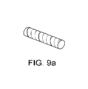
[0057] Figure 9a is a schematic perspective view of a marker according to
another embodiment of the
present disclosure;
[0058] Figure 9b is a schematic side view of the marker of Figure 9a;
100591 Figures 10a to 10c are graphs of sense distance (mm) vs pitch (mm) for
1.3mm diameter markers,
1.15mm diameter markers and 1.0mm diameter markers respectively; and
[0060] Figures 11 to 19 show further various possible marker configurations
according to the present
disclosure.
CA 03234906 2024-4- 12
WO 2023/079292 PCT/GB2022/052779
-9-
1100611 Figure 20 shows a detection system for locating a marker according to
the present disclosure.
Definitions:
[0062] Unless defined otherwise, all technical and scientific terms used
herein generally have the same
meaning as commonly understood by one of ordinary skill in the art.
[0063] Magnetic .flux density (B) is a vector quantity measuring the strength
and direction of the
magnetic field around a magnet or an electric current.
[0064] Magnetic field strength, tilso known as magnetizing field (H) is a
vector field that describes the
magnetic influence of an external magnetic field on moving electric charges,
electric currents, and
magnetic materials.
[0065] Coercivity is the magnetizing field (H) needed to demagnetize a
ferromagnetic material
completely.
[0066] Hard magnetic materials have a high coercivitv. They are also referred
as permanent magnets.
[0067] Solt magnetic materials have low coercivitv. They are easily magnetised
and demagnetised.
[0068] Magnetisation, also known as magnetic polarisation (7V1) is a vector
field that expresses the
density of permanent or induced magnetic dipole moments in a magnetic
material.
[0069] Saturation of induction is the state reached when an increase in
applied external magnetic field H
cannot increase the magnetization M of the material further. In this state,
the total magnetic flux density
that results is called the saturation induction (Be), and the magnetisation is
the saturation magnetisation
(Ms).
[0070] Initial susceptibility (x) is a measure of how much a material of
infinite extent will become
magnetised in a small applied magnetic field. It is defined as x = M 1H for
small H, or equivalently x =
dM
dH1H=0*
[0071] Apparent initial susceptibility (xam,), also known as effective
susceptibility, is the initial
susceptibility for a material of specific geometry in a small applied magnetic
field. That is, it is x after
taking into account the demagnetisation factor (see below).
[0072] Magnetic permeability (u) is the measure of a material's resistance
against the formation of a
magnetic field, where y = B/H.
[0073] Relative magnetic permeability (Ur) is the ratio of magnetic
permeability to the permeability of
free space (110), that is Ur = 11/110
CA 03234906 2024-4- 12
WO 2023/079292 PCT/GB2022/052779
- 10 -
[0074] A.ferromagnetic material has a variable relative permeability (jur)
that increases relative to the
magnetic field and up to a maximum. Many ferromagnetic materials have a
maximum relative
permeability that can exceed 100,000.
[0075] A paramagnetic material has a constant relative magnetic permeability
GO which is slightly
more than 1.
[0076] A diamagnetic material has a constant relative magnetic permeability GO
slightly lesser than 1.
Diamagnetism causes a repulsive effect by creating a small magnetic field in
opposition to an externally
applied field.
[0077] Initial relative magnetic permeability (i..tr,i) is the value of it,
for small H, and is related to the
initial susceptibility by = 1 + x.
[0078] Apparent relative magnetic permeability (ptapp) is the relative
magnetic permeability of a
material of specific geometry. That is, it ispi- after taking into account the
demagnetisation factor.
[0079] Demagnetising field, also known as stray field is the magnetic field
(H) generated by the
magnetisation (M). It gives rise to shape anisotropy in ferromagnets with a
single magnetic domain, and
to magnetic domains in larger ferromagnets.
[0080] Demagnetisation factor is a number that describes the strength of the
magnetic field produced by
an object of specific geometry, compared to an object of infinite extent. It
must be used in order to
determine the demagnetising field. An arbitrarily shaped magnetic object has a
total magnetic field that
varies with location inside the object and can be quite difficult to
calculate. This makes it very difficult to
determine the magnetic properties of a material such as, for instance, how the
magnetisation of a material
varies with its shape and with the magnetic field.
[0081] Magnetic anisotropy describes the variation of magnetic properties
depending on the material
orientation, relative to an externally applied magnetic field.
[0082] The magnetic moment, also known as magnetic dipole moment, is a vector
quantity that describes
the magnetic strength and orientation of a magnet or other object, such as an
electric current loop, that
produces a magnetic field H.
[0083] MRI metal artefacts are distortions of the MR image characterised by a
region of signal void
(black) or bright fringing in the vicinity of a metal object. They occur at
interfaces of tissues and metal
with different magnetic susceptibilities, which cause local magnetic fields to
distort the external magnetic
field. "[his distortion changes the precession frequency in the tissue leading
to spatial mis-mapping of
information..
CA 03234906 2024-4- 12
WO 2023/079292 PCT/GB2022/052779
- 11 -
Detailed Description
[0084] The present disclosure relates to an improved magnetic marker that
allows for surgical guidance
and provides a small enough MRI artefact (preferably less than 2cm) so as to
allow effective radio
diagnostics. It has been surprisingly found that using thin wires of
ferromagnetic material as defined
herein, having a high length to diameter ratio (as defined above) of greater
than 50, preferably at least
about 500, more preferably at least 650, at least 750 or at least 1000, and
low volume of less than about 1
x 10-1 m3, a marker is created that provides a satisfactory sensing
performance, balanced with a small
MRI artefact. The markers of the present disclosure may be further improved by
selecting ferromagnetic
material with a low saturation induction which may further limit the MRI
artefact size. The markers of
the present disclosure may be further improved by selecting a ferromagnetic
material with a high initial
permeability which may improve sensing performance. Various shapes for such
markers, which provide
an improved isotropy of magnetic susceptibility, have also been developed.
[0085] 'Artefacts' can be produced on an MRI image when an object changes the
magnetic fields in an
MRI machine. Thus, a marker of a ferromagnetic material will produce a
significant artefact, reducing
their appeal for use as a long-term marker for patients undergoing treatment
such as neoadjuvant
therapies prior to surgical excision. The artefact is predominantly generated
by the component of the
magnetic field generated by the ferromagnetic object (By) that is in the same
direction as the main field
produced by the MM machine (here referred to as the y-axis). The effect of By
is to shift the local Larmor
frequency of protons near the object, and if that shift is large enough, those
protons will not appear in the
correct slice reconstructed by the MRI machine. That is, points at which 1Byl
Bcrit do not appear in the
expected slice, where Bõit is the magnitude of the y-component of the magnetic
flux density B at which
a voxel is mapped to a different slice, and the value of which depends on MRI
scanning parameters.
[0086] At distances large compared to the object, the field produced by a
ferromagnetic object can be
described by the dipole model. Along the axis of magnetisation, under that
model the magnetic flux
Yon
density is given by B = , where m is the magnetic dipole moment of the
ferromagnetic material and
27ry-
y is the distance from the object to the point of interest. In an MRI machine,
a ferromagnetic object will
typically be saturated, so its magnetic dipole moment is given by m = MV =
¨itBs V. Combining the
equations gives BmRi = Bl.rsylc, where Bmarker,MRI is thc field produced by
the ferromagnetic material
when in an MM field. That is, if B is the total field and Bo is the field
applied by the IVIRI machine, then
B = Bo + Bmarker,MRI = Therefore, it has been found that the strength of the
magnetic field from the
ferromagnetic object in an MRI machine is dependent on the volume of
ferromagnetic material, its
saturation induction and the distance away from it.
[0087] If we now consider the edge of an MRI artefact, then at that point
Bmarkõ,MRI = Bcrit, and y
describes the distance from the centre of the artefact to its edge. At that
point, using the equation above,
CA 03234906 2024-4- 12
WO 2023/079292 PCT/GB2022/052779
- 12
Ets V V
we obtain y3 = BV , and so y ¨ 27r) . If we define the -diameter"
of an artefact along the y-
Bcrit 21T Bcrit
axis (although it may not be circular) as a measure of its extent as
Daitefacty = 2y, then it follows that
1
Dartefact,y 2 ' -
Bcrit 2n
[0088] In summary, the saturation induction (B1) and volume of magnetic
material (V) determine the size
of the. MRI artefact, as follows:
( Bs. V
Dartefact y = 2 ___________________________________
crit 2Th )
[0089] This constraint on the maximum volume of magnetic material that you can
use makes it difficult
to make a marker from a magnetic material that has an effective sense
distance, good isotropy and a small
artefact. The markers of the present disclosure address this problem.
[0090] To apply this finding to a ferromagnetic material that would retain a
good magnitude of magnetic
field under sensing, the susceptibility in relation to the shape has also been
studied.
[0091] As above, the magnitude of the magnetic flux density, B, from a
ferromagnetic object along the
axis of magnetization is given by B = 11(71 = In a magnetic field much weaker
than that produced by an
2my3
MRI machine, such as that produced by magnetic susceptometry probes such as
the one described in WO
2014/140566 Al, the magnetisation of the material is M = XappH, where xapp is
the apparent initial
susceptibility. By definition, its magnetic dipole moment, m = MV, so that m =
XappHV , and this in turn
gives the following expression for the magnetic field produced by an object
when stimulated by a weak
field:
B = lioXapp1117
27-t-y3
[0092] This last equation demonstrates that the strength of the sense response
will be proportional to the
(a) the volume of magnetic material (V); (b) the strength of the applied field
(H); and (c) the apparent
susceptibility of the magnetic material (xapp). This last quantity will be
much larger for a long, thin
magnetic material as illustrated in Figure 1 of the accompanying drawings. The
equation also shows that
the strength of the sense response will reduce with distance away from the
marker (in inverse proportion
to the distance cubed).
[0093] Certain shapes of markers comprising ferromagnetic material have been
found to be unsuitable
for purpose. For example, a sphere cannot give the expected artefact size for
the needed sense distance as
the susceptibility will be low for any diameter. It has been found that for an
MRI artefact with a diameter
below lOmm under a 1.5T MR1 field, the diameter of the sphere cannot exceed
0.18mm which would be
too small to handle during manufacturing and to be seen by the surgeon after
extraction of the tumour. On
CA 03234906 2024-4-12
WO 2023/079292
PCT/GB2022/052779
- 13 -
the other hand, to sense beyond 40mm, the sphere would need to exceed 1.1mm
which would give an
artefact much bigger that what would be considered acceptable.
Example 1: Physical Properties of a Marker according to the
disclosure.
[0094] As mentioned above, during sensing a marker is subjected to a small,
oscillating field. Its
magnetic response is described by its permeability, it, or susceptibility, x
(where = 1 + x). If the
initial susceptibility or the initial relative permeability is known, it is
possible to predict the magnetic
response of the marker. It has been determined that the apparent initial
susceptibility depends on the
material, its shape and the frequency of the applied field.
[0095] It was deduced that increasing a magnetic material's aspect ratio (L/D,
where L is the length of a
cylinder of the material and D is its diameter) dramatically increases its
sense performance in the
direction of its central axis. This is illustrated by Figure 1: as the ratio
L/D increases, so does the apparent
permeability ;Lapp of the object, which in turn increases the distance at
which it can be sensed. This
phenomenon is due to the demagnetisation effect, which may be understood
intuitively as follows: if an
object is substantially perpendicular to an applied magnetic field, the
microscopic magnetic dipole fields
produced in the object will mostly act to cancel each other out. Conversely,
if the object is substantially
parallel to the applied magnetic field (as for a long, thin rod aligned with
the field), the microscopic
dipoles produced in the object will interact constructively, thereby creating
a stronger magnetic field,
which in turn allows the marker to be detected more easily.
[0096] Under an AC magnetic field, an additional phenomenon takes place: eddy
currents induced in the
material then create an additional magnetic field that partially shields the
material from the external field,
thus reducing the sense performance. Eddy currents can make a significant
difference when the object
subjected to the field has a large area perpendicular to the field. In
contrast, for very thin rods (0 ¨ 50
lam), eddy currents actually do not significantly affect the sense performance
of magnetic wires. For
significantly thicker rods (0 ¨ 500pm), eddy currents are significant if L/D >
1. Therefore, in order to
reduce or remove the effect of eddy currents on the sense performance of a
magnetic wire, it is preferably
that the wire is thin.
[0097] For cylinders, aspect ratio is the most important factor.
[0098] For rods of aspect ratio L/D < 10, initial relative permeability
(1.1,,i) makes little difference as
long as it is >1,000, as evident from Figure 1. However, for rods of greater
aspect ratio, a higher initial
relative permeability is beneficial: for example, for a rod of L/D = 400,
increasing ictr,i from 1,000 to
50,000 increases Papp approximately 7-fold.
[0099] The magnitude of the ferromagnetic material's magnetic field induced
under MR1 determines the
size of the MM artefact. During MM, the marker is subjected to a large,
constant field and magnetization
saturates at B, = yoM, (the "saturation induction"). The range of B, for most
ferro-magnetic materials is
CA 03234906 2024-4- 12
WO 2023/079292 PCT/GB2022/052779
- 14 -
¨0.25-1.5 T. Thus, the MM field (1.5-3.0 T) is strong enough to saturate these
materials so the
magnetisation of a ferromagnetic marker in MM can be calculated simply as
M,B., = Bs/go. So, to
minimize the artefact size, a material with a low B is required.
[0100] This is illustrated in Figure 2 of the accompanying drawings.
[0101] This leads to a limited range of properties that need to be met by a
marker to provide a
satisfactory sensing response and a reduced MM artefact. A minimal volume of
magnetic material
should be used, the aspect ratio should be high, and preferably the marker
should have a high apparent
initial susceptibility, and the material should have a low saturation
induction, preferably less than about
1.0 T.
[0102] It has been surprisingly found that a thin long wire of ferromagnetic
material could provide the
required properties of an apparent susceptibility superior or equal to 1,000.
Figure 3a is a simulation
confirming the feasibility of a straight wire that is detectable at useful
range while showing a small MM
artefact. The dotted line shows, for each wire diameter, the minimum length
required for it to be sensed at
40mm, assuming the wire material has susceptibility x = 72,000. The dot-dashed
line shows, for each
wire diameter, the maximum length permitted such that the MM artefact of the
wire has a diameter less
than lOmm, assuming the wire material has a saturation induction B., of 1 T.
The hatched region in the
upper-left comer of the graph corresponds to the wire dimensions that
simultaneously are detectable at
40mm or farther, and produce an MM artefact of diameter lOmm or smaller. This
figure shows that the
wire length must be much greater than the wire diameter to satisfy both of
these conditions
simultaneously.
[0103] Figure 3b shows the same simulated data as Figure 3a, but over a
narrower range of wire
diameters, and for more sense distances and saturation inductions. The dotted
and dot-dashed lines have
the same meaning as in Figure 3a. The dashed and solid lines correspond to
additional values of sense
distance and saturation induction as indicated in the legend. This figure
shows that a wide range of wire
dimensions can be used if one accepts a lower sense distance (30mm rather than
40mm); or if the material
has a lower saturation induction (0.5T rather than IT).
[0104] A low saturation magnetization gives a small ferromagnetic dipole in
the MM scanner, and a
high initial permeability means a small volume of material will give a large
sense response on a probe
such as magnetic susceptometry probes such as the one described in WO
2014/140566 Al, the contents of
which are incorporated herein by reference.
CA 03234906 2024-4- 12
WO 2023/079292 PCT/GB2022/052779
- 15 -
Effect on
Change in marker Effect on MRI susceptometry sensing
characteristic artefact response Conclusion
Reduced volume of Reduces artefact Reduces sensing Reducing
volume reduces
marker material (proportional to response (proportional
artefact size but reduces sensing
Vi") to V) response by a
greater factor
Reduced material Reduces artefact Minimal impact Saturation
induction is
saturation induction (proportional to preferably
minimised to reduce
(B) B113) MRI artefact
without affecting
sensing
High initial No impact Increases sensing Initial
permeability is preferably
permeability of response up to 1.1,= at least
1000 for adequate
marker material ¨1000 sensing
Increased length to No impact (if Increases sensing
Length:diameter ratio should be
diameter ratio of volume stays the distance (proportional
maximised for increased sensing
marker material (i.e. same) to apparent for a given
volume of material
increased apparent susceptibility xcipp) (or same
sensing with reduced
susceptibility) volume)
[0105] The sense response under a magnetic susceptometry probe field and the
MRI artefact of a
ferromagnetic material depend on different variables. It has been recognised
that in a small oscillating
field, such as that produced by SentimagTM, which is commercially available
from Endomagnetics Ltd,
UK, the sense performance depends almost exclusively on aspect ratio and
volume, with a weaker
dependence on the relative initial permeability, I1r,i (the initial gradient
of the B-1,10H curve). In contrast,
the magnitude of magnetic field produced by the marker in an MRI machine, and
hence the MRI artefact
size, depends on the saturation induction B., and volume of material. This
means that it is possible to
produce the required small MRI artefact with a very thin piece of low-
saturation-induction ferromagnetic
material that can still be sensed at a satisfactory distance, as demonstrated
in Table 1 below for a material
with x = 72,000 and B., = 0.5 T:
Wire Wire volume
Wire 0 length (mm3) Simulated MRI Simulated axial
sensing
(Am) (mm) artefact 0 (mm) distance (mm)
685 1.6 0.590 40 30
198 2.5 0.077 20 30
122 2.7 0.032 15 30
62 3.1 0.009 10 30
CA 03234906 2024-4- 12
WO 2023/079292
PCT/GB2022/052779
- 16 -
Table 1
[0106] A marker having a large aspect ratio, preferably having a length to
diameter ratio of at least 50,
more preferably at least 60, especially at least 100, and more especially at
least about 500, with a low
total volume, such as one having a length of at least 3mm, preferably being at
least 6mm long with a
diameter less than 100tim, preferably having a diameter equal to or less than
50tun, especially equal to or
less than 30]..tm piece of low-saturation-induction ferromagnetic material was
found to be sensed
adequately while producing a low MRI artefact.
[0107] This is demonstrated in Figures 3a and 3b of the accompanying drawings,
which demonstrate
MRI performance depending upon the rod length and diameter. For a given Bs,
anything below the
contour gives an acceptable artefact
Example 2: Study into Preferred Materials for a Magnetic Marker
according to the disclosure.
[0108] The marker described in Example 1 was further investigated to allow
selection of the preferred
magnetic materials that would produce the required high initial relative
permeability itr,i > 1000, be
formable into very thin strips or wire to allow the large aspect ratio but low
volume to be configured, and
having a low saturation induction Bs, ideally having a low B, of less than 1
T.
[0109] Preferred materials that possess the required characteristics were
found to be particular metals,
amorphous metals and ceramic ferrites, preferably cobalt-based amorphous
metals such as those sold
under the trade names Yshield MCE61 TM, Metglas 2705MTm and Metglas 2714ATM;
Manganese-Zinc
ceramic ferrites such as those sold under the trade names Fair-Rites 31Tm,
76TM and 78TM; Nickel-iron-
based soft ferromagnetic alloys such as those sold under the trade names Mu-
metal, Permalloy 80,
Permalloy C, Permalloy and Supermalloy; Nickel-Zinc ceramic ferrites such as
those sold under the trade
names Fair-Rites 151m, 201-m, and 431m; and more preferably Cobalt-based
amorphous metals such as
YshieldTM and Metglas 2714ATM.
[0110] Ceramics, although having a low saturation induction, are less easy to
form into wire or flat wire
and therefore are less suitable for a marker according to the disclosure.
[0111] Figure 4 is a plot of saturation induction against initial relative
permeability for a wide variety of
different materials. The materials which may form suitable markers are
contained in the top left hand
region of the graph, demonstrating low saturation induction and high relative
initial permeability.
Example 3: Investigation into Optimized Design for a Magnetic Marker
according
to the disclosure.
[0112] The thin long wire marker discussed in relation to Examples 1 and 2
provides the required initial
relative permeability jt1 > 1000, preferably > 10,000, large aspect ratio but
low volume and has a low
saturation induction B5. However, this type of marker has a high anisotropy
ratio, demonstrating a strong
sense response only in the direction of its axis.
CA 03234906 2024-4- 12
WO 2023/079292 PCT/GB2022/052779
- 17 -
[0113] From a practical perspective, during surgery to detect the marker using
a magnetic probe as
described in W02014/013235, high anisotropy is undesirable: the magnetic
signal at a constant distance
will vary depending on the orientation of the marker relative to the probe and
make the marker appear to
be closer when approaching from some orientations and further away from
others. Minimising the
anisotropy for the implanted marker improves the surgeons' ability to localise
the marker by making it
more intuitive and increases the surgeons' ability to remove a safe margin of
tissue around a lesion. An
anisotropy ratio of 1 is the ideal, giving a uniform response from any
direction. However, in practice this
is challenging to achieve within the geometric constraints of delivery through
a small needle. An
anisotropy ratio of less than 7 (i.e. between 1 and 7), preferably less than 5
and more preferably less than
3 is desirable. Because the magnetic sense response depends strongly on
distance (under certain
conditions, approximately in inverse proportion to its sixth power),
conversely the calculated distance
depends relatively weakly on the magnetic sense response. Therefore an
anisotropy ratio of less than 2 is
close enough to the ideal for practical use, a ratio of 5 may not be
distinguishable in practice from
isotropic, and a ratio of 7 may provide adequate uniformity.
[011411 Two ways have been indentified to increase the axial sensing and
increase isotropy of magnetic
susceptibility. It was also desirable to provide a marker that does not need
to be unpacked at the injection
site since deployable concepts need to have a consistent unpacking mechanism
to allow for accurate
placement and a full unpacking to give the necessary sensitivity and isotropy.
Thus, having a marker that
does not need to be unpacked at the injection site would also provide a
significant improvement over the
prior art. To achieve this, a marker may comprise a multitude of small
ferromagnetic rods using the wire
of Example 1 encapsulated within a single cylinder where all axes would be
covered. However, this type
of marker still faced several challenges in terms of detection sensibility (as
short rods are expected to
have a low axial susceptibility and some destructive interactive effects), MR1
artefact (as the complexity
of the magnetic dipoles would be at the utmost complexity to estimate), safety
and regulation and
manufacturing process for encapsulation of the rods and consistency.
[01151 Thus, further configurations were investigated for optimized markers
according to the disclosure.
For a given artefact size, it has been determined that there is a constraint
on the maximum volume of
magnetic material you can employ for use in a marker. The use of a material
having a low saturation
induction B., will enable more material to be used. The wire's diameter will
dictate the total length of
wire available and its relative permeability and the aspect ratio of the wire
can then be used to calculate
the sense response.
[0116] The key variables have been identified that can be modified to improve
the design of marker as
the total wire volume and the wire length as the strongest dependence on the
artefact diameter is the
diameter of the wire and therefore the latter does not offer much variability.
If a design consists of a wire
diameter D, the permitted length of wire L is:
CA 03234906 2024-4- 12
WO 2023/079292 PCT/GB2022/052779
- 18 -
1 Bcrit
L ¨ D3 = - = -
artefact, y D2 Bs
wire
[0117] Initially, an arrangement containing multiple rods of the thin wire
arranged in different
orientations was considered to enhance the anisotropy of the marker. It has
been unexpectedly found that
neighbouring rods can have positive or negative interactions on the total
dipole moment, as demonstrated
in Figures 5a, 5b and 5c of the accompanying drawings.
[0118] Figure 5a shows that parallel rods placed 0.5mm apart from each other
decrease the dipole
moment by 5% for 50nm diameter rods and by 10% for 100 lam diameter rods. On
the contrary and as
seen on Figure 5b, two identical rods placed perpendicularly and where the
ends are separated by a rod
diameter length will increase the total dipole moment by 5%. Additionally,
perpendicular rods show a
smaller decrease of their dipole moments if offset axially as seen in Figure
Sc.
[0119] Based on these findings, marker configurations with closely spaced
parallel rods were excluded
as markers of the disclosure. However, satisfactory markers forming
embodiments of the disclosure were
configurations where it is possible to offset the placement of these parallel
rods, as shown in Figure 5c.
Further embodiments are shapes where perpendicular rods could be placed end on
end.
[0120] Preferred spacings for the rods are at least one diameter space apart.
[01211 The rods provided in the required configuration may be encapsulated in
a cylindrical housing as
is known in the art. For example, the marker may be packaged within other
materials to ensure they are
biocompatible to prevent a reaction with body tissue, and robust or a coating
may be applied to the
marker. The marker may be encased in a tube, for example made from Nitinol,
titanium, stainless steel or
other biocompatiblc alloys, the material preferably being non-magnetic and
having a relatively low
conductivity. Suitable coating materials include a polymer coating, such as
FEP, Pary-lene, PTFE, ETFE,
PE, PET, PVC or silicone or an epoxy based encapsulant.
[0122] Given the difficulty to assess magnetic dipole moments in a complex
structure, a methodology
has been developed to establish how different shapes behave and interact
together. The findings are
summarised in Figure 6.
[0123] It was concluded that larger aspect ratio designs, either longer rods
or larger rings, will produce a
design with a much better sense performance to MRI artefact. In this respect,
per unit volume, 5mm long
rods were found to be around eight times better than lmm long ones and per
unit volume, a ring was
found to be better than two perpendicular rods. Ring or coil-based designs
were also determined to be
better than two perpendicular rods to produce sense response in two
directions.
[0124] In this respect, referring to Figure 6 of the accompanying drawings,
the quantity mz/V indicates
how much sensing response the marker produces per unit volume. Although the 5
mm straight rod
produces a stronger response per unit volume than the ring (mz/V of 54 for the
rod vs 42 for the ring), the
rod produces a magnetic response only along its axis, while the ring does so
in the two dimensions
CA 03234906 2024-4- 12
WO 2023/079292 PCT/GB2022/052779
- 19 -
covered by its plane. Therefore the correct figure of merit for the ring is 2
x 42 = 84, i.e. ¨50% better
than the rod.
[0125] Figure 7 of the accompanying drawings illustrates the configuration of
a number of markers
according to embodiments of the present disclosure that were found to produce
the required low MM
artefact with good sense response in multiple directions. Figure 7 provides
the sense distance at 200 mA
for an artefact diameter of diameter lOmm. The material parameters are: I1r =
72,000, B, = 0.55 T and
the diameter of the wire is 30 JAM, with a maximum total length of 21mm.
[0126] This figure also highlights the preferred embodiments for this
disclosure which are the helix
shape, rings and offset parallel or perpendicular rod arrangements. These
provide the best performance
per volume of material used.
Example 4: Further Investigations in relation to helical coil marker
according to
examples of the present disclosure.
[0127] Given the ease of manufacture of a helix shape, the optimisation of
this shape was further
investigated as a preferred marker according to the disclosure.
[012S] It was demonstrated that two types of different helical designs produce
an acceptable sense
response, both in terms of minimum sense distance and isotopy. As shown in
Figures 8a to 9b
respectively, these are (i) single helix combined with one longitudinal wire
aligned parallel to the axis
core (Figures 8a and 8b) and (ii) a multiple helix, consisting of a double or
triple helix (Figures 9a and
9b). In Figure 8a and 8b, the longitudinal wire is aligned parallel and co-
axial with the axis core. In an
alternative arrangement the longitudinal wire is located at a side of the
helix rather than co-axial with the
axis core.
[01291 A marker with a single helix design gets its transverse response from
its helical coil, and the
majority of its axial response from its axial rod, while a marker with the
triple helix design uses a larger
pitch to get both its transverse and axial response from its helical coil (the
larger pitch means the coils
point more towards the axial direction). In the context of triple and other
multiple hexices, the term
"pitch" as used herein means the pitch of each constituent individual coil of
the multiple helix, unless the
clear context implies otherwise.
[0130] The sense distance has been predicted using a combination of standard
physics simulation
software (COMSOL), custom computer models and experimentation, for one or
several axial rods used
and for two diameters, as shown in Table 2 below.
CA 03234906 2024-4- 12
WO 2023/079292 PCT/GB2022/052779
- 20 -
030jam Co-Fe amorphous
015 m Co-Fe amorphous metal
Length of axial rod metal predicted sense
predicted sense distance (mm)
(mm) distance (mm)
1 rod 2 rods 3 rods 4 rods 1 rod 2 rods
4 27 31 34 35 30 35
30 34 37 38 33 38
6 32 36 39 41 36 40
7 33 38 41 43 38 43
9 42
Table 2
[0.131] According to the present disclosure, it is desirable to minimise the
amount of material used to
minimise the MM artefact and, by combining this with the results of the
simulation, it can be concluded
that it is desirable to use a smaller diameter and one longer rod rather than
two shorter ones.
[00100] For a single helix design with a longitudinal wire aligned parallel to
the axis of the core (Figure
8a and 8b), it has been determined that it is necessary to use the thinnest
wire possible (see Example 1
above) with the maximum length of wire possible. One should also maximise the
diameter of the coil to
provide a stronger transverse sense response for the same volume of material,
as illustrated in Figure 6.
Figure 8b shows an optional housing or tube 80 in dotted lines located around
the helical coil. The marker
may be encased in a tube, for example made from Nitinol, titanium, stainless
steel or other biocompatible
alloys, the material preferably being non-magnetic and having a relatively low
conductivity. Suitable
coating materials include a polymer coating, such as FEP, Parylene, PTFE,
ETFE, PE, PET, PVC or
silicone or an epoxy based encapsulant.
[0132] The graph of pitch against transverse sensing distance surprisingly
does not show a sharp peak
around the optimal value, and the pitch must be balanced with the axial
sensing increase to reach a sweet
spot. Figures 10a to 10c show that the pitch that maximizes transverse sense
performance approximately
equals the helix diameter ¨ this is the optimal pitch for the single helix
design where helical coil must
only produce the transverse sense response and the axial component comes from
the axial wire. While the
pitch that produces isotropic sense performance approximately equals 1.6x the
helix diameter ¨ this pitch
is useful for the multiple helix designs that exclude the axial wire, and so
both the axial and transverse
sense response must be produced by the helical coil. Figures 10a to 10c
illustrate the sense distance (mm)
against pitch (mm) for lmm diameter markers, 1.15mm diameter markers and 1.3mm
diameter markers
respectively.
[0133] The other design option of having multiple helices to avoid the need
for the axial rod was
investigated further. Table 3 below shows that with the same total length of
wire, the total number of
turns per helix increases between one helix with a rod and a double helix or
triple helix without rod.
CA 03234906 2024-4- 12
WO 2023/079292 PCT/GB2022/052779
-21 -
Marker No. of Pitch Axial Turns Total Total
Length
Size OD helices (mm) wire per helix number length of of
x L (mm) of turns wire marker
(mm) (mm) (mm)
1.15x Single 1.0 8 8.0 8.0 38.0
8.0
8.0
1.15x Double 1.7 n/a 4.8 9.6 38.0
8.0
8.0
1.15 x Triple 2.4 n/a 2.8 8.4 38.0
8.0
8.0
Table 3
[0134] To keep the same marker length and diameter, the double helix and
triple helix have higher pitch
which was expected to give better axial detection but surprisingly and as
shown in Table 4 below, the
transverse detection was only slightly affected and even more surprisingly it
has been found that the
transverse detection increased. A major unexpected finding was also the non-
destructive effect on the
susceptibility of having helices interlaced in close proximity with one
another, without touching.
[0135] As a conclusion, it has been found that for a given amount of material
and marker length, a single
helix will present a short pitch and may require combination with a
ferromagnetic rod. Alternatively, a
double or triple helix incorporated into a marker with the same amount of
material for the same length
will require the helices to be stretched so that the pitch increases and this
helps move the coils in a more
axial direction but surprisingly does not decrease the transverse detection.
[0136] If a stronger sense performance is required in a more compact shape, a
higher order helix may be
used to provide more coils per unit length. However, if too many coils are
closely packed together,
(spacing less than I x the diameter of the coil), they will start to
destructively interact.
[0137] Marker size for all cases in Table 4 was diameter of 1.15mm and length
of 8.0mm.
No. of Pitch Axial Turns Total Total Length Transverse Axial
sense
helices (mm) wire per number length of sense distance
(mm) helix of turns of marker distance
wire (mm) (mm)
(mm)
Single 1.0 8 8.0 8.0 38 8.0 30 34
Double 2.0 n/a 4.0 8.0 34 8.0 30 31
Triple 3.0 n/a 2.7 8.4 38 8.0 30 35
Triple 2.6 n/a 3.1 9.2 41 8.0 31 34
Triple 2.0 n/a 4.0 12.0 51 8.0 33 33
CA 03234906 2024-4- 12
WO 2023/079292 PCT/GB2022/052779
- 22 -
Table 4.
[0138] As noted from Table 4 above, decreasing the pitch and increasing the
number of turns will
increase the transverse sense performance but will decrease the axial sense
performance. It will also
increase the total length of wire used which will increase the MRI artefact
size. Increasing the pitch and
decreasing the number of turns will decrease the transverse sense performance
but will increase the axial
sense performance. It will also decrease the total length of wire used which
will decrease the MRI artefact
size. There is an optimum pitch to produce an isotropic sense performance for
each type of multi helices
marker (e.g. for triple helices it is ¨2.0mm pitch for a 1.15mm diameter
marker using 15um Co-Fe
amorphous metal wire.)
Example 5: Investigation into alternative Ferromagnetic Materials
for Markers according to the
present disclosure.
[0139] The markers hereinbefore disclosed all use thin wire as described in
relation to Example 1 above
to produce an optimized design of marker. However, preferred magnetic
materials that would produce
the required high initial relative permeability tir,i > 1000, preferably >
10,000, and have a low saturation
induction Bs may also be formable into strips, flat wires with an oblong
section for providing markers
according to the disclosure.
[0140] For example, Table 5 below illustrates iron metal alloys having 1.tr,j>
15,000 that meet the
requirements for a marker according to the disclosure and may be provided in
rolled sheet form prior to
being cut into wires or strips.
Material (and type) Form Bs lir Curie temp Material
Performance
(T) ( C) size (p.m)
indicator**
Co-Fe amorphous Wire 0.6 15,000 300 30
1
metal
(Co-Fe amorphous
metal)
Metglas 2714A Sheet 0.57 72,000 225 15
4.2
(Cobalt-based
amorphous metal)
ULTRAPERM Sheet 0.74 300,000 360 20 1.8
(Ni-Fe metal alloy)
Supermalloy Sheet 0.65 30,000 460 (20) (2.1)
(Ni-Fe metal alloy)
Table 5
(**) Indicator of the amount of material available for a given artefact size.
More material should give a
stronger signal response.
CA 03234906 2024-4- 12
WO 2023/079292
PCT/GB2022/052779
- 23 -
[014.1] Marker designs can be created from these thin sheets using known
manufacturing techniques,
such as etching or laser cutting. These manufacturing techniques would aim to
create wires that may or
may not result in a flattened shape. In the case of flattened wire, the
diameter described in other sections
of this application essentially corresponds to the average radial length of
the wire.
[0142] It is readily apparent from the above description that the implantable
markers according to the
disclosure provide small ferromagnetic markers with good isotropy of magnetic
susceptibility, sense
distance and showing a small MR1 artefact.
Example 6:
Use of Markers according to the disclosure in the monitoring and treatment
of
breast cancer.
[0143] The markers according to the present disclosure are particularly
suitable for the monitoring and
treatment of breast cancer, enabling tracking of the size of the tumour during
preliminary ncoadjuvant
therapy with the aim of shrinking the size of the tumourbelow 2cm long or to
at least a size that is
sufficiently small compared to the overall (BCS).
[0144] Patients that present a breast cancer tumour of more than 2cm but less
than 5cm and which has
not spread further than the lymphatic nodes in close proximity (often
categorised as "Stage 2" breast
cancer) can be offered BCS but this generally requires neoadjuvant therapy to
shrink the tumour to
around 2cm or less. In parallel with this, the healthcare professional will
also need to assess the exact
nature of the tumour, typically requiring a biopsy to be performed to sample
some of the tumoral tissue.
[0145] A marker according to the present disclosure can be placed in the
cavity created by the tissue
sampling in order to locate the tumour using a magnetic susceptometry probe,
such as the probe described
in WO 2014/140566 Al. This enables the tumour to be located during future
assessments of tumour
progression and/or for ablation of the tumour. A susceptometry detection
system for locating a marker is
shown in figure 20, where a marker 20 according to the present disclosure is
shown, along with a
magnetic susceptibility probe 22, the probe 22 including a drive coil 24
arranged to to excite the marker
with an alternating magnetic field, and a detector 24 arranged to receive the
signal from the sense coil. A
magnetic field generator 28 is arranged to drive an alternating magnetic field
through the drive coil 24,
and the detector 24 is arranged to detect one or more harmonics of the drive
frequency in the received
signal.
[0146] The marker of the disclosure also enables the tumour response to
adjuvant therapy to be tracked
by periodic examination, for example under MM, due to the size of the artefact
created under MM field
by the marker being kept to a minimum, ideally not more than 2cm long. In this
respect, the marker
should not interfere with the assessment of tumour size while it is too big
for BCS (essentially around
2cm but possibly more).
[0147] Thus, the markers of the disclosure are particularly suitable for the
protocol commonly pursued
by healthcare professionals when tracking breast cancer progression under MM
due to their low induction
CA 03234906 2024-4- 12
WO 2023/079292 PCT/GB2022/052779
- 24 -
saturation and low mass per volume which allows a significant reduction in the
size of the MM artefact.
Once the tumour has shrunk to a size that allows BCS, the healthcare
professional is able to locate the
tumour by means of the marker. The markers can be detected by a magnetic
susceptometry probe that is
positioned at least 3cm, up to 5cm, away thereby enabling a tumour which may
be a few centimetres
below the surface of the skin to be located. This enables the healthcare
professional to determine the best
path to access and remove the tumour by ablation prior to incision of the
tissue.
[01481 In Figures ha and lib, and 19, the marker 6 comprises a length of
magnetic marker material
bent to describe three or four edges 6a, 6b, 6c of a tetrahedron. By so doing,
the harmonic signal response
of the marker is more uniform from any given direction of sensing. In a
further aspect, the radii of the
bends 6d may be configured, e.g. by making them larger, to allow the marker to
be packed into an outer
tube more easily prior to deployment.
[0149] In Figure 12, the marker comprises a length of magnetic marker material
bent into a portion of a
circle 6e, with one end 6f bent radially towards the centre and then bent
substantially at 900 out of the
plane of the circle be to form a portion 6g along or parallel to the axis of
the circle.
[0150] In Figure 13, the marker 6 comprises lengths of magnetic marker
material arranged along three
orthogonal axes x, y and z to form the shape of a Jack' (also known as a
jackstone or knucklebone).
[0151] In Figures 14a and 14b, the marker comprises a length of magnetic
marker material with a
straight central section 6h and two further sections 6i, 6j, one at each end
bent orthogonally from each
other and from the central section. In a further aspect, the radii of the
bends bk may be larger to allow the
marker to be inserted into an outer tube more easily.
[0152] In Figure 15 the marker 6 comprises a length of magnetic marker
material in the shape of a
circular standing wave, i.e. formed into a uniform wave shape and then bent
round to join the ends and
form a circle in plan view.
[0153] In Figure 16, the marker comprises an elliptical or oval shaped length
of magnetic marker
material 6n with the wire ends 6o joined or close to one another but not
joined. Two portions of the
ellipse or oval at the ends of its longer axis are bent to approximately 900
of the plane of the ellipse. The
bent portions comprise approximately one quarter to one third of the area of
the ellipse or oval.
[0154] In Figure 17, the marker comprises three lengths of magnetic marker
material 6t,6u,6v arranged
orthogonally to each other to form substantially an orthogonal tripod or the
vertex of a cuboid. The three
lengths are joined with a joining section 6w that allows the lengths to he
parallel to each other prior to
deployment and then redeploy to form an orthogonal tripod.
[0155] In Figure 18a and 18b, the marker comprises three lengths of magnetic
marker material 6x,6y,6z
arranged to form a tripod with a non-orthogonal angle between the legs of the
tripod. The three lengths
CA 03234906 2024-4- 12
WO 2023/079292 PCT/GB2022/052779
- 25 -
are joined with a joining section 6w that allows the lengths to be parallel to
each other prior to
deployment and then redeploy to form the tripod.
[0156] In one embodiment, the magnetic marker may comprise a wire made of
ferromagnetic material in
the form of a helical coil with the following properties:
Criteria Magnetic marker
Wire length 36 mm
Wire diameter 0.015mm
Total wire length to diameter ratio 2400
Volume of ferromagnetic material 6.4x10 '2m3
Total marker length excluding heat 5 mm
shrink and capsule
Pitch 1.6 mm
Number of coils 3 coils
Core diameter 1.2 mm
Core length 5 mm
Core volume 5.65x10⁻⁹m3
Volume of diamagnetic/ferromagnetic 883
[0157] Preferably the angle between the legs is chosen such that the harmonic
magnetic response is as
uniform as possible from any direction. The tripod is uniform with three
equally spaced legs.
[0158] Whilst the marker of the present disclosure have been described and
illustrated with reference to
particular embodiments, it will be appreciated by those of ordinary skill in
the art that the markers lend
themselves to many different variations not specifically illustrated herein.
[0159] Where in the foregoing description, integers or elements are mentioned
which have known,
obvious or foreseeable equivalents, then such equivalents are herein
incorporated as if individually set
forth. Reference should be made to the claims for determining the true scope
of the present disclosure,
which should be construed so as to encompass any such equivalents. It will
also be appreciated by the
reader that integers or features of the disclosure that are described as
preferable, advantageous,
convenient or the like are optional and do not limit the scope of the
independent claims. Moreover, it is
to be understood that such optional integers or features, whilst of possible
benefit in some embodiments
of the disclosure, may not be desirable, and may therefore be absent, in other
embodiments.
CA 03234906 2024-4- 12