Note: Descriptions are shown in the official language in which they were submitted.
WO 2023/105442
PCT/IB2022/061887
OPTICAL SYSTEM FOR OBTAINING SURGICAL INFORMATION
BACKGROUND
[0001]
Laser and/or illumination probes may be used during a number of different
medical procedures and surgeries. For example, a laser probe may be used
during retinal
laser surgery in order to seal retinal tears. An illumination probe may be
used to provide
illumination to a desired location during a procedure, and may be used in
combination
with a laser probe. In fact, laser and illumination functions may be carried
out by
separate probes, or they may be combined into a single illuminated laser
probe. In either
case, laser and/or illumination light is typically transmitted from a laser
and/or
illumination light source through an optical fiber.
[0002]
Surgical procedures are often performed primarily based on pre-operative
planning as well as the surgeon's past experience. Visualization and data
acquisition
during surgery remain somewhat limited. For example, existing systems lack the
capability to provide the surgeon with information measured in situ related to
spectral
parameters of tissues/structures and/or treatment results that could enable
real-time
adjustment of treatment parameters, e.g., laser power, pulse duration or
frequency, etc.
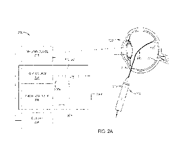
[0003]
Accordingly, what is needed in the art are improved devices for obtaining
surgical information during procedures including an improved laser and/or
illumination
probe.
SUMMARY
[0004]
The present disclosure generally relates to devices for obtaining medical
information, and more particularly, to an optical system for surgical
procedures and
methods of use thereof.
[0005]
In certain embodiments, an optical system for obtaining surgical
information
is provided. The optical system includes a probe housing a first optical
fiber, a light
source, a photoanalyzer, and an optical circulator optically coupled to each
of the first
optical fiber, the light source, and the photoanalyzer. The optical circulator
has a first
1
CA 03236027 2024- 4- 23
WO 2023/105442
PCT/1B2022/061887
port configured to receive source light generated from the light source, a
second port
configured to transmit the source light from the first port to the first
optical fiber, and a
third port. The first optical fiber is configured to emit at least a portion
of the source light
in the first optical fiber from the probe to contact a body structure (e.g.,
an eye, ear, nose,
throat or other body structure), and collect light returning from the body
structure as a
result of the portion of the source light contacting the body structure. The
third port is
configured to transmit the return light in the first optical fiber from the
second port to the
photoanalyzer. The photoanalyzer is configured to determine one or more
spectral
parameters of the body structure based on the return light.
BRIEF DESCRIPTION OF THE DRAWINGS
[0006]
So that the manner in which the above-recited features of the present
disclosure can be understood in detail, a more particular description of the
disclosure,
briefly summarized above, may be had by reference to embodiments, some of
which are
illustrated in the appended drawings. It is to be noted, however, that the
appended
drawings illustrate only exemplary embodiments and are therefore not to be
considered
limiting of its scope, and may admit to other equally effective embodiments.
[0007]
FIG. 1 illustrates a system for providing an illumination light and/or a
laser
light to a surgical target.
[0008]
FIG. 2A illustrates an example optical system for obtaining ophthalmic
information, according to certain embodiments.
[0009]
FIG. 2B illustrates another example optical system for obtaining ophthalmic
information, according to certain embodiments.
[0010]
FIG. 2C illustrates an example optical circulator of the optical system of
FIG.
2A or FIG. 213, according to certain embodiments.
[0011]
FIG. 2D illustrates an example photoanalyzer of the optical system of FIG.
2A or FIG. 213, according to certain embodiments.
2
CA 03236027 2024- 4- 23
WO 2023/105442
PCT/1B2022/061887
[0012]
FIG. 3 illustrates an example method for using ranging data obtained by the
optical system of FIG. 2A to improve safety during vitrectomy procedures,
according to
certain embodiments.
[0013]
FIG. 4 illustrates another example method for using ranging data obtained
by
the optical system of FIG. 2A to provide constant surface illuminance during a
surgical
procedure, according to certain embodiments.
[0014]
FIG. 5 illustrates yet another example optical system for obtaining
ophthalmic
information, according to certain embodiments.
[0015]
FIG. 6 illustrates an example probe that may be used herein, according to
certain embodiments.
[0016]
To facilitate understanding, identical reference numerals have been used,
where possible, to designate identical elements that are common to the
figures. It is
contemplated that elements and features of one embodiment may be beneficially
incorporated in other embodiments without further recitation.
DETAILED DESCRIPTION
[0017]
The present disclosure generally relates to devices for obtaining medical
information, and more particularly, to an optical system for surgical
procedures and
methods of use thereof.
[0018]
Certain aspects of the present disclosure provide optical systems for use
in
obtaining surgical information (e.g., ophthalmic parameters of eye
tissues/structures
related to treatments and/or disease states, fluid composition inside the eye,
hyperspectral/multispectral graphs that indicate absorption and scattering of
different
wavelengths, etc. with respect to a patient's eye). Other surgical information
is also
contemplated (e.g., parameters for structures in the ear, nose, throat, etc.).
As used
herein, the terms "information" and "data" may be used interchangeably to
refer to
qualitative observations and/or quantitative data. Optical systems described
herein may
integrate with various existing laser and/or illumination probes, thus
benefitting from and
3
CA 03236027 2024- 4- 23
WO 2023/105442
PCT/1B2022/061887
expanding upon existing surgical technology platforms and equipment. Optical
systems
described herein may integrate with each of the various probes without
modification to
the probe itself, thus providing a cost-effective approach to leveraging
existing surgical
devices. In addition, optical systems described herein may integrate with
surgical
consoles, slit lamps, and other microscopes, as well as with other imaging
devices.
[0019]
While optical systems described herein may be used to obtain ophthalmic
information from multiple different regions of the eye, it is to be understood
that the
principles of the disclosure can be used on other structures such as the ear,
nose, throat,
etc.). In certain embodiments, a laser and/or illumination probe may be
inserted into the
posterior chamber of the eye to obtain information related to the back of the
eye, which
may be used to improve the diagnosis and/or treatment of retinal diseases and
other
conditions affecting the back of the eye.
[0020]
In certain embodiments, the probe may be used outside the eye to obtain
information related to the front of the eye, which may be used to improve the
diagnosis
and/or treatment of dry eye, among other conditions affecting the front of the
eye. In
certain embodiments, information obtained from the front of the eye is
valuable for
determining cataract grading to help assess cataract progression.
Advantageously, use of
the probe outside the eye enables enhanced data acquisition even in clinical
settings.
[0021]
In general, information obtained using optical systems and/or methods
described herein may be valuable in multiple types of procedures such as
retinal surgery,
cataract surgery, diagnostic procedures (e.g., diagnosis of dry eye and
glaucoma), and
other ophthalmic procedures as well as in the detection of disease conditions
(e.g., retinal
blastoma). For example, in certain embodiments, the information may indicate a
distance
between a laser and/or illumination probe and the eye wall, which may be used
to help
prevent laser-induced tissue damage or tissue damage caused by physical
contact, thereby
improving laser safety. In certain embodiments, the information may be used
for laser
titration. During laser titration according to methods set for herein, laser
light absorption
in the retina is estimated based on laser light reflection, and optical power
of the
4
CA 03236027 2024- 4- 23
WO 2023/105442
PCT/1B2022/061887
therapeutic laser is adjusted based on distance between the laser probe and
the eye wall in
order to provide more consistent laser treatment.
[0022]
In certain embodiments, information obtained using optical systems and/or
methods described herein may relate to one or more parameters of an eye
tissue/structure
that is undergoing laser treatment, which may be used to adjust a power, pulse
duration,
pulse frequency, or treatment time of the laser treatment, thereby
personalizing the laser
treatment and/or improving treatment results.
[0023]
In certain embodiments, information obtained using optical systems and/or
methods described herein may indicate a composition of fluid inside the eye,
which may
provide additional information to the surgeon regarding the operating
environment and/or
may be used to adj ust one or more fluid parameters, thereby improving the
safety and/or
effectiveness of a surgical procedure.
[0024]
In most retinal cases, the surgeon will perform a core vitrectomy to remove
the vitreous from the back of the eye. During core vitrectomy, balanced salt
solution
(BSS) may be used as a liquid filler inside the eye. Since the vitreous is
transparent,
there is often some uncertainty as to whether all the vitreous is removed. To
address this,
information obtained using optical systems and/or methods described herein may
be used
to determine whether a laser and/or illumination probe is disposed in BSS or
vitreous,
thus providing an indication of whether all the vitreous is removed.
[0025]
In certain embodiments, information obtained using optical systems and/or
methods described herein may relate to one or more parameters of an eye
tissue/structure
that are used in disease diagnosis and/or stage evaluation, thereby providing
additional
data points to improve diagnostic accuracy.
[0026]
In certain embodiments, information obtained using optical systems and/or
methods described herein may include hyperspectral/multispectral graphs that
indicate
which wavelengths of light are being absorbed and which wavelengths are
scattered to
detect key spectral signatures associated with certain disease conditions such
as retinal
blastoma.
CA 03236027 2024- 4- 23
WO 2023/105442
PCT/1B2022/061887
[0027]
To obtain the ophthalmic information utilized in the example use cases
described above, the disclosed optical systems are configured to analyze light
returning
from an eye structure (referred to as "return light" or "backward light") as a
result of a
laser and/or illumination light being projected onto a desired
location/surface of the eye
during a surgical procedure. As used herein, the term "return light" may
include
reflection, scattering, fluorescence, auto fluorescence, Raman spectra, or
combinations
thereof For example, as shown in FIG. 1, the return light includes a portion
of light that
is reflected off a retinal surface of the eye and collected in an optical
fiber. Conventional
systems lack any capability to analyze the return light. Thus, the return
light is simply
transmitted back towards the light source and eventually lost. Optical systems
and/or
methods that are configured to utilize the return light are described in more
detail below.
[0028]
FIG. 1 illustrates a system 100 for providing an illumination light and/or
a
laser light to a surgical target. As shown, system 100 includes a surgical
system 102 and
a probe 108. Surgical system 102 may include one or more light sources (e.g.,
laser
and/or illumination light sources) for generating laser light beams and/or
illumination
light beams that may be used during an ophthalmic procedure. For example, the
light
sources may alternatively, sequentially, or simultaneously generate a laser
light beam and
an illumination light beam. A user, such as a surgeon or surgical staff
member, may
control surgical system 102 (e.g., via a foot switch, voice commands, etc.) to
emit the
laser light beam and/or the illumination light beam during an ophthalmic
procedure, such
as vitreoretinal surgery. In certain embodiments, surgical system 102 includes
a port, and
the laser and/or illumination light beams may be emitted from the light
sources, through
the port, and into an optical fiber 106 partially housed inside probe 108.
[0029]
System 100 delivers the laser and/or illumination light beams from the port
to
probe 108 via optical fiber 106. As shown, probe 108 includes a hand-piece, or
probe
body, 110. Probe 108 also includes a probe tip 140 coupled to a distal end of
hand-piece
110. Note that, herein, a distal end of a component refers to the end that is
closer to a
patient's body, or where the laser and/or illumination light is emitted out of
the probe.
On the other hand, the proximal end of the component refers to the end that is
facing
away from the patient's body or in proximity to, for example, the light
source. Probe tip
6
CA 03236027 2024- 4- 23
WO 2023/105442
PCT/1B2022/061887
140 includes a tube 112 extending an entire length of probe tip 140. In
certain
embodiments, tube 112 is a cylindrical hollow tube. A distal end and a
proximal end of
probe tip 140 and thus, of tube 112, are depicted in FIG. 1. Although not
shown herein,
optical fiber 106 extends an entire length of tube 112 to transmit laser
and/or illumination
light to the distal end of tube 112.
[0030]
In operation, a surgeon uses hand-piece 110 to guide tube 112 into a
patient's
eye 120. Tube 112 is only partly inserted into eye 120 such that the proximal
end of tube
112 is disposed outside eye 120. A laser and/or illumination light source of
surgical
system 102 generates a light beam 150, which is directed by tube 112 to a
desired
location/surface of eye 120, such as retinal surface 122. In certain
embodiments, probe
108 is a multi-spot laser probe and concurrently provides multiple laser light
beams 150
resulting in multiple laser spots. Each laser spot's power may be within a
range of about
150 milliwatts (mW) to about 500 mW such that by providing multiple laser
spots, the
minimum power passing through tube 112 is about 1W (Watt). In certain
embodiments,
a lens is positioned in front of the one or more optical fibers in tube 112
for projecting the
laser and/or illumination light beams onto the desired location of eye 120.
Thus, as
described above, system 100 is capable of projecting a laser and/or
illumination light
beam onto a desired location of the eye during a surgical procedure, e.g.,
retinal laser
treatment.
[0031]
FIG. 2A illustrates an example optical system 200 for obtaining ophthalmic
information, according to certain embodiments. Optical system 200 generally
includes a
surgical system 202 and a probe 208 coupled to surgical system 202. Surgical
system
202 generally includes a light source 204, a photoanalyzer 216, and an optical
circulator
214. As shown in FIG. 2A, optical circulator 214 is optically coupled to each
of light
source 204, photoanalyzer 216, and probe 208 through multiple optical fibers
206 (206a-
c). In the illustrated embodiments, optical fiber 206a is coupled between
light source 204
and optical circulator 214, optical fiber 206b is coupled between optical
circulator 214
and probe 208, and optical fiber 206c is coupled between photoanalyzer 216 and
optical
circulator 214. Together, optical fibers 206a-c enable transmission of laser
and/or
illumination light from light source 204 to probe 208 and from probe 208 to
7
CA 03236027 2024- 4- 23
WO 2023/105442
PCT/1B2022/061887
photoanalyzer 216 as described in more detail below. Note that certain
portions of
optical fibers 206 may be disposed inside a cable. For example, a portion of
optical fiber
206b located outside probe 208 may be disposed within an outer sleeve, whereas
only the
fiber without the outer sleeve is disposed inside probe 208. In certain
embodiments,
optical circulator 214 is directly coupled to one or both of light source 204
or
photoanalyzer 216 such that optical system 200 may operate without one or both
of
optical fibers 206a or 206c. Directly coupling photoanalyzer 216 to optical
circulator 214
may improve photodetection by reducing overall loss of the return light.
[0032]
Light source 204 may be a laser source (coherent light source) and/or
illumination source (incoherent light source). In certain embodiments, light
source 204 is
a xenon-based or LED-based illuminator. In certain embodiments, light source
204 is a
broadband light source or hyperspectral light source. Hyperspectral light may
include
light beyond the visible spectrum including, e.g., infrared and ultraviolet
light. Other
light sources are also contemplated. For example, instead of a broadband light
source,
narrowband/discrete light source(s) (such as blue, green, red, etc. light) may
be used for
multispectral imaging. In certain embodiments, light source 204 is integrated
with a
console. In some other embodiments, light source 204 is a stand-alone light
source.
Optical circulator 214 is described in more detail below with respect to FIG.
2C.
Photoanalyzer 216 includes a photodetector and a controller. Photoanalyzer 216
is
described in more detail below with respect to FIG. 2D.
[0033]
Probe 208 may be the same as or similar to probe 108 shown in FIG. 1. For
example, probe 208 may generally include a hand-piece 210 and a probe tip 240
coupled
to hand-piece 210. In certain embodiments, probe tip 240 is or includes a tube
212 for
housing an optical fiber as described above. In certain embodiments, tube 212
is a
cylindrical hollow tube. The gauge size and length of tube 212 may vary
depending on
the application. In certain embodiments, the gauge size ranges from 23 gauge
to 27
gauge. Alternatively, probe 208 may have a different construction and/or
operation
compared to FIG. 1. For example, probe 208 is not limited to a light conduit
probe. In
certain embodiments, probe 208 is an image-preserving probe including, e.g., a
gradient
index fiber capable of relaying images of retinal surface 122 to optical
circulator 214. In
8
CA 03236027 2024- 4- 23
WO 2023/105442
PCT/1B2022/061887
certain embodiments, probe 208 is an endoscopic probe with a camera at the
distal end of
probe tip 240. In some other examples, probe 208 is a light-emitting vitreous
cutter
(shown in FIG. 6) or another type of light-emitting surgical device. In
certain
embodiments, optical system 200 utilizes free space optics to transmit source
light and
return light. In such embodiments, source light and return light are
transmitted without
the use of optical fibers 206. In certain embodiments, probe 208 includes a
return light
detector that is separate from a source light output of probe 208. In certain
embodiments,
instead of a single probe 208, optical system 200 includes a first source
light output probe
and a second return light detector, which are independently insertable into
eye 120.
[0034]
In the illustrated embodiments, optical fiber 206b is disposed inside probe
208. In certain embodiments, optical fiber 206b may extend an entire length of
probe
208 to transmit laser and/or illumination light therethrough. Optical system
200 is able to
function as described herein when optical fiber 206b includes only one optical
fiber. For
example, a single optical fiber may transmit both laser light and illumination
light.
However, in some other embodiments, probe 208 includes two or more optical
fibers to
provide added functionality. In certain embodiments, a first optical fiber
housed in probe
208 transmits an illumination light from a corresponding illumination source
while a
second optical fiber housed in probe 208 transmits a laser light from a
corresponding
laser source.
[0035]
As shown in FIG. 2A, probe 208 is used to emit laser and/or illumination
towards certain components inside eye 120. For example, probe 208 is partly
inserted
into eye 120 in order to target the posterior chamber. In the example of FIG.
2A, the
optical system 200 obtains ophthalmic information by transmitting laser and/or
illumination source light through probe 208, emitting the source light from
probe tip 240
onto tissues/structures inside the eye, such as a targeted portion of the
retinal surface, and
then collecting return light (e.g, a portion of light reflected from the
targeted
tissues/structures) inside the probe 208 for subsequent analysis.
[0036]
FIG. 2B illustrates another example optical system 200' for obtaining
ophthalmic information, according to certain embodiments. As shown in FIG. 2B,
probe
9
CA 03236027 2024- 4- 23
WO 2023/105442
PCT/1B2022/061887
208' is not inserted into eye 120. Instead of emitting laser and/or
illumination light from
inside eye 120, probe 208' emits laser and/or illumination light from outside
eye 120.
Probe 208' is used to target tissues/structures that are visible in the front
of eye 120. In
certain embodiments, probe 208' is pointed at the cornea to investigate
conditions
affecting the lens (e.g., cataracts). In the example of cataracts, typical
practice only
provides qualitative information regarding disease progression.
The ophthalmic
information obtained by probe 208' may be used to quantify cataract
progression in a
clinical setting by tracking opacity of the lens based on light spectra of the
return light,
source light absorption, and/or source light scattering as described in more
detail below.
In certain embodiments, an imaging device generates hyperspectral images over
multiple
wavelengths of light emitted from probe 208' to detect changes in retinal
tissue
reflectance. In some embodiments, the imaging device generates multispectral
images
(e.g., using narrowband light sources) over several, discrete wavelengths of
light emitted
from probe 208' to detect changes in retinal tissue reflectance. An increased
risk of
retinal pathology with advancing age is associated with cataract formation,
which affects
the measured light spectrum thereby enabling disease diagnosis and monitoring
based on
retinal tissue reflectance. In addition, optical system 200' may use signature
matching to
enhance the assessment of disease progression.
[0037]
As shown in FIG. 2A, optical system 200 includes an imaging device 218
(e.g., a surgical microscope) coupled to surgical system 202. In the
illustrated
embodiments, surgical system 202 is separate from imaging device 218. In some
other
embodiments, surgical system 202 is electrically and/or physically integrated
with
imaging device 218. In general, imaging device 218 provides the surgeon with a
two-
dimensional or three-dimensional view of eye 120 during a procedure. In
certain
embodiments, imaging device 218 includes a digital camera for capturing an
image that is
transmitted to a display 224 for viewing. During a procedure on retinal
surface 122 using
optical system 200, the surgeon is able to visualize the posterior chamber of
eye 120
along with the location of probe tip 240 with respect to retinal surface 122
using imaging
device 218 and display 224.
CA 03236027 2024- 4- 23
WO 2023/105442
PCT/1B2022/061887
[0038]
A valuable benefit of optical system 200 is the ability to combine a global
view of the eye using imaging device 218 with a much more localized view,
which is
provided by light returning from the eye as a result of laser or illumination
light
contacting a targeted eye tissue/structure that is captured by probe 208 as
described in
detail below. In other words, imaging device 218 is able to provide high-
level, and in
many cases only qualitative information, about eye tissues/structures, whereas
probe 208
is able to provide much higher resolution, quantitative information related to
a specific
target area based on interaction of laser and/or illumination light with the
targeted
tissues/structures as described in more detail below.
[0039]
In certain embodiments, imaging device 218 includes a hyperspectral camera
that is able to provide a two-dimensional map of retinal surface 122. In
certain
embodiments, the two-dimensional map indicates degree of oxygenation/de-
oxygenation
of the retinal tissue that may be used by the surgeon in determining tissue
patency when a
patient is suffering from retinal detachment. In certain embodiments, use of a
hyperspectral camera enables the surgeon to see through a retinal hemorrhage
based on
the transmission spectra of blood, thus improving visualization of retinal
structures. In
certain embodiments, use of a broadband light source, such as a broadband
white LED
enables measuring oxygenation/de-oxygenation levels in the blood. In
particular, by
monitoring spectral characteristics of the return light at wavelengths within
a range of
about 530 nm (nanometers) and 600 nm, blood oxygen levels may be determined
and
correlated to disease progression, such as for early detection of diabetic
retinopathy. In
some embodiments, a multispectral camera (or other camera types) may be used
to
provide a map of the retinal surface 122.
[0040]
As shown in FIG. 2A, display 224 is coupled to photoanalyzer 216 and
imaging device 218. Display 224 is capable of displaying to the surgeon
information
associated with photoanalyzer 216 and/or imaging device 218 including
ophthalmic
information obtained using probe 208. In the illustrated embodiments, display
224 is
separate from imaging device 218. In some other embodiments, display 224 is
integral
with imaging device 218. In certain embodiments, display 224 includes an
augmented
reality display. In certain embodiments, display 224 includes a virtual
reality display. In
11
CA 03236027 2024- 4- 23
WO 2023/105442
PCT/1B2022/061887
certain embodiments, display 224 includes a three-dimensional display to
provide depth
information to the surgeon.
[0041]
FIG. 2C illustrates an example optical circulator 214 of optical system
200,
according to certain embodiments. In general, optical circulators are capable
of
separating optical signals that travel in opposite directions in an optical
fiber, thereby
providing hi-directional transmission over a single optical fiber. As shown,
optical
circulator 214 generally includes a housing 226 and three ports 228 (228a-c).
In some
other embodiments, optical circulator 214 includes more than 3 ports. In
certain
embodiments, optical circulator 214 includes multiple glass tubes and
polarization
elements enclosed in housing 226 for controlling optical transmission therein.
Optical
circulator 214 enables transmission or coupling of both coherent light sources
(e.g.,
lasers) and incoherent light sources (e.g., xenon-based and LED-based
illuminators).
[0042]
In certain embodiments, optical circulator 214 is a birefringent crystal
based
circulator in which circulation is realized through an arrangement of
birefringent crystals,
Faraday rotators, and beam displacers. In certain embodiments, light that
enters and exits
a birefringent crystal based circulator is collimated. In some other
embodiments, optical
circulator 214 is an optical fiber based circulator having a core and an inner
cladding.
Light that passes through an optical fiber based circulator in a first
direction is
transmitted through the core, whereas light that passes in the opposite
direction is
transmitted through the inner cladding. Other types of optical circulators may
also be
implemented in the optical systems disclosed herein.
[0043]
As shown in FIG. 2C, laser and/or illumination light traveling in optical
fiber
206a from light source 204 (referred to as -source light" or -forward light")
enters optical
circulator 214 through port 228a. The source light entering port 228a exits
optical
circulator 214 through port 228b and is then transmitted to probe 208 through
optical
fiber 206b. The source light is then output from probe 208 in the form of
light beam 150
(shown in FIG. 2A). Light beam 150 is projected onto retinal surface 122 of
eye 120 to
provide laser treatment and/or illumination to a target area. Upon contact
with the
targeted eye tissues/structures, light beam 150 is converted to or results in
the formation
12
CA 03236027 2024- 4- 23
WO 2023/105442
PCT/1B2022/061887
of a return light that may include one or a combination of reflection,
scattering,
fluorescence, auto fluorescence, or Raman spectra components. At least a
portion of the
light returning from the eye as a result of light beam 150 contacting the
targeted eye
tissues/structures, is collected in optical fiber 206b. In certain
embodiments, the return
light includes at least a portion of light beam 150 that is reflected off
retinal surface 122
(referred to as "reflected light"). The return light travels in optical fiber
206b in the
opposite direction as the source light. The return light traveling in optical
fiber 206b
from probe 208 enters optical circulator 214 through port 228b. The return
light entering
port 228b exits optical circulator 214 through port 228c and enters optical
fiber 206c.
The return light is then output to photoanalyzer 216. Based on the return
light,
photoanalyzer 216 is able to determine one or more spectral parameters of the
targeted
eye tissues/structures, as well as other information, as described in detail
below. In
certain embodiments, the one or more spectral parameters include wavelength,
frequency,
wavenumber, and photon energy.
[0044]
In certain embodiments, optical circulator 214 operates in near-visible
wavelength range (e.g., 0.98 um (micrometers), 1.3 urn, or 1.55 gm
wavelength), visible
wavelength range (e.g., 473 nm (blue laser), 532 nm (green laser), or 650 nm
(red laser)),
or broadband wavelength range (e.g., 300 nm to 700 nm). Optical circulator 214
may
interface with single-mode or multi-mode optical fibers. Conventional optical
circulators
are built to couple to standard multi-mode optical fibers which may have a 50
gin core
and 125 um cladding, or alternatively, a 62.5 um core and 125 um cladding. In
certain
embodiments, optical fibers 206a-c have a 75 1.1M core and 90 um cladding.
Design of
optical circulator 214 may be dependent upon the dimensions of optical fibers
206a-e.
For example, dimensions of the glass tubes and polarization elements within
optical
circulator 214 may be customized to match the core and cladding dimensions of
optical
fibers 206a-c to enable optical coupling between optical fibers 206a-c and
optical
circulator 214.
[0045]
FIG. 2D illustrates an example photoanalyzer 216 of optical system 200,
according to certain embodiments. Photoanalyzer 216 generally includes a
photodetector
230 for receiving the return light signals and a system controller 232 coupled
to
13
CA 03236027 2024- 4- 23
WO 2023/105442
PCT/1B2022/061887
photodetector 230 for analyzing the return light signals in order to determine
one or more
spectral parameters of the targeted eye tissues/structures and other
information. System
controller 232 is shown as a part of photoanalyzer 216 in the illustrated
embodiments.
However, in some other embodiments, system controller 232 and photoanalyzer
216 are
separate components.
[0046]
Photodetector 230 may be operable to sense/detect various aspects of the
return light signals including intensity and spectral information including,
e.g.,
wavelength, polarization, and phase of the return light. In certain
embodiments,
photodetector 230 is a photodiode, avalanche photodiode, photomultiplier tube
(PMT), or
spectrometer.
[0047]
System controller 232, such as a programmable computer, is coupled to
photodetector 230. Based on the return signals received in photodetector 230,
system
controller 232 may be operable to characterize the return light spectra in
terms of
intensity, wavelength, polarization, phase, and spectral signatures.
In certain
embodiments, system controller 232 is able to determine optical distances
based on time
of flight data received in photodetector 230. In addition, system controller
232 may be
operable to obtain data related to the interaction of the source light with
the targeted eye
tissues/structures, such as absorption and scattering of the source light
within the eye.
[0048]
In certain embodiments, system controller 232 is coupled to one or more of
light source 204, imaging device 218, or display 224 for controlling optical
system 200 or
components thereof. For example, system controller 232 may control the
operation of
optical system 200 using a direct control of light source 204, imaging device
218, and/or
display 224 or using indirect control of other controllers associated
therewith. In
operation, system controller 232 may enable data acquisition and feedback from
the
respective components to coordinate operation of optical system 200.
[0049]
System controller 232 includes a programmable central processing unit (CPU)
234, which is operable with a memory 236 (e.g., non-volatile memory) and
support
circuits 238. Support circuits 238 are conventionally coupled to CPU 234 and
comprise
14
CA 03236027 2024- 4- 23
WO 2023/105442
PCT/1B2022/061887
cache, clock circuits, input/output subsystems, power supplies, and the like,
and
combinations thereof coupled to the various components of optical system 200.
[0050]
In some embodiments, CPU 234 is one of any form of general purpose
computer processor used in an industrial setting, such as a programmable logic
controller
(PLC), for controlling various monitoring system component and sub-processors.
Memory 236, coupled to CPU 234, is typically one or more of readily available
memory,
including volatile or non-volatile memory. For example, memory 236 may be a
random
access memory (RAM), read only memory (ROM), floppy disk drive, hard disk, or
any
other form of digital storage, local or remote.
[0051]
Herein, memory 236 stores instructions, that when executed by CPU 234,
facilitates the operation of optical system 200 and/or photoanalyzer 216. The
instructions
in memory 236 are in the form of a program product such as a program that
implements
the methods of the present disclosure (e.g., middleware application, equipment
software
application, etc.). In certain embodiments, optical systems disclosed herein
are able to
determine a distance between a distal end of probe tip 240 and retinal surface
122 (which
may be referred to as "ranging"). In certain embodiments, ranging is performed
using
pulses of laser and/or illumination light from light source 204. In certain
embodiments,
ranging measurements are based on time-of-flight (ToF) or the Doppler effect.
FIG. 3
illustrates an example method 300 for using ranging data obtained by optical
system 200
to improve safety during vitrectomy procedures (e.g., core vitrectomy or
vitreous
shaving), according to certain embodiments. Note that methods disclosed herein
may be
carried out using one or more of the optical system embodiments provided, and
thus,
optical system 200 is described in the following examples for illustrative
purposes only.
[0052]
Vitrectomy procedures are known to sometimes result in damage to the
retinal
surface due to inadvertent physical contact between the vitrectomy probe and
the retina.
Undesirable physical contact is especially prone to occur during vitreous
shaving, which
is performed in very close proximity to the retinal surface. Optical systems
and/or
methods disclosed herein are configured to reduce the occurrence of physical
contact and
associated retinal damage by alerting the surgeon when probe tip 240 is too
close to
CA 03236027 2024- 4- 23
WO 2023/105442
PCT/1B2022/061887
retinal surface 122 as described in detail below. In vitrectomy applications,
probe 208
includes a vitrectomy probe with an integrated optical fiber (shown in FIG.
6).
[0053]
At operation 302, a minimum operating distance is set in a controller
associated with optical system 200 (e.g., system controller 232). The minimum
operating
distance may correspond to a minimum working distance, or lower threshold,
between
the distal end of probe tip 240 and retinal surface 122 that the surgeon
considers safe to
continue the vitrectomy procedure. In certain embodiments, the minimum
operating
distance is set to about 2 mm (millimeters) or less, such as about 2 mm, or
about 1 mm or
less, such as about 1 mm. In certain embodiments, for laser probes and
illuminated laser
probes the minimum operating distance is about 2 mm. In certain embodiments,
for an
illuminated membrane pic or forcep, the minimum operating distance between a
distal
end of the pic or forcep and the retinal surface is about 1 mm. In some other
embodiments, such as for an endoilluminator, the minimum operating distance is
about
15 mm. In some other embodiments, such as for a wide angle, diffusing, or
chandelier-
type illuminator, the minimum operating distance is about 18 mm.
[0054]
At operation 304, probe tip 240 is inserted into eye 120 as shown in FIG.
2A.
In this position, the distal end of probe tip 240 is spaced from retinal
surface 122 by a
first distance greater than the minimum operating distance.
[0055]
At operation 306, probe tip 240 is moved towards retinal surface 122. At
operation 308, during movement of probe tip 240, photoanalyzer 216 determines
a
current distance between the distal end of probe tip 240 and retinal surface
122 based on
the return light signals as described above with respect to FIGs. 2A-2C.
Photoanalyzer
216 operates continuously to update the current distance in real-time. Using
the
controller, each current distance is compared to the minimum operating
distance. An
alarm condition is met when the current distance between the distal end of
probe tip 240
and retinal surface 122 is below the minimum operating distance.
[0056]
At operation 310, a warning signal or other indication is sent to the
surgeon by
a controller associated with optical system 200 (e.g., system controller 232)
to alert the
surgeon that the alarm condition is met. Based on the warning signal, the
surgeon is able
16
CA 03236027 2024- 4- 23
WO 2023/105442
PCT/1B2022/061887
to make an informed decision either to continue the vitrectomy procedure below
the
minimum operating distance or to move probe tip 240 a greater distance away
from
retinal surface 122. Thus, as a result of the warning signal, safety of the
vitrectomy
procedure is improved.
[0057]
FIG. 4 illustrates another example method 400 for using ranging data
obtained by optical system 200 to provide constant surface illuminance during
a surgical
procedure, according to certain embodiments. As used herein, the term
"illuminance"
refers to luminous flux per unit area.
[0058]
At 402, probe tip 240 is inserted into eye 120 as shown in FIG. 2A. In this
position, the distal end of probe tip 240 is spaced from retinal surface 122
by a first
distance.
[0059]
At 404, light source 204 is set to provide a first source light intensity
to result
in a desired surface illuminance at the first spacing.
[0060]
At 406, probe tip 240 is moved towards/away from retinal surface 122. After
probe tip 240 is moved, the distal end of probe tip 240 is spaced from retinal
surface 122
by a second distance less/greater than the first distance. In this position,
without
adjusting light source 204, the surface illuminance increases above/decreases
below the
desired level which can reduce the surgeon's visibility of retinal surface 122
due to
over/under exposure. Certain embodiments disclosed herein address the issue of
reduced
visibility by maintaining the surface illuminance at a constant level as
described below.
[0061]
At 408, photoanalyzer 216 determines a current distance between the distal
end of probe tip 240 and retinal surface 122 based on the return light signals
as described
above with respect to FIGs. 2A-2C. Photoanalyzer 216 operates continuously to
update
the current distance in real-time.
[0062]
At 410, light source 204 is adjusted based on the current distance to
provide a
second source light intensity less/greater than the first source light
intensity to maintain
the desired surface illuminance on retinal surface 122 when probe tip 240 is
spaced from
retinal surface 122 by the second distance. Operation 410 may occur
simultaneously with
17
CA 03236027 2024- 4- 23
WO 2023/105442
PCT/1B2022/061887
movement of probe tip 240 at operation 406 such that adjustment of source
light intensity
occurs in real-time. In such embodiments, automated control of light source
204 using a
controller associated with light source 204 and photoanalyzer 216 of optical
system 200
(e.g., system controller 232) is capable of maintaining surface illuminance
within a range
where lighting changes are not noticeable to the surgeon. Alternatively,
operation 410
may occur following movement of probe tip 240 at operation 406, such that
light source
204 may simply be adjusted after probe tip 240 reaches the second spacing.
[0063]
In some examples, the ranging data obtained by optical system 200 may be
used in robotic applications. For example, the ranging data may be used in
conjunction
with end effector positioning data to improve control of the robotic system.
[0064]
FIG. 5 illustrates yet another example optical system 500 for obtaining
ophthalmic information, according to certain embodiments. Optical system 500
is the
same as optical system 200 shown in FIG. 2A, except for the addition of a
Michelson
interferometer. In general, a Michelson interferometer enables the detection
of an
interference pattern between a reference beam and a measurement beam, which
can
provide additional information related to the object being measured, such as
measurement
of very small changes in distance and/or displacement. In FIG. 5, optical
system 500
generally includes a fiber splitter 542 and a fiber coupler 544. Fiber
splitter 542 is
optically coupled between light source 204 and optical circulator 214. Fiber
coupler 544
is optically coupled between optical circulator 214 and photoanalyzer 216.
[0065]
Fiber splitter 542 has a single input and two outputs. The input of fiber
splitter 542 is coupled to optical fiber 206a. A first output of fiber
splitter 542 is coupled
to optical fiber 506d. A second output of fiber splitter 542 is coupled to
optical fiber
506e. Source light traveling in optical fiber 206a from light source 204
enters fiber
splitter 542 through the input. Part of the source light entering the input
exits fiber
splitter 542 through each output. A first portion of source light passing from
the input to
the first output of fiber splitter 542 is transmitted to port 228a of optical
circulator 214
through optical fiber 506d and is then transmitted to probe 208 as described
above. The
first portion of source light may be referred to as a "measurement beam."
18
CA 03236027 2024- 4- 23
WO 2023/105442
PCT/1B2022/061887
[0066]
A second portion of source light passing from the input to the second
output
of fiber splitter 542 enters optical fiber 506e. The second portion of source
light bypasses
optical circulator 214. The second portion of source light may be referred to
as a
"reference beam." The reference beam is subsequently combined with the return
light
portion of the measurement beam for coupling to photoanalyzer 216 as described
in more
detail below. In practice, optical fiber 506e includes a coil 546 for wrapping
a long
length of fiber, which matches a nominal fiber path length of the measurement
beam to
provide maximum interferometric coherence between the two combined beams.
[0067]
In certain embodiments, fiber splitter 542 is a 50/50 splitter, which means
that
half of the source light enters optical fiber 506d through the first output
and the other half
of the source light enters optical fiber 506e through the second output.
[0068]
Fiber coupler 544 has a two inputs and a single output. A first input of
fiber
coupler 544 is coupled to optical fiber 206c. A second input of fiber coupler
544 is
coupled to optical fiber 506e. The output of fiber coupler 544 is coupled to
optical fiber
506f. The return light collected in optical fiber 206b enters optical
circulator 214 through
port 228b and exits optical circulator 214 through port 228c. The return light
is then
transmitted to the first input of fiber coupler 544 through optical fiber
206c. The
reference beam traveling in optical fiber 506e enters fiber coupler 544
through the second
input. The return light and the reference beam are combined in fiber coupler
544 and the
combined beam is transmitted to photoanalyzer 216 through optical fiber 506f.
By
sensing and analyzing an interference pattern between the reference beam and
the return
portion of the measurement beam, photoanalyzer 216 provides additional
information
related to the targeted eye tissues/structures. For example, photoanalyzer 216
may
determine a distance between the distal end of probe tip 140 and retinal
surface 122.
[0069]
FIG. 6 illustrates an example illuminated vitrectomy cutter 600 that may be
used herein, according to certain embodiments. Vitrectomy cutter 600 may be
used in
place of probe 208 or probe 208' described above. Vitrectomy cutter 600 is
shown in
cross-section to schematically illustrate components thereof. Vitrectomy
cutter 600
generally includes a housing 610 (e.g., hand-piece or probe tip), a vitrectomy
probe 648
19
CA 03236027 2024- 4- 23
WO 2023/105442
PCT/IB2022/061887
having a cutting head at a distal end thereof, a first optical fiber 606
(which may be
referred to as "illumination fiber") for illuminating locally near the cutting
head, and an
optional second optical fiber 606' (which may be referred to as "laser fiber")
for
transmitting laser light locally near the cutting head. Vitrectomy cutter 600
may be used
to monitor and optimize the cutting process by analyzing return light
collected in first
optical fiber 606.
[0070]
In summary, embodiments of the present disclosure enable the acquisition of
medical information during surgical procedures using an optical system
including a laser
and/or illumination probe. Certain embodiments provide valuable information in
multiple types of procedures such as retinal surgery, cataract surgery,
diagnostic
procedures (e.g., diagnosis of dry eye and glaucoma), and other surgical
procedures as
well as in the detection of disease conditions (e.g., retinal blastoma).
Optical systems
and/or methods described herein are particularly advantageous for
personalizing laser
treatments and/or improving treatment results, for improving the safety and/or
effectiveness of surgical procedures, for providing additional data points to
improve
diagnostic accuracy, and for detecting key spectral signatures associated with
certain
disease conditions, among many other benefits described above.
[0071]
While the foregoing is directed to embodiments of the present disclosure,
other and further embodiments of the disclosure may be devised without
departing from
the basic scope thereof, and the scope thereof is determined by the claims
that follow.
CA 03236027 2024- 4- 23