Note: Descriptions are shown in the official language in which they were submitted.
WO 2023/077168
PCT/US2022/079086
SYSTEMS AND METHODS FOR
DUAL-FUNCTION FOAM PRESSURE SENSORS
CROSS-REFERENCE TO RELATED APPLICATION
[0001] This application claims the benefit of U.S. Provisional
Application, No.
62/263,369, entitled "Foam Pressure-Sensing System" filed on November 1, 2021,
which is
hereby incorporated by reference in its entirety.
FIELD OF THE DISCLOSURE
[0002] The present disclosure relates to pressure sensors and
more specifically, to an
energy-efficient foam pressure-sensing system that can adjust operation based
on load
conditions
BACKGROUND
[0003] A pressure sensor may include a transducer configured to
convert a pressure (i.e.,
force per unit area) into a signal (e.g., electrical signal) at an output of
the pressure sensor.
One type of transducer used in pressure sensors uses a piezoresistive effect
in which a
resistance of the transducer is changed by a pressure applied to the
transducer. The change in
resistance does not generate a signal (i.e., is passive), and as a result,
circuitry in the pressure
sensor may convert the change in resistance to a current or voltage at the
output of the
pressure sensor. Another type of transducer used in pressure sensors uses a
material with a
piezoelectric effect in which the material generates a charge in response to
an applied
pressure. The charge can generate an electric potential, and as a result,
circuitry in the
pressure sensor may convert the electric potential to a voltage at the output
of the pressure
sensor. A transducer for a pressure sensor may have the ability to deform. A
force applied to
the transducer may generate a force per unit area within the transducer (i.e.,
a stress), which
can cause a deformation (i.e., strain) of the transducer. A pressure sensor
configured to
measure this deformation (i.e., strain) may output a signal corresponding to
the strain and
therefore may be referred to as deformation gauge (i.e., strain gauge).
SUMMARY
[0004] The present disclosure describes a transient-pressure
sensitive and sustained-
pressure sensitive (i.e., dual function) sensor that can measure a
pressure/strain and location
of the pressure/strain of a soft and flexible foam pad, which may be used in a
variety of
1
CA 03236855 2024- 4- 30
WO 2023/077168
PCT/US2022/079086
applications in which padding is found. The dual-function sensor may include a
foam pad
that responds to pressures/strains of various time scales with a
piezoresistive response and a
piezoelectric response, so that as the foam pad is compressed, changes in the
electrical and
conductive properties of the foam pad can be measured using a matrix of
electrode pairs
adhered to a surface of the foam pad. The sensor may process observed
(measured)
piezoresistive responses and piezoelectric responses according Lo an operating
model. In
some implementations, the sensor may use an observed piezoelectric response to
turn on a
current producing device used to measure piezoresistive response. In some
implementations,
the sensor may use acceleration data to turn on a current producing device
used to measure
piezoresistive response. Measurements can be processed to determine the
pressure or strain
applied to the foam pad, and a location of an applied pressure may be
determined by locating
a pair of electrodes in the matrix on the surface of the foam pad that
measured the change in
the electrical or conductive properties.
100051 In some aspects, the techniques described herein relate to
a pressure sensing
system including: a pressure sensor including: a dual-function foam configured
to: generate a
piezoelectric effect in response to a transient pressure; and generate a
piezoresistive effect in
response to a sustained pressure; and an electrode pair disposed on a surface
of the dual-
function foam; and a controller electrically coupled to the electrode pair,
the controller
configured to: receive a signal from the electrode pair, the signal
corresponding to the
piezoelectric effect or the piezoresistive effect; and select an operating
mode from a plurality
of operating modes based on the signal in order to measure the transient
pressure or the
sustained pressure, the plurality of operating modes including a static mode
in which the
controller is configured to measure the piezoresistive effect of the sustained
pressure and a
dynamic mode in which the controller is configured to measure the
piezoelectric effect of the
transient pressure.
100061 In some aspects, the techniques described herein relate to
a method for sensing
pressure, including: receiving a signal from an electrode pair disposed on a
dual-function
foam, determining a frequency content of the signal; comparing the frequency
content of the
signal to a frequency threshold; measuring a transient pressure on the dual-
function foam
according to a voltage of the dual-function foam when the signal has frequency
content above
the frequency threshold; and measuring a sustained pressure on the dual-
function foam
according to a resistance of the dual-function foam when the signal has
frequency content
below the frequency threshold.
2
CA 03236855 2024- 4- 30
WO 2023/077168
PCT/US2022/079086
[0007] In some aspects, the techniques described herein relate to
a pressure sensing
system including: a pressure sensor including: a dual-function foam configured
to change
electrical properties according to a strain applied to the dual-function foam;
a matrix of
electrode pairs disposed on a surface (including on only a portion of the
surface) of the dual-
function foam, the electrode pairs arranged contiguously in a grid pattern so
that the electrode
pairs substantially cover the surface of the dual-function foam; and a
controller electrically
coupled to the electrode pairs, the controller configured to: receive signals
from the electrode
pairs, the signals from the electrode pairs corresponding to local strains in
areas defined by
the electrode pairs; and convert the local strains to a map of pressures on
the surface of the
dual-function foam.
[0008] The foregoing illustrative summary, as well as other
example objectives and/or
advantages of the disclosure, and the manner in which the same are
accomplished, are further
explained within the following detailed description and its accompanying
drawings.
BRIEF DESCRIPTION OF THE DRAWINGS
100091 FIG. 1 is a dual-function foam according to a possible
implementation of the
present disclosure.
[0010] FIG. 2 is a perspective, exploded view of a pressure
sensor according to a possible
implementation of the present disclosure.
[0011] FIG. 3 is a top view of an electrode pair according to a
possible implementation of
the present disclosure.
[0012] FIGS. 4A-4F are circuits for interfacing with electrode
pairs of a pressure sensor
according to possible implementations of the present disclosure.
[0013] FIG. 5 is a block diagram of a pressure sensing system
according to a possible
implementation of the present disclosure.
[0014] FIG. 6 is a state diagram of operating modes of a
controller for a pressure sensing
system according to a possible implementation of the present disclosure.
[0015] FIG. 7 is a flow chart of a method for sensing pressure
according to a possible
implementation of the present disclosure.
[0016] FIG. 8 is a flow chart of a method for sensing pressure in
a bedding
implementation of the present disclosure.
[0017] FIG. 9 is a flow chart of a method for sensing pressure in
a seating
implementation of the present disclosure.
3
CA 03236855 2024- 4- 30
WO 2023/077168
PCT/US2022/079086
[0018] FIG. 10 is a flow chart of a method for sensing pressure
in a pressure mat
implementation of the present disclosure.
[0019] FIG. 11 is a flow chart of a method for sensing pressure
in a shoe insole
implementation of the present disclosure.
[0020] The components in the drawings are not necessarily to
scale relative to each other.
Like reference numerals designate corresponding parts throughout the several
views.
DETAILED DESCRIPTION
[0021] A pressure sensing system that includes a dual-function
foam pressure sensor is
disclosed. The dual-function foam pressure sensor is configured to respond to
an applied
force. The pressure sensing system can be configured to measure a pressure as
the applied
force per unit area and measure a strain as the displacement of the foam
resulting from the
applied force. Accordingly, in what follows force, pressure, and strain may be
used
interchangeably.
[0022] The dual function of the tbam pressure sensor relates to a
time scale of the applied
pressure (force, strain). In a first function, the dual-function foam pressure
sensor may be
configured to measure a change in resistance to characterize a pressure
applied to the sensor
for a prolonged period (i.e., sustained pressure). In a second function, the
dual-function foam
pressure sensor may be configured to measure a change in voltage to
characterize a pressure
applied to the sensor for a brief period (i.e., transient pressure). In other
words, a transient
pressure is a pressure that exists on the foam for a first period that is
shorter than a second
period on which the sustained pressure exists on the foam. For example, a
transient pressure
may correspond with an impact force (e.g., object colliding with the foam)
while a sustained
pressure may correspond with a prolonged force (e.g., object resting on the
foam).
100231 The dual function described above may be facilitated by a
composite polymeric
foam (i.e., dual-function foam) that exhibits a piezoresistive effect in
response to sustained
pressure and transient pressure (impacts) and a piezoelectric effect in
response to impact (i.e.,
transient pressure. The piezoresistive response of the foam may be used to
measure a
sustained pressure, while the piezoelectric response of the foam may be used
to measure a
transient pressure (i.e., force, strain). Another advantage of the foam is
that the piezoresistive
and piezoelectric response to a pressure may be localized in an area
containing the point of
the force creating the pressure. Accordingly, the foam response may be
spatially sampled to
determine location information related to an applied force.
4
CA 03236855 2024- 4- 30
WO 2023/077168
PCT/US2022/079086
[0024] One technical problem facing a pressure-sensing system
utilizing the dual-
function foam described above is that the electrical measurements required for
each pressure
type (i.e., sustained or transient) may be different but the expected pressure
type is not always
known and may change over time. Another technical problem facing a pressure-
sensing
system is that the electrical measurements may consume power, but many
applications
requite long periods of inactivity between sensing. The present disclosure
describes a
sensing system with multiple modes of operation to address these technical
problems.
[0025] The disclosed pressure sensing system can automatically
adjust its measurement
mode (i.e., operating mode, state, etc.) according to a response of the foam
to an applied
pressure so that the sensor can (e.g., automatically) measure both transient
and sustained
pressures using a dynamic mode and a static mode, respectively. Further, the
disclosed
multimode sensing system can include a sleep mode in which consumed power is
reduced
during periods of inactivity. The pressure sensing system using the dual-
function foam
pressure sensors may advantageously allow for sensing in a wide range of
applications, and
in what follows, a few possible applications will be described These
applications may
advantageously use the cushioning of the dual-function foam to incorporate
sensing into
existing padding/cushioning.
[0026] FIG. 1 is a high-level schematic diagram of a dual-
function foam that exhibits a
piezoelectric response and a piezoresistive response. For example, the dual-
function foam
may generate a negative piezoresistive response (i.e., reduced electrical
resistance) in
response to a compressive strain and a positive piezoresistive response (i.e.,
increased
electrical resistance) in response to a tensile strain. The dual-function foam
may generate a
piezoelectric response for compressive and tensile strain alike. The
piezoelectric response
may occur for a short duration (less than a second) after a start of a strain
event where the
piezoresistive response may occur for the duration of a strain event.
100271 The dual-function foam 100 is a composite material
including several
components: a matrix 105, conductive fillers, and voids 120. The voids 120 and
conductive
fillers may be uniformly dispersed throughout the matrix 105. The matrix 105
may be any
polymer, such as a silicone-based material, a polyurethane material, a latex
material, a
polyethylene material, an Ethyl Vinyl Acetate (EVA) material, other foam-like
material, or
elastomeric polymer, that retains its shape after deformation. The composite
material
includes voids 120 throughout the material. In other words, the matrix 105 has
elasticity,
porosity, and high failure strain (e.g., from 50% to 1000% strain). Due to the
elasticity of the
CA 03236855 2024- 4- 30
WO 2023/077168
PCT/US2022/079086
matrix 105, the dual-function foam 100 may be able to measure strain (e.g.,
80% strain)
without permanent deformation.
[0028] The conductive fillers can include conductive
nanoparticles 110. Conductive
nanoparticles 110 are particles with at least one dimension that measures one
thousand
nanometers or less and that is made from a material that conducts electricity.
Examples of
such conductive materials include carbon black, nickel, platinum, gold,
silver, copper, and the
like.
[0029] The conductive fillers can also include conductive
stabilizers 115. Conductive
stabilizers 115 may be any conductive material that acts as a stabilizer. In
one
implementation, the conductive stabilizers 115 may be fibers coated with a
material that
conducts electricity. For example, the conductive stabilizers 115 may be
carbon fibers coated
with pure nickel. In some implementations, the fibers may be coated
approximately 20-40%
by weight with the conductive material. The fibers may be cut to short
lengths, for example
from 0.1 to 1 mm. The fibers may have a diameter of up to 10 gm (e.g., 0.2
micrometers
(gm), 1 gm, 5 gm, 8 gm) In some implementations, the fibers may be hollow (e g
, tubes).
In some implementations, the fibers may be carbon fibers, nickel-coated carbon
nanotubes
(CNTs) or nickel-coated carbon fibers (NCCFs).
[0030] The conductive stabilizers 115 may increase the strength
and energy absorption
capabilities of the dual-function foam 100. The conductive nanoparticles 110
may also
increase the strength and energy absorption capabilities of the dual-function
foam 100, but in
some cases, to a lesser extent than the conductive stabilizers 115. In some
implementations,
the conductive nanoparticles 110 may be a primary conductive filler (i.e.,
constitute a
majority of the conductive fillers) and the conductive stabilizers may be a
secondary
conductive filler (i.e., constitute a minority of the conductive fillers). For
example, a
composite material may be loaded with 5% carbon black and 3% carbon fibers (by
weight).
In some implementations, the conductive stabilizers 115 can be aligned (e.g.,
using a magnet
during the curing process or by allowing the foam to expand in a particular
manner) to
facilitate conduction of electricity or heat
[0031] The conductive nanoparticles 110 and the conductive
stabilizers 115 may not be
easily visible without magnification, such as magnification areas 150 and 160.
At a
microscopic level, e.g., illustrated by magnification areas 150 and 160, the
components of the
composite material may be distinguishable, but may be generally dispersed in a
consistent or
even manner along any axis (x, y, z). Thus, while not exactly the same, the
general
composition of areas 150 and 160 are similar even at the microscopic level.
Because the
6
CA 03236855 2024- 4- 30
WO 2023/077168
PCT/US2022/079086
conductive fillers (e.g., conductive nanoparticles 110, conductive stabilizers
115) are mixed
with, and thus disposed throughout, the matrix 105, the dual-function foam 100
is uniform.
Put another way, the dual-function foam 100 does not have layers and its
composition is
generally consistent at a macroscopic (e.g., naked eye) level from outer
surface (outer wall)
to outer surface.
[0032] The dual-function foam 100 can exhibit a change in its
electrical resistance when
compressed. In particular, the dual-function foam 100 can become less
resistive to an
electrical current as a strain on the dual-function foam is increased (i.e.,
negative
piezoresistive effect). The piezoresistive effect may relate to a change in a
mechanical
configuration of the conductive fillers resulting from the strain (i.e.,
deformation). For
example, a compression of the dual-function foam 100 may move the conductive
fillers
closer together. In other words, gaps between the conductive fillers may be
reduced by
compressing the dual-function foam.
[0033] During an initial period of sustained strain, the
piezoresistive response does not
suffer from drift, e.g., the resistance correlates to a known strain The
initial period can be at
least an hour or two. The initial period can be dependent on the type of
matrix 105 used and
whether the sensor is part of a material stack and the determination of the
initial period can be
determined via a configuration process at the time of manufacturing. After the
initial period,
the electrical resistance generated by the pressure may decrease (e.g.,
because the same
pressure results in increasing strain over time due to relaxation of the foam
over time). The
decrease results from drift, e.g., a different piezoresistive response to the
same strain of the
composite material. The drift in the piezoresistive response can be
compensated for by a
material model. The material model may include a time duration for the initial
period,
calibration data for the initial period, a time duration for a second period
and calibration data
for the second period, a time duration for a third period and calibration data
for the third
period, etc. The material model is determined at manufacture and is specific
to the
composition of the strain sensor, including the amount and type of conductive
fillers used, the
type of matrix 105 used, whether the dual-function foam 100 is part of a
stack, the other
materials used in the stack, etc. For example, at manufacturing time, a
testing procedure may
test the foam over different strain rates/sustained loads checking for
relaxation or hysteresis
over time. The material model can be used by the system to provide accurate
(drift/creep-
free) measurements of pressure over long periods of time.
[0034] The dual-function foam 100 can exhibit a voltage (i.e.,
piezoelectric effect) when
compressed. In particular, the dual-function foam 100 can generate a charge in
response to
7
CA 03236855 2024- 4- 30
WO 2023/077168
PCT/US2022/079086
pressure on the foam. The charge may be generated through a triboelectric
effect between the
matrix and the conductive fillers resulting from a strain. For example, the
nanoparticles 110
and/or the conductive stabilizers 115 may collect a charge as they are moved
in the matrix,
when the dual-function foam is compressed (or stretched). The charge may
generate a first
electric potential at a first side of the dual-function foam 100 and a second
(different) electric
potential at a second (i.e., opposite) side of the dual-function foam i 100,
thereby generating a
voltage across the dual-function foam. The voltage across the dual-function
foam can change
according to the applied pressure. For example, a larger pressure may
correspond to a larger
voltage than a smaller pressure. Accordingly, the piezoelectric effect of the
dual-function
foam may be used for transient pressure events, such as impacts, while the
piezoresistive
effect of the dual-function foam may be used for non-transient (e.g.,
sustained) pressure
monitoring.
[0035] FIG. 2 is a perspective, exploded view of a pressure
sensor 200 according to a
possible implementation of the present disclosure. The pressure sensor 200 may
include a
material stack 240 that includes a dual-function foam pad (i.e., foam pad 210)
mechanically
coupled to a matrix of electrode pairs (i.e., electrode matrix 230) by an
adhesive sheet 220.
In a possible implementation the adhesive sheet is a conductive adhesive
sheet. In a possible
implementation the material stack 240 further includes a shielding layer. The
shielding later
may be positioned between the electrode matrix 230 and a user (e.g., human
pressing on the
foam pad 210) to prevent the user from electrically (e.g., capacitively)
loading the electrodes.
[0036] The electrode matrix can include pairs of conductive
traces (i.e., electrodes)
disposed (e.g., etched) on a flexible substrate (e.g., polyimide). The
electrode pairs can be
arranged side-by-side (i.e., contiguously) in a grid pattern to substantially
cover a surface of
the foam pad 210 Each electrode pair can be used to electrically interface
with a
corresponding area of the foam pad 210. A shown, the electrode matrix 230
includes 4 rows
and 4 columns so that 16 electrode pairs cover 16 different areas of the foam
pad 210.
Accordingly, 16 electrical signals from the nine electrode pairs may be
monitored to sense 16
pressures/strains in the 16 different areas of the foam pad 210. Although not
illustrated in
FIG. 2, the pressure sensor 200 can have additional layers, e.g., a textile
covering, a second
layer of the foam pad 210, a layer for support, etc. Additionally, some
implementations may
include a second pressure sensor 200 (not shown in FIG. 2). The second
pressure sensor 200
may have a dual function foam with a different composition than the first
pressure sensor
200. The different composition makes the first pressure sensor 200 have a
different stiffness
than the second pressure sensor 200. The differences in stiffness enable a
system to measure a
8
CA 03236855 2024- 4- 30
WO 2023/077168
PCT/US2022/079086
larger range of pressures. In some implementations, the sensors of different
stiffness can be
proximate each other. In some implementations, the sensors of different
stiffness can be on
different sides of the electrodes (e.g., the electrodes/PCB is sandwiched
between the two
sensors).
[0037] An electrical change caused by a pressure, or a strain
measured by an electrode
pair in the electrode matrix 230 may represent the average pressure or stain
in the area
defined by the electrode pair. Accordingly, the electrode matrix 230 shown in
FIG. 2 may be
used to create a map of pressures and/or stains on the surface of the foam pad
210. A map
represents the foam pad. The map can include two dimensions corresponding to a
plane on
which the electrode pairs of the foam pad are arranged and a third dimension
related to the
pressure and/or stain measured by each electrode pair.
[0038] FIG. 3 is a top view of an electrode pair according to a
possible implementation of
the present disclosure. The electrode pair 300 includes a first electrode 301
and a second
electrode 302. The first electrode may be coupled electrically (e.g., to a
controller) at a first
connection point 311 and the second electrode 302 may be coupled electrically
(e.g., to the
controller) at a second connection point 312. The first electrode 301 may
include a first
plurality of fingers and the second electrode 302 may include a second
plurality of fingers
that are interdigitated, as shown. The interdigitated electrodes are coplanar
and cover an area
defined by a width 321 and a height 322. The electrodes may define an
electrode gap 330
between a finger pair that may be the same for each finger pair and may define
an electrode
width 340. A pressure measurement can be affected by the electrode gap 330 and
the
electrode width 340 of an electrode pair. For example, an electrode gap
greater than 0.5
millimeter(mm) (e.g., lmm gap) and electrode width greater between lmm and 2mm
(e.g.,
1.5mm) may be used to sense pressure. The electrode pair may be electrically
coupled to at
any location within the perimeter of the pad, such as at the first connection
point 311 and the
second connection point 312, as shown. Gap width affects the sensitivity of
the sensor, with
smaller gaps corresponding to increased sensitivity. Gap width is directly
related to the
sensing foam electrical properties. Generally, lower resistance sensors
require smaller gap
widths than higher resistance materials. The gap width is optimized for each
foam
formulation with higher conductive dual sensing foams accommodating larger
gaps.
[0039] Measuring a force on the foam pad may include sensing a
change in capacitance,
inductance, impedance, and/or resistance at the electrode pairs. For example,
an alternating
current (AC) signal (e.g., pulse width modulation (PWM) signal) at a frequency
can be
applied to an electrode pair to obtain a response. At lower frequencies (e.g.,
<100 Hz) the
9
CA 03236855 2024- 4- 30
WO 2023/077168
PCT/US2022/079086
foam has a greater change in capacitance than resistance in response to
applied pressure, but
the change is not very consistent. At higher frequencies (e.g., 3 1 kHz), the
foam has a greater
change in resistance than capacitance and the change may be consistent
especially as the
frequency is increased (e.g., 6 kHz < f < 50 kHz).
[0040] FIGS. 4A-4F are detection circuits for interfacing with
electrode pairs of a
pressure sensor according to possible implementations of the present
disclosure In the
detection circuits a PWM signal can be coupled to a first connection point 311
of the
electrode pair 300 of the pressure sensor 200 to generate a response signal at
a second
connection point 312 of the electrode pair of the pressure sensor 200 The
detection circuit
may include an amplifier (e.g., Op Amp, Resistor). The detection circuit may
further include
a capacitor configured to block direct current (DC) signals from reaching an
analog-to-digital
converter (ADC) configured to digitize the signals from the pressure sensor
200. The
detection circuit may further include a multiplexer (MUX) to select electrode
pairs of the
electrode matrix 230. The multiplexer (MUX) may be positioned at various
locations of the
detection circuit.
[0041] In a first implementation of the detection circuit shown
in FIG. 4A, the
multiplexer (MUX) is configured to couple amplified signals from each
electrode pair to an
ADC. In other words, each electrode pair of an electrode matrix 230 may have a
corresponding amplifier and the MUX may couple the amplifiers to the ADC.
[0042] In a second implementation of the detection circuit shown
in FIG. 4B, the
multiplexer (MUX) is configured to couple PWM signals to each electrode pair.
In other
words, each electrode pair of an electrode matrix 230 may have a corresponding
amplifier
and ADC.
[0043] In a third implementation of the detection circuit shown
in FIG. 4C, the
multiplexer (MUX) is configured to couple signals from each electrode pair to
an amplifier
(e.g., non-inverting Op Amp). In other words, each electrode pair of an
electrode matrix 230
may be directly coupled to the multiplexer (MUX).
[0044] In a fourth implementation of the detection circuit shown
in FIG. 4D, a voltage
divider is formed between an electrode pair 410 and a resistor 420 for
measuring a pressure
signal (e.g., voltage drop) generated by the pressure sensor in response to an
applied pulse-
width-modulation signal (PWIVI 430). The output of the voltage divider is
coupled to an
analog-to-digital converter (ADC 440) to digitize the pressure signal.
[0045] In a fifth implementation of the detection circuit shown
in FIG. 4E, a voltage
divider is formed between the electrode pair 410 and the resistor 420 for
measuring a
CA 03236855 2024- 4- 30
WO 2023/077168
PCT/US2022/079086
pressure signal (e.g., voltage drop) generated by the pressure sensor in
response to the applied
PWM signal (PWM 430) and the detection circuit further includes a multiplexer
450
configured to couple a positive analog input pin (AT-I-) of the ADC 440 to a
voltage node 415
in between the resistor 420 and the electrode pair 410 of the sensor. The
multiplexer 450
may be used to couple the ADC 440 similarly to other detection circuits (not
shown). This
design allows for a higher number of sensing locations while using a low
number of ADC
pins.
[0046] In a sixth implementation of the detection circuit shown
in FIG. 4F, a change of
resistance change of the pressure sensor can be sensed as a DC voltage (RMS
OUT) in
response to an alternating current (AC) input signal (AC IN). The DC voltage
(RMS)
represents the peak-to-peak voltage of the AC input signal (AC IN) and the
resistance of the
pressure sensor. The circuit includes an amplification stage 460 configured to
amplify an
alternating current (AC) input signal (AC IN), which is coupled at its output
(OUT1) to an
RMS core circuit 470. The RMS core circuit 470 may be configured to sense a
resistance
change of the pressure sensor as a voltage
[0047] Signals from electrode pairs of electrode matrix 230 of
the pressure sensor 200
can be measured nearly simultaneously with the use of a multiplexer which can
cycle through
measurements from each electrode pair location. One method to correlate the
electrical
signal from an electrode pair to a pressure/strain is a root mean square (RMS)
signal. In
particular, a relationship between the voltage root mean square (RMS) output
and the
displacement of the foam can be expressed in the equation below, in which xi
are measured
values n is the number of measurements (e.g., sample period).
RMS = E
(1)
[0048] In some implementations, the RMS signal can be determined
through a schematic
such as shown in Figure 4F described previously, where the output of the
circuit is a DC
voltage that represents the peak-to-peak voltage and represents the resistance
of the foam
pressure sensor.
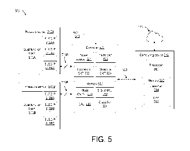
[0049] FIG. 5 is a pressure sensing system according to a
possible implementation of the
present disclosure. The pressure sensing system includes at least one pressure
sensor. For
example, the pressure sensing system 500 can include a first pressure sensor
510A and a
second pressure sensor 510B. The first pressure sensor 510A may include a
first dual-
function foam pad 511A affixed to (e.g., bonded) an electrode matrix having a
first number
11
CA 03236855 2024- 4- 30
WO 2023/077168
PCT/US2022/079086
electrode pairs 512AA, 512AB, 512AC. The second pressure sensor 510A may
include a
second dual-function foam pad 511B affixed to (e.g., bonded) to an electrode
matrix having a
second number of electrode pairs 512BA, 512BB, 512BC. The first number and the
second
number may be the same or different.
[0050] The electrode pairs of the first pressure sensor 510A may
be communicatively
coupled (e g., electrically coupled) over multiple transmission lines 514A or
a common bus
(e.g., wired or wireless) to a controller 520. The electrode pairs of the
second pressure sensor
510B may be communicatively coupled (e.g., electrically coupled) over multiple
transmission
lines 514B or a common bus (e.g., wired or wireless) to the controller 520 The
controller
may be configured by software instructions (i.e., software, firmware, etc.)
recalled from a
memory 530 of the controller 520. The software/firmware may be configured to
interact with
signals from the electrode pairs detected by a detection circuit 524. FIGS. 4A-
4C illustrate
(non-limiting) examples of the detection circuit 524. The software may further
adjust the
operation of the controller 520 and its circuitry in response to the signals.
[0051] The pressure sensors 510A, 510B may be installed as the
padding of an apparatus
For example, the pressure sensors 510A, 510B may be installed in a shoe insole
in areas of
the insole to best sample pressure of portions (e.g., heel, ball) of a foot
standing on the shoe
insole. Other possible apparatus applications may include a pressure mat, a
seat, padding on
robotic arms/fingers/graspers, and a bed/bedding pad. In a possible
implementation, the
controller 520 is also integrated with (e.g., included in) the application. In
some
implementations, the pressure determined at the different pressure sensors
(e.g., 510A, 510B)
can be summed to determine a weight of the object exerting the pressure.
[0052] The controller 520 may receive a plurality of signals from
the electrode pairs of
the pressure sensors 510A, 510B. The controller may also receive signals from
an
accelerometer 513 integrated with (e.g., included in) the application. An
accelerometer
included in the application is considered operationally coupled to the sensors
(e.g., 510A,
510B) and the controller 520. Signals from the accelerometer 513 may indicate
a motion of
the apparatus, which may be used to determine an operating mode of the
controller 520. For
example, the accelerometer 513 may sense the motion of the shoe insole.
[0053] The controller 520 may include a power source 521, such as
a battery, and a
power circuit 522 configured to control the operation of the controller with
respect to an
amount of energy drawn from the power source 521. For example, the power
circuit 522 may
configure the controller 520 into a sleep mode to reduce an amount of power
drawn from the
power source 521. Reducing the amount of power can include reducing the amount
of power
12
CA 03236855 2024- 4- 30
WO 2023/077168
PCT/US2022/079086
applied between pairs of electrodes to zero. The power circuit 522 may be
triggered to
configure the controller into the sleep mode in response to a no sensed
activity from the
pressure sensors 510A, 510B for a period of time (e.g., time-out period). In a
possible
implementation, sensing activity may include comparing signals from the
electrode pairs of
the pressure sensors to an activity threshold. For example, when a detected
signal from an
electrode pair is below a predetermined activity threshold (e.g., is
approximately zero ( 1%)),
then no sensed activity may be concluded. A timer (e.g., software or hardware)
may be
started when the threshold criterion is satisfied, and if no activity is
sensed for a time-out
period, then the power circuit may be configured to reduce the power consumed
from
circuitry in the controller, such as by disabling circuit operation in the
controller to reduce a
power drawn from the power source 521. For example, a reduction of the
consumed power
from a battery can extend an operating life of a controller 520 powered by the
battery.
[0054] As mentioned, the software that configures the controller
for various functions
may be stored in a memory 530 of the controller 520. In other words, the
controller 520 may
be considered as a processor that can be configured by software instructions
(i.e., software
modules, software programs) recalled from the memory 530 of the controller
520. As a
result, the memory 530 of the controller 520 may include a plurality of
software programs for
various functions.
100551 The plurality of software programs may include a mode
controller 531 configured
to control the operation of the controller 520 according to an operating mode
selected from a
plurality of operating modes. In other words, the mode controller 531 may
operate as a state
machine that moves the controller from one state to another based on signals
from the
pressure sensors (e.g., via the detection circuit 524). For example, one
possible operating
mode includes a sleep mode, such as described above.
[0056] The plurality of software programs may further include a
signal analyzer 532.
The signal analyzer 532 may be configured to a signal corresponding to a
piezoelectric effect
or the piezoresistive effect caused by a pressure on the pressure sensor. The
signal analyzer
may be configured to process (e.g., filter, smooth, bias, combine, etc.) the
signal and/or
determine aspects of the signal. For example, the signal analyzer may be
configured to
determine the frequency content of the signal. In a possible implementation,
the signal
analyzer 532 may be configured to determine if the signal has a frequency
above a frequency
threshold. In another possible implementation, the signal analyzer 532 may
receive a
transmit signal transmitted by an excitation circuit 523 of the controller,
receive signal from
an electrode pair in response to the transmit signal, determine (i.e.,
measure) a resistance of
13
CA 03236855 2024- 4- 30
WO 2023/077168
PCT/US2022/079086
the dual function foam based on the transmit signal and the receive signal. In
another
possible implementation, the signal analyzer 532 may compare the measured
resistance to an
expected resistance (i.e., for a non-compressed sensor) to compute a sustained
pressure
corresponding to the piezoresistive effect of the dual-function foam. The
expected resistance
from the non-compressed sensor may be determined from a calibration of the
dual-function
foam in a particular material stack (e.g., a material model for the pressure
sensor). The
outputs of the signal analyzer 532 may be pressure signals that can be sampled
and stored by
location (e.g., corresponding to electrode pair position) and/or by time.
100571 The plurality of software programs may further include a
calibration 533. The
calibration 533 may include values to represent a response of a pressure
sensor to a transient
or sustained pressure. For example, the expected resistance of the dual
function foam may be
stored in a look-up table. The calibration may also include a model (e.g.,
mathematical
equation, neural network, lookup table, database, etc.) in which measurement
(e.g., measured
resistance, measured voltage) is related to a characteristic of the foam
(e.g., strain rate) under
various conditions (e.g., temperature from a temperature sensor (not shown))
The model
may be generated using a calibration process. The calibration process may be
performed at a
time of fabrication (e.g., factory set).
[0058] The plurality of software programs may further include a
classifier 534. The
classifier 534 may be configured to receive the pressure signals. The
classifier 534 may be
configured to determine feedback for an application. For example, a classifier
534 may be
configured to map the determined local strains in areas defined by electrode
pairs and convert
the local strains to a map of pressure on the surface of the dual-function
foam. Based on this
map the classifier 534 may be able to determine a feedback signal which can be
used to alert
a user (a caretaker or person using the apparatus), change a position of a
user to change the
pressure map, or to otherwise improve a condition for a user.
100591 In an alternate implementation, one or more of the
plurality of software programs
(e.g., mode controller 531, signal analyzer 532, calibration 533, or
classifier 534) that
configure the controller 520 to perform a function may be stored in a memory
550 of a
computing device 540 and communicated from the computing device 540 to the
controller
520 over a wireless communication link 525. In other words, the controller 520
and the
computing device 540 may form a split-computing acritude in which processing
for the
pressure sensing system is distributed between the devices. In a possible
implementation, the
computing device 540 is a mobile computing device, such as a laptop, mobile
phone, tablet,
14
CA 03236855 2024- 4- 30
WO 2023/077168
PCT/US2022/079086
etc. The computing device 540 can be communicatively coupled to the controller
520 over a
wireless communication link 525 (e.g., WiFi, Bluetooth, NFC, 5G, etc.).
[0060] The computing device 540 may include a processor 541 that
can be configured by
software instructions (i.e., software modules, software programs) recalled
from the memory
530 to cause the computing device 540 to perform a function (or functions). As
a result, the
memory 530 of the computing device 540 may include a plurality of software
programs for
various functions performed by the computing device 540.
[0061] The plurality of software programs may further include the
classifier 534 as
described above and may further include an application 552. The application
552 may be for
presenting or understanding the classification of the pressures measured by
the pressure
sensing system 500. Accordingly, a user may interact with the application 552.
Some
possible applications will be described below.
[0062] FIG. 6 is a state diagram of operating modes of a
controller for a pressure sensing
system, such as system 500 shown in FIG. 5. The controller may be configured
to receive a
signal from an electrode pair that corresponds to the piezoelectric effect or
the piezoresistive
effect of the dual-function foam. Based on this signal, the controller may be
configured to
select an operating mode from a plurality of operating modes to measure a
transient pressure
or a sustained pressure on a pressure sensor. In other words, the controller
may be configured
to move between operating modes according to conditions at the pressure
sensors.
[0063] As shown in FIG. 6, the plurality of operating modes may
include a dynamic
mode 610. In the dynamic mode of operation, the controller is configured to
measure a
piezoelectric effect of the pressure sensor. For example, a transient pressure
(e.g., impact) on
the dual-function foam may create a voltage as a result of the piezoelectric
effect of the foam.
The controller may passively sense this voltage. In other words, the
controller does not need
to transmit a transmit signal to the electrode pair in order to sense the
transient pressure and
the piezoelectric effect occurs without power source The signal from the
electrode pairs in
the dynamic mode may have a spectrum (i.e., frequency content) that includes
one or more
frequencies above a frequency threshold. Accordingly, the dynamic mode 610 may
be
entered when the signal from the electrode pair has a frequency detected above
the frequency
threshold and the static mode 620 may be entered when the signal from the
electrode pair has
no frequency detected above the frequency threshold. In implementations that
reduce power
when not in the static mode 620, moving to the static mode 620 may restore
power levels,
i.e., wake the controller.
CA 03236855 2024- 4- 30
WO 2023/077168
PCT/US2022/079086
[0064] In some implementations, an accelerometer may be used to
enter the dynamic
mode 620 and stay in the dynamic mode. In such implementations, movement
sensed by an
accelerometer may indicate the system observes transient pressure events.
Accordingly, the
dynamic mode 610 may be entered when a signal from an accelerometer indicates
movement
(i e , a movement signal from the accelerometer). In some implementations,
when the
accelerometer indicates movement, the controller may be configured to reduce
power
consumption from a power source while in the dynamic mode 610. In other words,
because
power is not needed to sense transient strain events, the controller may be
configured to
conserve power, e.g., by reducing an amount of power applied to electrode
pairs to zero while
the controller performs passive sensing.
[0065] As shown in FIG 6, the plurality of operating modes may
include a static mode
620. In the static mode of operation, the controller is configured to measure
a piezoresistive
effect of the pressure sensor. For example, a sustained pressure on the dual-
function foam
may create a change in resistance as a result of the piezoresistive effect of
the foam. This
change in resistance may be actively sensed by the controller. In other words,
the controller
is configured to transmit a transmit signal to the electrode pair in order to
sense the sustained
pressure. The received signal from the electrode pairs in response to the
transmit signal may
have a spectrum (i.e., frequency content) that includes no frequencies above a
frequency
threshold. Accordingly, the controller may remain in the static mode 620 while
the received
signal from the electrode pair has no frequency above the frequency threshold
or move to
dynamic mode 610 when the received signal from the electrode pair has a
frequency above
the frequency threshold. Alternatively, no movement sensed by an accelerometer
may
indicate a sustained pressure. Accordingly, the controller may remain in
static mode 620
when a signal from an accelerometer indicates no movement or move to dynamic
mode 610
when the signal from the accelerometer indicates movement.
100661 As shown in FIG. 6, the plurality of operating modes may
include a sleep mode
630. In the sleep mode of operation, the controller is configured to lower its
power because
the dual-function foam is in a resting state (i.e., no sustained pressure and
no transient
pressure). The sleep mode 630 may be entered from the dynamic mode 610. For
example,
when no voltage (e.g., V = 0) is measured for a time-out period (e.g., dynamic
time-out
period), then the controller may enter sleep mode 630. The time-out period in
the dynamic
mode 610 (e.g., the dynamic time-out period) can be measured in seconds (e.g.,
a few
seconds long). The controller may consume less power in the sleep mode 630
than in the
dynamic mode 610.
16
CA 03236855 2024- 4- 30
WO 2023/077168
PCT/US2022/079086
[0067] The sleep mode 630 may also be entered from the static
mode 620. For example,
when no resistance change (DR) is measured for a time-out period (e.g., static
time-out
period), then the controller may enter sleep mode 630. In other words, when
the dual-
function foam has a resting resistance (R = R REST) for the time-out period,
then the
controller may enter sleep mode 630. In some implementations, the time-out
period in the
static mode 620 can be measured in minutes (e.g., 1 minute, 10 minutes). In
some
implementations, the static time-out period is the same as the dynamic time-
out period. The
controller may consume less power in the sleep mode 630 than in the static
mode 620.
100681 The controller may exit the sleep mode 630 to the dynamic
mode 610 or
(optionally) the static mode 620 based on the response of the pressure sensor.
In one possible
implementation, exiting sleep mode 630 (i.e., waking the controller) may
include configuring
the controller to monitor a voltage of an electrode pair, and when the voltage
exceeds a
threshold (e.g., V> 0) then waking the controller by entering the dynamic mode
610. In the
dynamic mode 610, the frequency content of the voltage is analyzed to
determine whether the
remain in the dynamic mode 610 or move to the static mode 620. When a pressure
sensor
includes a matrix of electrode pairs, then the controller may be configured to
monitor one or
more (e.g., all) of the electrode pairs in the matrix of electrode pairs while
in the sleep mode
630 and to wake from the sleep mode when a voltage satisfying a criterion
(e.g., exceeding a
threshold) is detected at any of the monitored electrode pairs.
[0069] FIG. 7 is a flow chart of a method for sensing pressure
according to a possible
implementation of the present disclosure. The method 700 includes receiving
710 (e.g., at a
controller) from an electrode pair of a pressure sensor including a dual-
function foam (i.e.,
dual-function foam sensor). The method 700 further includes determining 720 a
frequency
content of the signal and comparing 725 the frequency content to a frequency
threshold. For
example, a time-based signal may be transformed (e.g., via a discrete Fourier
transform) to a
frequency-based signal to determine frequency content. The frequency content
may include
frequencies corresponding to the signal that are above a frequency threshold.
When at least
one of the frequencies above a frequency threshold have a magnitude above a
predetermined
amount 730, then the method 700 includes measuring 740 a transient pressure on
the dual-
function foam sensor. When none of the frequencies above the frequency
threshold have a
magnitude above a predetermined amount 730, then the method 700 includes
measuring 750
a sustained pressure on the dual function foam sensor.
[0070] Measuring 740 a transient pressure on the dual-function
foam sensor may include
receiving 741 a voltage of the dual-function foam that corresponds to a
piezoelectric effect of
17
CA 03236855 2024- 4- 30
WO 2023/077168
PCT/US2022/079086
the dual-function foam in response to the transient pressure and measuring 742
the transient
pressure based on the voltage.
[0071] Measuring 750 a sustained pressure on the dual-function
foam sensor may include
transmitting 751 a transmit signal (e.g., PWM signal) to an electrode pair of
the pressure
sensor and receiving 752 a receive signal from the electrode pair in response
to the transmit
signal. Measuring 750 the sustained pressure may further include deletinining
753 the
resistance (i.e., measured resistance) of the dual-function foam based on the
transmit signal
and the received signal. Measuring 750 the sustained pressure may further
include
computing 754 a difference between the resistance and an expected resistance.
The
difference corresponds to a piezoresistive effect of the dual-function foam in
response to the
sustained pressure and measuring 755 the sustained pressure based on the
difference. In a
possible implementation, the difference is a root mean square error between
the resistance
and the expected resistance over a sample period.
100721 Returning to FIG. 5, the pressure sensing system 500 may
be used to sense
pressure in implementations in which padding is used. The computing device 540
may
receive the pressures from a controller 520. Alternatively, or additionally,
the computing
device 540 may receive profiles (e.g., pressure maps, pressure trends,
recognized pressures,
etc.) from the controller 520. An application 552 (i.e., APP) running on a
processor 541 of
the computing device 540 may manipulate information (e.g., pressures,
profiles, etc.)
received from the controller 520 in a meaningful way for a user in the context
of the
implementation. In a first example, the application 552 may configure the
processor 541 of
the computing device to store the information received from the controller 520
to a memory
550 on the computing device or to a device coupled to a network 560 in
communication with
the computing device. In another example, the application 552 may configure
the processor
541 to generate an alert (e.g., sound, light, graphic, etc.) on the computing
device 540 and/or
on a device coupled to a network 560 in response to the information received
from the
controller 520. for a user based on the information received from the
controller 520. In
another example, the application 552 may configured the processor to display
the information
on a graphical user interface (GUI) of the computing device 540 based on the
information
received from the controller 520. The GUI may provide a means for a user to
interact with
the information received from the controller 520.
[0073] Based on the discussion thus far, various implementations
of the pressure sensing
system may be envisioned. In what follows, several possible implementations
are described.
It is recognized that variations, additions, and/or substitutions to the
implementations
18
CA 03236855 2024- 4- 30
WO 2023/077168
PCT/US2022/079086
described are within the scope of the present disclosure when they carry out
the general ideas
conveyed by the implementations described below.
[0074] A first possible implementation is bedding. In the bedding
implementation
pressure sensors are integrated with a bedding surface. For example, a
pressure sensor (or
pressure sensors) could be integrated in a mattress, a mattress top, or a
mattress sleeve to
sense a pressure exerted by a user lying on the mattress. The dual-function
foam and the
electrode matrix of a pressure sensor (e.g., see FIG. 2) can measure and
locate (i.e., map)
pressure points on the user. Calibration of the pressure sensor can be used to
facilitate
consistent and accurate measurements. In a care-giving location (e.g.,
hospital), bedding with
a pressure sensor (i.e., smart bedding) can be used to monitor pressure
locations/magnitudes
(i.e., pressure maps) experienced by bed-bound patients. The pressure sensing
system (e.g.,
see FIGS. 4A-4C) may include an application 552 that can record pressure maps
over time to
provide live feedback of pressure locations and magnitudes. This information
can be used to
determine when a pressure surpasses a critical level (i.e., magnitude
threshold) or duration
(i e , time threshold), which can provide an alert to allow the caretakers to
adjust the patients
to reduce the probability of pressure sore development or other bed-acquired
conditions.
When this information is repeatedly measured and saved, pressure values of the
smart
bedding can be tracked over a period of time. This information can also be
used as feedback
to adjust the bedding to provide comfort to a user by removing high pressure
points. This
feedback may be transmitted to a bed that is communicatively coupled to the
pressure sensing
system (e.g., via a network 560) so that the adjustment may occur
automatically in a bed
configured for automatic adjustment (i.e., mechanical adjustment, pneumatic
adjustment).
100751 FIG. 8 is a flow chart of a method for sensing pressure in
a bedding
implementation of the present disclosure. The method 800 includes receiving
810 signals
from an electrode matrix of a pressure sensor disposed on a surface of bedding
(i.e., surface
supporting a user). The method 800 further includes determining 820 pressures
based on the
received signals and generating 830 a pressure map of the pressures. The
method 800 may
include tracking 825 the pressure maps over time. The method 800 then includes
analyzing
840 the pressure map (or pressure maps over time) to generate feedback (e.g.,
alert, bed
control signal, etc.). The method 800 then includes adjusting 850 the user or
the bedding
based on the feedback.
100761 A second possible implementation is seating. In the
seating implementation,
pressure sensors are integrated with a seat surface or seat surfaces (e.g.,
back surface, leg
surface). The seat may include an automatic adjustment mechanism that can
receive
19
CA 03236855 2024- 4- 30
WO 2023/077168
PCT/US2022/079086
feedback from the pressure sensing system. Accordingly, the seat surface (or
surfaces) can
respond (e.g., in real time) to pressure and/or force changes by the user.
Specifically, this
sensor system can be used in car seats which may be configured to generate
feedback from
the pressure information to adjust the seat to change pressure. The change in
pressure may
result in a more comfortable and/or ergonomic position for the user. This seat
adjustment
may use any system to adj ust the lumbar support, stiffness of any part of the
seat, or shape of
any part of the seat. The pressure sensing system may include a plurality of
pads (i.e.,
pressure sensors), depending on a size of the seat and the size of the
electrode pairs in the
electrode matrix. The seats with pressure sensors (i.e., smart seats) may be
used in a variety
of environments, including (but not limited to) automotive seats, wheelchairs,
office chairs,
and home chairs. In all these uses, the dual-function foam could be integrated
as part of the
chair or be placed on top of the seat to provide force, pressure, and location
information (e.g.,
pressure maps). The pressure information provided by the pressure sensors of
the seats can be
used to adjust the seat automatically (or manually). The adjustment may
provide a better fit
or improve the comfort of a user. In the case of the wheelchair, the pressure
information can
also be used to sense the motion of the user and provide feedback to adjust
the wheelchair or
user for better (e.g., more natural) movement. In some implementations, the
pressure map
may be associated with a particular user and adjust the seat to match a
particular
configuration pre-set the user including seat position, settings within the
car (i.e., mirror
placement, pedal location, temperature controls, etc.)
[0077] FIG. 9 is a flow chart of a method for sensing pressure in
a seating
implementation of the present disclosure. The method 900 includes receiving
910 signals
from an electrode matrix of a pressure sensor (or pressure sensors) disposed
on a surface (or
surfaces) of a seat. The method 900 further includes determining 920 pressures
based on the
received signals and generating 930 a pressure map of the pressures. The
method 900 may
include tracking 925 the pressure maps over time. The method 900 then includes
analyzing
940 the pressure map (or pressure maps over time) to generate feedback (e.g.,
alert, bed
control signal, etc.). The method 900 then includes adjusting 950 (e.g.,
automatically
adjusting) the user or the seat based on the feedback.
[0078] A third possible implementation is a pressure mat. In the
pressure mat
implementation, one or more pressure sensors may be arranged to cover a
surface of the
pressure map. The pressure map may be placed on the floor for a user to stand
on. The
pressure mat can be configured to measure the location and magnitude of the
forces (i.e.,
pressure map) exerted by the user on the pressure mat. The pressure maps may
provide
CA 03236855 2024- 4- 30
WO 2023/077168
PCT/US2022/079086
feedback that can aid in sporting, physical therapy, and human performance
applications to
visualize ground reaction forces and center of pressure to improve form and
performance.
An application miming on a computing device (e.g., phone, computer, smart TV,
etc.) of the
pressure sensing system may be configured to provide immediate feedback of the
distribution
of weight during a swing, pitch, exercise, or any dynamic or static motion.
The application
may configure a processor to display the pressure information to the user in
real time, as well
as record the changes in pressure over time to a memory for later display.
Further the
application, may be configured to recognize pressures as a movement and to
generate
feedback (e.g., instructions, tips, etc.) to help a user improve the movement
(e.g., golf swing)
based on a comparison of the recognized movement and a stored movement (e.g.,
ideal
movement). The feedback could be for exercises to improve form, maximize
rehab, or
improve performance. The pressure mat may also be used in strength training,
sports
including (but not limited to) golf, baseball, and basketball, rehabilitation,
or security, safety
(e.g., door control), and/or movement monitoring. For example, during lower-
limb
rehabilitation or with other semi-ambulatory patients, a pressure mat may be
set up around
their living space to alert others of falls or other irregularities in their
mobility.
[0079] FIG. 10 is a flow chart of a method for sensing pressure
in a pressure mat
implementation of the present disclosure. The method 1000 includes receiving
1010 signals
from an electrode matrix of a pressure sensor (or pressure sensors) disposed
on a surface (or
surfaces) of a pressure map. The pressure mat may be placed on a floor or
ground for a user
to step onto (or stand on). The method 1000 further includes determining 1020
pressures
based on the received signals and generating 1030 a pressure map of the
pressures. The
method 1000 may include tracking 1025 the pressure maps over time. The method
1000 then
includes analyzing 1040 the pressure map (or pressure maps over time) to
recognize a
movement. For example, a classifier may be configured to output a recognized
movement
based on a plurality of pressure inputs. The method 1000 may optionally
include comparing
1050 the recognized movement to a stored movement (e.g., database of
movements). The
method 1000 may then include providing 1060 feedback according to the
recognized
movement.
[0080] A fourth possible implementation is a shoe insole. In the
shoe insole
implementation, a pressure sensor (or pressure sensors) may be laid out in the
shape of a shoe
insole. Multiple electrode matrices may be placed in areas of the foot that
give measurements
corresponding to a distribution of pressure while a user is standing, walking,
running, or
sitting. An application of the pressure sensor system can be configured to
provide feedback to
21
CA 03236855 2024- 4- 30
WO 2023/077168
PCT/US2022/079086
help a user determine the comfort of a particular pair of shoes or the effect
that an injury,
developmental issue, or wearable has on their static or dynamic stance.
efficacy
[0081] FIG. 11 is a flow chart of a method for sensing pressure
in a shoe insole
implementation of the present disclosure. The method 1100 includes receiving
1110 signals
from pressure sensors integrated in different areas of a shoe insole. The
method 1100 further
includes determining 1120 pressures based on the signals from the pressure
sensors. The
method 1100 further includes monitoring 1130 the pressures while a user
stands, sits, and/or
moves (e.g., walks, runs, jumps, etc.) in the shoes. The method further
includes providing
1140 feedback based on the monitored pressures to help the user determine fit
(e.g., comfort)
and/or efficacy (e.g., correction) of the shoe.
[0082] Some other implementations of the pressure sensor system
can include smart
shipping, measuring pressure on prosthetics, measuring gasket seals, grip
strength testing,
robotic feedback, and storage of sensitive materials. In smart shipping and
storage, the foam
aspect of the pressure sensor can allow for safe and protective contact with a
packaged object
while measuring vibrations and changes in applied forces during shipping. For
grip strength
testing, the foam of the pressure sensor can provide a comfortable padding
while providing
magnitude and location of pressure to test for early onset of diseases or
measure progress
over time. For measuring gasket seals, the compliance of the foam can help
form a seal while
providing specific force and position data to ensure a uniform and complete
seal. For robotic
feedback, a stiff and powerful robot may have the sensor incorporated into any
moving part
that could include a negative feedback loop. As an unexpected strain or
pressure is detected
on the moving system, the robot would pause operation or change course. It
could also be
used to guide the robot to the correct location or to the correct force when
accomplishing a
task.
[0083] In some aspects, the techniques described herein relate to
a pressure sensing
system including: a pressure sensor including: a dual-function foam configured
to: generate a
piezoelectric effect in response to a transient pressure; and generate a
piezoresistive effect in
response to a sustained pressure; and an electrode pair disposed on a surface
of the dual-
function foam; and a controller electrically coupled to the electrode pair,
the controller
configured to: receive a signal from the electrode pair, the signal
corresponding to the
piezoelectric effect or the piezoresistive effect; and select an operating
mode from a plurality
of operating modes based on the signal in order to measure the transient
pressure or the
sustained pressure, the plurality of operating modes including a static mode
in which the
controller is configured to measure the piezoresistive effect of the sustained
pressure and a
22
CA 03236855 2024- 4- 30
WO 2023/077168
PCT/US2022/079086
dynamic mode in which the controller is configured to measure the
piezoelectric effect of the
transient pressure.
[0084] These and other aspects can include one or more of the
following, alone or in
combination. For example, the controller can be configured to: select the
static mode as the
operating mode when the signal has no frequency above a frequency threshold,
the static
mode configured to measure tile sustained pressure according to a resistance
of the dual-
function foam. In such implementations, to measure the sustained pressure, the
controller can
be configured to: transmit a transmit signal to the electrode pair; receive a
receive signal from
the electrode pair in response to the transmit signal; determine the
resistance of the dual-
function foam based on the transmit signal and the receive signal; compute a
difference
between the resistance and an expected resistance, the difference
corresponding to the
piezoresistive effect of the dual-function foam in response to the sustained
pressure; and
measure the sustained pressure based on the difference. The resistance can be
calculated
based on a root mean square signal. The expected resistance can be obtained
from a
calibration of the pressure sensor and stored in a memory of the controller In
some
implementations, the plurality of operating modes include a sleep mode and the
controller is
further configured to: select the sleep mode as the operating mode when the
sustained
pressure is approximately zero for a time-out period, wherein in the sleep
mode the controller
consumes less power than in the static mode.
[0085] As another example, the controller can be configured to:
select the dynamic mode
as the operating mode when the signal has a frequency above a frequency
threshold, the
dynamic mode configured to measure the transient pressure according to a
voltage of the
dual-function foam. In some such implementations, to measure the transient
pressure, the
controller can be configured to: receive the voltage from the electrode pair,
the voltage
corresponding to the piezoelectric effect of the dual-function foam in
response to the transient
pressure; and measure the transient pressure based on the voltage. In some
implementations,
the controller can be further configured to: select a sleep mode as the
operating mode when
the transient pressure is approximately zero for a time-out period, wherein in
the sleep mode
the controller consumes less power than in the dynamic mode.
[0086] As another example, the controller can be configured to:
select the operating mode
based on a movement signal from an accelerometer operationally coupled to the
pressure
sensor and in communication with the controller. As another example, the
electrode pair is a
first electrode pair of a plurality of electrode pairs disposed on the surface
of the dual-
function foam, the controller further configured to: receive a plurality of
signals from the
23
CA 03236855 2024- 4- 30
WO 2023/077168
PCT/US2022/079086
plurality of electrode pairs; and map the transient pressure or the sustained
pressure based on
the plurality of signals
[0087] In some aspects, the techniques described herein relate to
a method for sensing
pressure, including: receiving a signal from an electrode pair disposed on a
dual-function
foam, determining a frequency content of the signal; comparing the frequency
content of the
signal to a frequency threshold, measuring a transient pressure on the dual-
function foam
according to a voltage of the dual-function foam when the signal has frequency
content above
the frequency threshold; and measuring a sustained pressure on the dual-
function foam
according to a resistance of the dual-function foam when the signal has
frequency content
below the frequency threshold.
[0088] These and other aspects can include one or more of the
following, alone or in
combination For example, measuring the transient pressure on the dual-function
foam can
include: receiving the voltage from the electrode pair, the voltage
corresponding to a
piezoelectric effect of the dual-function foam in response to the transient
pressure; and
measuring the transient pressure based on the voltage. As another example,
measuring the
sustained pressure can use a material model configured to compensate for drift
in the
resistance.
[0089] As another example, measuring the sustained pressure on
the dual-function foam
can include. transmitting a transmit signal to the electrode pair; receiving a
receive signal
from the electrode pair in response to the transmit signal; determining the
resistance of the
dual-function foam based on the transmit signal and the receive signal;
computing a
difference between the resistance and an expected resistance, the difference
corresponding to
piezoresistive effect of the dual-function foam in response to the sustained
pressure; and
measuring the sustained pressure based on the difference. In some
implementations, the
transmit signal is a pulse width modulation (PWM) signal. In some
implementations,
determining the resistance of the dual-function foam based on the transmit
signal and the
receive signal can include computing a root mean square (RMS) of the receive
signal.
[0090] In some aspects, the techniques described herein relate to
a pressure sensing
system including: a pressure sensor including: a dual-function foam configured
to change
electrical properties according to on a strain applied to the dual-function
foam; a matrix of
electrode pairs disposed on a surface of the dual-function foam, the electrode
pairs arranged
contiguously in a grid pattern so that the electrode pairs substantially cover
the surface of the
dual-function foam; and a controller electrically coupled to the electrode
pairs, the controller
configured to: receive signals from the electrode pairs, the signals from the
electrode pairs
24
CA 03236855 2024- 4- 30
WO 2023/077168
PCT/US2022/079086
corresponding to local strains in areas defined by the electrode pairs; and
convert the local
strains to a map of pressures on the surface of the dual-function foam.
[0091] These and other aspects can include one or more of the
following, alone or in
combination. For example, each electrode pair can include a first electrode
having a first
plurality of fingers and a second electrode coplanar with the first electrode
and having a
second plurality of fingers, wherein the first plurality of fingers and the
second plurality of
fingers are interdigitated. As another example, the dual-function foam can
include a
polymeric matrix, one or more conductive fillers, and voids. As another
example, the signals
can include one or more of: a voltage corresponding to a piezoelectric
response to a transient
pressure on the dual-function foam; and a voltage corresponding to a
piezoresistive response
to a sustained pressure on the dual-function foam
[0092] As another example, a model of the dual-function foam can
be used to convert the
local strains to the map of pressures on the surface of the dual-function
foam, the model
generated using a calibration process. As another example, the controller can
be configured
to: enter a sleep mode to reduce a power consumed by the controller when the
signals from
the electrode pairs indicate no local strains in the areas defined by the
electrode pairs;
monitoring the matrix of electrode pairs for a voltage at any electrode pair
in the matrix of
electrode pairs that exceeds a threshold; and wake from the sleep mode when
the voltage is
detected.
[0093] While certain features of the described implementations
have been illustrated as
described herein, many modifications, substitutions, changes and equivalents
will now occur
to those skilled in the art. It is, therefore, to be understood that the
appended claims are
intended to cover all such modifications and changes as fall within the scope
of the
implementations. It should be understood that they have been presented by way
of example
only, not limitation, and various changes in form and details may be made. Any
portion of
the apparatus and/or methods described herein may be combined in any
combination, except
mutually exclusive combinations. The implementations described herein can
include various
combinations and/or sub-combinations of the functions, components and/or
features of the
different implementations described.
[0094] It will be understood that, in the foregoing description,
when an element is
referred to as being on, connected to, electrically connected to, coupled to,
or electrically
coupled to another element, it may be directly on, connected or coupled to the
other element,
or one or more intervening elements may be present. In contrast, when an
element is referred
to as being directly on, directly connected to or directly coupled to another
element, there are
CA 03236855 2024- 4- 30
WO 2023/077168
PCT/US2022/079086
no intervening elements present. Although the terms directly on, directly
connected to, or
directly coupled to may not be used throughout the detailed description,
elements that are
shown as being directly on, directly connected or directly coupled can be
referred to as such.
The claims of the application, if any, may be amended to recite example
relationships
described in the specification or shown in the figures.
[0095] As used in this specification, a singular form may, unless
definitely indicating a
particular case in terms of the context, include a plural form. Spatially
relative terms (e.g.,
over, above, upper, under, beneath, below, lower, and so forth) are intended
to encompass
different orientations of the device in use or operation in addition to the
orientation depicted
in the figures. In some implementations, the relative terms above and below
can,
respectively, include vertically above and vertically below. In some
implementations, the
term adjacent can include laterally adjacent to or horizontally adjacent to.
26
CA 03236855 2024- 4- 30