Note: Descriptions are shown in the official language in which they were submitted.
WO 2023/085938
PCT/NL2022/050648
HIGH-PRESSURE ELECTROLYSIS DEVICE
Field of the Invention
The present invention relates generally to a device for generating hydrogen
and
oxygen comprising a high-pressure electrolyzer, wherein the electrolyzer
comprises a
plurality of high-pressure electrolysis units which are arranged in series.
The invention also
relates to a method to produce high-pressure hydrogen at pressures up to
100.000 KPa or
higher and by-product oxygen without the need for a separate compressor to
pressurize the
hydrogen gas produced.
Backaround of the Invention
Electrolytic production of hydrogen is well known. See, for example, WO
2004/076721 and the U.S. patent publications cited therein.
As described in the introduction of WO 2004/076721, known electrolytic
equipment, also referred to in the art as "electrolyzers", using liquid
electrolyte to generate
hydrogen, operates in the following way. Two electrodes are placed in a bath
of liquid
electrolyte, such as an aqueous solution of potassium hydroxide (KOH). A broad
range of
potassium hydroxide concentration may be used, but usually a concentration of
about 25 to
30% by weight KOH solution is used. The electrodes are separated from each
other by a
separation membrane that selectively allows passage of liquid but no gas. When
a voltage
is impressed across the electrodes, commonly about 2-3 Volts, current flows
through the
electrolyte between the electrodes. Hydrogen gas is produced at the cathode
and oxygen
gas is produced at the anode. The separation membrane keeps the hydrogen and
oxygen
gases separated as the generated gas bubbles rise through the liquid
electrolyte. There is
a disengagement space above the liquid electrolyte comprised of two separate
chambers or
two sections isolated from each other by being separated by a gas-tight
barrier into two
separate sections, one chamber or section to receive the hydrogen gas and the
other to
receive the oxygen gas. The two gases are separately removed from the
respective sections
of the disengagement space for storage or venting.
The currently available electrolyzers are mainly low pressure electrolyzers
with
a stacked design, with sets of prefabricated parts stacked to assemble the
electrolyzer. Due
to the nature of stacked designs the pressure is limited to about 30 bar.
High-pressure electrolyzers are becoming of major interest since they have the
advantage over low-pressure electrolyzers in that they are suitable to be used
in high
pressure applications, transport and storage without the need for a downstream
compressor
CA 03237384 2024- 5-6
WO 2023/085938
PCT/NL2022/050648
2
stage. A variety of designs of high-pressure electrolyzers has been described
in the art which
are often based on polymer electrolyte membrane ("PEM") technology. See, for
example,
WO 2011/012507 Al. However, an important drawback of the PEM technology is
that it
requires an expensive catalyst of rare metallic material and the catalyst
layers in the
electrolysis cells degrade faster at varying load requirements than in the
alkali electrolysis.
WO 2021/029768 Al discloses a high-pressure alkaline electrolysis device
comprising an assembly of tubes and pipes of electrically conductive metal
which constitute
either the anode or the cathode, with a channel arrangement of interconnected
vertical and
horizontal pipes and tubes which are closed at their outer ends except the
pipes for water inlet
and hydrogen and oxygen outlet connections, wherein the internal face of the
channel
arrangement is coated with an electrically insulating coating, and wherein the
counter
electrodes which constitute the cathodes or anodes, respectively, are
positioned in the vertical
pipes being enveloped by a cylindrical membrane and supported and connected by
electrode
support bars which are installed in horizontal pipes in the upper part of the
housing. The high-
pressure electrolysis device further comprises one or more pressure-tight
isolated electrical
conductors to conduct electrical power supply from the outside to the inside
of the
electrolysis device.
WO 2004/076721 A2 which corresponds to EP 1597414 B1 discloses an
electrolyzer cell for the electrolysis of water which comprises a cathode of
generally tubular
configuration within which is disposed an anode separated from the cathode by
a separation
membrane of generally tubular configuration which divides the electrolyte
chamber into an
anode sub-chamber and a cathode sub-chamber. An electrolyzer apparatus
includes an
array of individual cells across each of which an electric potential is
imposed by a DC
generator via electric leads. Hydrogen gas generated within cells from
electrolyte is removed
via hydrogen gas take-off lines and hydrogen manifold line. By-product oxygen
is removed
from cells by oxygen gas take-off lines and oxygen manifold line.
NL 2023212 discloses a high-pressure electrolysis device comprising a massive
block of electrically conductive metal, which constitutes either the anode or
the cathode, with
an arrangement of interconnected vertical and horizontal cylindrical channels,
which are
closed at the outer ends except the channels for water inlet and hydrogen and
oxygen outlet
connections, wherein the internal face of the channel arrangement is partially
coated with
an electrically insulating coating, and wherein the counter electrodes which
constitute the
cathodes or anodes, respectively, are positioned in the vertical channels
enveloped by a
cylindrical membrane and supported and connected by electrode support bars
which are
installed in horizontal channels in the upper part of the housing.
CA 03237384 2024- 5-6
WO 2023/085938
PCT/NL2022/050648
3
EP 3 498 886 Al discloses an electrolysis system to conduct oxidation and
reduction reactions comprising two or more groups of electrolytic cells which
are connected
in parallel, the electrolytic cells being formed by at least a pair of
electrodes and an
electrolyte between the electrodes, wherein the assembly of said electrolytic
cells defines
an electrolyzer; an energy source that supplies an electrical signal to the
electrolyzer;
wherein the electrical signal received by the electrolytic cells that form the
electrolyzer
correspond to a direct current pulse which is configured for each
electrolyzer's cells to
operate in a charge transient regime of each cell during the direct current
pulse and in a discharge
transient regime of each cell during the time between the direct current
pulses, wherein said charge
and discharge transient regimes are defined by the construction of each
electrolytic cell in
the form of a cylindrical plates capacitor.
US 3,984,303 discloses an electrolytic cell for the production of halogen gas
and
alkali metal hydroxide, having a hollow tubular cathode member with a hollow
tubular anode
member disposed concentrically within the cathode, each electrode member
having liquid
permeable walls to allow the circulation of electrolyte. The anode is covered
on its outer
surface with an electrically conductive, tubular membrane of a material
selectively
permeable to the passage of ions and impervious to hydrodynamic flow of the
electrolyte,
which is fitted over the outer surface of the anode, thereby separating the
anode and cathode
surfaces. Such cells may also be connected in series to form a larger multi-
cell electrolyzer.
There is still a need for simple, efficient and cost-effective high-pressure
electrolyzers for the production of hydrogen and other industrial processes,
which are
compact, flexible, modular, scalable, and require low maintenance. It is an
object of the
present invention to provide such a high-pressure electrolysis device.
Summary of the Invention
In one aspect of the present invention a high-pressure electrolysis unit for
generating hydrogen and oxygen is provided comprising:
- a body of electrically conductive metal, made up of an assembly of inter-
connected horizontal and vertical tubes, said body constituting an electrode,
anode or cathode,
which is connectable to a source of DC electricity;
- wherein said assembly comprises three horizontal tubes, the first tube,
defined
as the lower horizontal tube constituting the bottom of the body and the two
other tubes, defined
as the first upper horizontal tube and the second upper horizontal tube,
respectively, which are
situated at neighbouring distance from each other in the upper part of the
body;
CA 03237384 2024- 5-6
WO 2023/085938
PCT/NL2022/050648
4
- wherein said assembly comprises at least two vertical tubes, the vertical
tubes
being arranged in a row and having lower and upper outer ends, the lower outer
ends being
connected to said lower horizontal tube and the upper outer ends being sealed;
- wherein the vertical tubes extend from the lower horizontal tube, are then
interconnected with the second upper horizontal tube and the first upper
horizontal tube, and
extend further to beyond the first upper horizontal tube, the upper outer
parts constituting
the top of the body;
- wherein each of said vertical tubes accommodate an elongated central
electrode, which is electrically isolated from the vertical tube and defines a
counter electrode,
cathode or anode, respectively, each central electrode extending from the
lower part of the
respective vertical tube and protruding through the seal to beyond the upper
outer end of
said vertical tube, said central electrodes being connectable to a source of
DC electricity;
- wherein a separation membrane of tubular configuration, extending from the
area between the connection of the vertical tube with the lower horizontal
tube and the lower
outer end of the central electrode up to the area between the second upper and
first upper
horizontal tube, is placed within each vertical tube, concentric between the
cathode and the
anode to divide said cell into an anode sub-chamber and a cathode sub-chamber,
the
separation membrane sealing against the passage therethrough of gases but
permitting
passage of liquid and liquid borne ions;
- wherein gas-tight seals are placed between said separation membrane and
the inner wall of the vertical tube between the two upper horizontal tubes of
the body, which
are also supporting the membrane;
- wherein each central electrode together with the inner wall of the vertical
tube
surrounding said central electrode, the tubular membrane and an electrolyte
provided
between said electrodes defines an electrolytic cell; and
- wherein the body further comprises at least two additional vertical tubes
not
accommodating central electrodes, the first vertical tube connecting the lower
horizontal
tube to the first upper horizontal tube and the second vertical tube
connecting the lower
horizontal tube to the second upper horizontal tube.
In another aspect of the invention a high-pressure electrolyzer is provided
comprising a plurality of high-pressure electrolysis units as defined above,
which are
electrically connected in series.
In still another aspect of the invention a high-pressure electrolyzer is
provided
comprising a plurality of high-pressure electrolysis units as defined above,
further comprising
a cooling and drying unit.
CA 03237384 2024- 5-6
WO 2023/085938 PC
T/NL2022/050648
In a further aspect of the invention a device is provided comprising a high-
pressure electrolyzer comprising a plurality of high-pressure electrolysis
units as defined
above, and one or more pressure containers
These and other aspects of the present invention will be more fully outlined
in
5 the detailed description which follows with reference to a particular
embodiment thereof, i.e.
the production of hydrogen and oxygen by high-pressure electrolysis of water.
However,
those skilled in the art will recognize that the invention may be utilized in
other embodiments.
Conventional known devices such as pressure-sensing and flow-rate sensing
devices, and controls to operate valves and pumps, have been largely omitted
from the
description, as such devices and their use are well known in the art.
Brief Description of the Drawings
Figure 1 is a schematic front side view of an embodiment of a high-pressure
electrolysis unit according to the invention;
Figure 2 is a schematic side view of the electrolysis unit of Figure 1;
Figure 3 is a schematic perspective view of another embodiment of a high-
pressure electrolysis unit according to the invention;
Figure 4 is a detailed view of the upper part of a vertical tube with an
elongated
electrode mounted therein;
Figure 5 is a partial longitudinal view of an electrolysis cell according to
the state
of the art, and a cross-sectional and a perspective view of an embodiment of
an electrolysis
cell which forms part of a high-pressure electrolysis unit according to the
invention;
Figure 6 is a perspective view of an embodiment of a high-pressure
electrolysis
unit according to the invention;
Figure 7 is a schematic side view of an embodiment of four high-pressure
electrolysis units according to the invention in a serial arrangement;
Figure 8 is a perspective view of an embodiment of an electrolyzer with
multiple
(16) high-pressure electrolysis units according to the invention in a serial
arrangement, and
cooling and drying devices for the generated gases connected thereto;
Figure 9 is a schematic view of the electrolyzer of Figure 8;
Figure 10 is a more detailed schematic view of the cooling device of Figure 9;
Figure 11 is a flow chart of an embodiment of the cooling device for the
generated gases in an electrolyzer according to the invention.
The following detailed description should be read with reference to the
drawings
in which like elements in different drawings are numbered identically. The
drawings, which
CA 03237384 2024- 5-6
WO 2023/085938
PCT/NL2022/050648
6
are not necessarily to scale, depict selected embodiments and are not intended
to limit the
scope of the invention.
Detailed Description of the Invention
A high-pressure electrolysis unit according to the invention comprises a body
made up of an assembly of interconnected horizontal and vertical tubes of high-
pressure
and temperature-resistant conductive material, and no stacked design. The
assembly is
used as the containment for the high-pressure electrolysis process. High
operating
pressures are possible and no compression is needed to store and distribute
product gas,
resulting in an increased total efficiency, as no compression of the product
gas is needed
downstream.
The words "tubes" and "pipes" are frequently used interchangeably in the art,
although there are differences between tubes and pipes. Reference may be made
to, e g.,
http://www.wermac.orq/pipesiolpe vs tube,html. As used herein, "tubes" and
"pipes" are
collectively referred to as "tubes", unless stated otherwise. A skilled person
in the art will
have no problem in understanding which materials are needed when applying a
design
according to the invention.
The body of the electrolysis unit constitutes an electrode, anode or cathode,
which
is connectable to a source of DC electricity. In a preferred embodiment, the
assembly of
interconnected horizontal and vertical tubes comprises three horizontal tubes.
One tube,
hereinafter referred to as the lower horizontal tube, constitutes the bottom
of the body. The two
other tubes, hereinafter referred to as the first upper horizontal tube and
the second upper
horizontal tube, respectively, are situated at neighbouring distance from each
other and form
part of the upper part of the body.
The assembly of interconnected horizontal and vertical tubes comprises at
least
two, and preferably a plurality of vertical tubes, e.g. from three to twenty
up to fifty or more
vertical tubes. A preferred number of vertical tubes is in the range of 15-50
tubes per electrolysis
unit. The vertical tubes having lower and upper outer ends are arranged in a
row, the lower
outer ends being connected to the lower horizontal tube. The vertical tubes
extend from the
lower horizontal tube, are interconnected with the second upper horizontal
tube and the first
upper horizontal tube, and extend further to beyond the first upper horizontal
tube. The upper
outer ends of the vertical tubes constitute the top of the body and are
sealed. In a preferred
embodiment, the upper outer ends of the vertical tubes are threaded to
facilitate
maintenance of the unit and assembly of other parts into the vertical tubes.
The vertical
tubes may be closed with readily available pressure fittings which are known
in the art, such
as threaded pressure fittings.
CA 03237384 2024- 5-6
WO 2023/085938 PC
T/NL2022/050648
7
The vertical tubes are adapted to accommodate elongated electrodes which are
isolated from the wall of the tubes. In a preferred embodiment, each of the
vertical tubes
accommodate an elongated central electrode, which extends from the lower part
of said
vertical tube upwards and protrude through the seal of the upper outer end of
the vertical
tube to beyond said upper outer end. The elongated central electrodes
constitute counter
electrodes, cathode or anode, respectively, relative to the electrode of the
body, which are
connectable to a source of DC electricity. In a preferred embodiment, the
elongated central
electrodes are solid, cylindrical bar or rod type electrodes.
The body is filled with a liquid electrolyte, for example a solution of
potassium
hydroxide (KOH) in demineralized water. A broad range of potassium hydroxide
concentrations may be used, but generally a concentration of about 25 to 30
wt.% KOH
solution is used. The electrodes, i.e. the vertical tubes which are part of
the conductive body
and the central electrodes are exposed to, and in contact with, the liquid
electrolyte to
generate gases when in operation.
A separation membrane of tubular configuration is placed within each vertical
tube surrounding the central electrode and thus dividing the concentric space
within the
vertical tube into an anode sub-chamber and a cathode sub-chamber, the
separation
membrane sealing against the passage therethrough of gases but permitting
passage of
liquid and liquid borne ions. The separation membrane is top supported and
extends from
the area between the connection of the vertical tube with the lower horizontal
tube and the
lower outer end of the central electrode up to the area of the vertical tube
between the
second upper horizontal tube and the first upper horizontal tube. In a
preferred embodiment,
the separation membranes are open at the lower side. In another preferred
embodiment,
the membrane is a ZIRFON separation rnernbranel.
Gas-tight seals are placed between the separation membranes and the inner
wall of the vertical tubes between the two upper horizontal tubes. These seals
also support
the membrane. The upper part of the central electrodes is preferably
electrically isolated
around their circumference, crossing the area of the upper two horizontal
tubes, upwards
from the seals to prevent generation of gases in the two upper horizontal
tubes, enabling
high quality of the gas produced.
Each central electrode together with the inner wall of the vertical tube in
which
the central electrode is placed, the separation membrane and the electrolyte
between said
electrodes, define an electrolytic cell. In a preferred embodiment, the inner
wall of the vertical
1 ZIRFON is a registered trade mark
CA 03237384 2024- 5-6
WO 2023/085938
PCT/NL2022/050648
8
tube constitutes the anode (-F) and the central electrode constitutes the
cathode (-) of the
electrolysis cell.
In a particular preferred embodiment, the body further comprises at least two
vertical tubes which do not accommodate central electrodes. The first vertical
tube connects
the lower horizontal tube to the first upper horizontal tube and the second
vertical tube
connects the lower horizontal tube to the second upper horizontal tube. These
additional
tubes are advantageous for the recirculation of the electrolyte and improve
the removal of
the generated gases from the electrolytic cells.
In a preferred embodiment, the high-pressure electrolysis unit according to
the
invention comprises two or more electrolytic cells, e.g. 3, 4, 5, 6, 7, 8, or
a plurality of cells
up to 50, which cells are connected in parallel. In a further preferred
embodiment, the upper
parts of the central electrodes are electrically interconnected outside the
vertical tubes, e.g.
by a conductive profile which in turn is connected to a source of DC
electricity.
When in operation, hydrogen gas is produced at the cathode and oxygen gas is
produced at the anode of each electrolytic cell. The separation membrane keeps
the
hydrogen and oxygen gases separated as the generated gas bubbles rise through
the liquid
electrolyte. There is a disengagement space above the liquid electrolyte
comprised of two
sections which are separated from each other by the gas-tight seal, one
section, i.e. the first
upper horizontal tube, to receive the hydrogen gas and the other section, i.e.
the second
upper horizontal tube, to receive the oxygen gas. The two gases are separately
removed
from the respective tubes for cleaning and drying, storage, transport or
venting.
Each electrolysis unit comprises at least one and preferably two gas take-off
connections in liquid- and gas-flow communication with the respective two
upper horizontal
tubes for removing from the tubes gases generated in the electrolytic cells
and collected in
said tubes. In addition, each unit comprises a connection for a feeding
conduit to supply
liquid electrolyte or demin-water, preferably to the lower horizontal tube of
the unit.
In a further aspect of the invention a high-pressure electrolyzer is provided
comprising a plurality of high-pressure electrolysis units as defined and
described above,
which are connected in series. The combined electrolysis units are preferably
arranged in
electrically isolated adjacent arrays, for example in a way as illustrated in
Fig. 7 and Fig. 8.
As exemplified in Fig. 6, the units are electrically connected such that the
anode (+) of the
body of the first unit is connected a source of DC electricity, the cathode (-
) of the central
electrode of the first unit is connected to the body of the second adjacent
electrolysis unit,
the central electrode of the second electrolysis to the body of the next
adjacent electrolysis
unit, and so on, and the last central electrode (-) is connected to the source
of DC electricity.
The differential voltage over the serially connected units is equal to the
number of units
CA 03237384 2024- 5-6
WO 2023/085938
PCT/NL2022/050648
9
multiplied by the voltage drop over a single unit, which is in the range of 2-
3 Vdc. The current
is equal to the number of parallel cells multiplied by the current through a
single cell, which
is dependent on the detailed design of the cell and the voltage applied over
the cell.
The high-pressure electrolyzer according to the invention comprises at least
two
electrolysis units, but preferably a plurality thereof, e.g. at least 10
units, more preferably at
least 50-150 units. In a preferred embodiment, the electrolysis units are
further bound by
common feeding conduits of liquid electrolyte and demin-water, as well as gas
take-off
conduits of the hydrogen and oxygen gases.
The wall thickness of the body of the high-pressure units according to the
invention is dictated by the desired generation pressure, by material
properties such as yield
strength and electrical conductivity of the metal from which the body is made.
Generally, the
wall thickness may vary from about 0.65 to 1.60 cm. Typically, the length of
the vertical pipes
of the high-pressure units is in the range of 500 to 2000 mm and may be
further developed
up to 4000 mm. Typically, the diameter of the central electrode is about 30 mm
and may be
further developed up to 100 mm. These values are merely indicative and not to
be construed
as limiting the invention in any respect.
In a further aspect of the invention one or more cooling and drying units are
provided which form part of the high-pressure electrolysis device according to
the present
invention. The cooling and drying units are connected with the take-off
conduits of the
produced hydrogen and oxygen gases.
In a preferred embodiment, the produced hydrogen and oxygen gases are
conveyed to a cooling and drying device to be cooled down by a cooling medium,
e.g. cooling
water. After cooling, the oxygen gas is reduced to atmospheric pressure which
results in
another temperature reduction due to the thermodynamic behavior of oxygen. The
oxygen
at ambient conditions is then used to further cool down the hydrogen gas which
still is under
high pressure. The gas cooling unit is designed such that condensed water runs
back into
the electrolysis units. Condensation of water vapor in the downstream systems
is avoided.
Thus, by cooling the hydrogen gas below ambient temperature it will be dried
to a saturation
temperature below atmospheric conditions, thereby preventing water
condensation in
downstream systems.
In another aspect of the invention, one or more pressure containers are
provided
which form part of the electrolysis device according to the present invention.
The pressure
containers are preferably releasably connected to the cooling and drying units
for storage of
the dried and purified gases.
The electrolyzer according to the present invention has several advantages as
compared to prior art electrolyzers of similar type. These advantages inter
alia relate to: a)
CA 03237384 2024- 5-6
WO 2023/085938 PC
T/NL2022/050648
the high-pressure environment, b) gas-liquid separation, c) natural
circulation and removal
of produced gases from the electrolytic cells by gravity effects, d) isolation
of the central
electrode, e) simplified maintenance of the apparatus, f) cooling of the
produced gases.
Regarding the high-pressure environment, the pressure containment is also one
5 of the electrodes. The coaxial anode/cathode configuration allows very high-
pressure
hydrogen generation with practical wall thicknesses of conventional materials
in the
containment body provided by the anode. Conventional stacked concepts have
large plates,
which enable that high currents flow through the system. The perimeter of the
plates is also
the perimeter which must be kept pressure-tight. The present electrolyzer is
designed such
10 that the anode/cathode configuration and the circumference of the openings
of the first and
second upper horizontal tubes are significantly smaller than the perimeter of
the plates in
the stacked concepts, which results in a reduced area for potential leakages
of combustible
gases.
The high pressure in the electrolysis units results in smaller gas volumes in
the
electrode area and subsequently large electrolyte volume, which in turn
results in lower
electrical resistance and thus a better efficiency.
The ability of the apparatus and method of the present invention to enable
hydrogen (and oxygen) production at pressures of up to or even exceeding 1000
bar
exceeds the highest pressure of the prior known electrolyzers. The apparatus
and method
of the present invention can produce such high-pressure hydrogen without need
for a
separate compressor to pressurize the product hydrogen gas. The device
according to the
present invention allows high-pressure hydrogen production to be performed in
a unique
way that reduces the component cost and system complexity so that the
equipment is easily
affordable. The device is scalable to any given production capacity.
Regarding the gas-liquid separation, the circulation of the liquid electrolyte
and
the generated gases is improved by the assembly of horizontal and vertical
tubes according
to the invention, in particular by the two additional vertical tubes which
connect the lower
horizontal tube with the first and second upper horizontal tubes,
respectively. These
additional vertical tubes enable the downstream of the electrolyte due to the
hydraulic
phenomenon in the other vertical tubes resulting from producing gas in the
electrolytic cells.
The produced gases are removed from the electrode surfaces by natural draft
which
improves the capacity of the system. No active circulation system is needed.
Collecting
headers are included in the electrolyzer according to the invention to enable
or improve the
natural circulation and gas separation in the high-pressure electrolysis
units.
Regarding the circulation of the electrolyte and the removal of the produced
gases from the electrolytic cells, the assembly of horizontal and vertical
tubes of the
CA 03237384 2024- 5-6
WO 2023/085938 PC
T/NL2022/050648
11
electrolysis unit of the invention is designed such that no active circulation
system is needed
to remove the produced gases from the electrodes, improving the capacity of
the system.
Natural draft is established by the vertical pipes not housing a central
electrode, thus kept
open to enable a downstream of the electrolyte due to the hydraulic phenomenon
in the
vertical cells resulting from producing gas in the electrolytic cells. The
prior art is silent about
these features.
Regarding the isolation of the central electrode, the central electrode
preferably
is a solid, bar type electrode. The upper part of the electrode is
electrically isolated to prevent
generation of gases in the collecting headers, i.e. the two upper horizontal
tubes, enabling
high quality of the gas produced. This is an improvement compared to, e.g., EP
3 498 886
Al where no measures are disclosed to prevent the production of gases in the
collecting
headers.
Regarding maintenance of the apparatus, the outer upper parts of the vertical
tubes which accommodate the central electrodes are preferably threaded and
provided with
releasably threaded pressure fittings. Furthermore, the central electrodes and
surrounding
separation membranes are preferably top supported only, enabling easy removal
of the
central electrodes and membranes for maintenance or replacement. Therefore,
the
maintenance of the apparatus is simplified, more efficient and cheaper.
Regarding the cooling of the produced gases, the gas cooling unit of the
invention provides that by cooling the hydrogen gas it will be dried to a
saturation
temperature below atmospheric conditions, thereby preventing water
condensation in the
downstream systems. The prior art is silent about this feature.
The apparatus and method of the present invention may be utilized to generate
high-pressure hydrogen on site at locations such as service stations for
hydrogen fuel cell-
powered automobiles; local energy producers or distributors for retail sale of
hydrogen fuel
via high-pressure canisters; factories such as (petro)chemical plants, power
plants and office
buildings for on-site energy storage and/or use as chemical feedstock, use in
fuel cell or
internal combustion engine-based heart and/or power production.
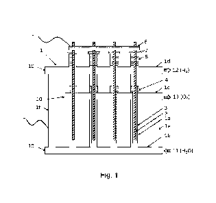
Turning to the drawings, with particular reference to Figures 1-3, there is
shown
an embodiment of a high-pressure electrolytic cell unit, comprising four
parallel electrolytic
cells, wherein the unit is made up from an assembly of three horizontal and
four vertical
interconnected tubes 1 a, lb, lc, Id, the latter arranged in a row, as well as
two additional
vertical tubes le and if, all made from an electrically conductive metal,
constituting an
electrically conductive body 1 which encloses the pressurized containment for
the electrolyte
and gases. An inlet 11 for liquid electrolyte or water is provided at the
lower horizontal tube
of the body and two gas outlets 12, 13 are provided at two upper horizontal
tubes Id and
CA 03237384 2024- 5-6
WO 2023/085938
PCT/NL2022/050648
12
lc, for exiting the produced gases hydrogen and oxygen, respectively. The body
of 1 is
connectable to a source of DC electricity, in this embodiment an anode (+).
The multiple
vertical tubes are represented by reference sign 1 a. These tubes each contain
an
electrolysis cell, enclosing a counter electrode 2, in this embodiment defined
as cathode (-),
which is situated centrally in the vertical tubes la. The lower horizontal
tube lb connects
the vertical tubes la at their lower outer ends and provides a uniform
distribution of the
electrolyte over the multiple cells which form part of the electrolytic cell
unit. The second
upper horizontal tube lc and the first horizontal tube id are located at
neighbouring distance
at the upper part of the vertical tubes la and are interconnected with the
vertical tubes,
comprising the oxygen and hydrogen separation (separating the electrolyte and
the gas)
and collecting headers. The tubes le and If are the downcomers, returning the
excess
electrolyte from the horizontal headers lc and Id, respectively. Cylindrical
membranes 3
are positioned concentrically around the central electrodes 2 and are
supported by
membrane support and sealing fittings 4, which are rigidly fitted in the
vertical tubes la
between the horizontal headers lc and Id. The central electrodes 2 are
arranged in the
vertical tubes la and supported by pressure tight and electrically isolated
fittings 5. The
conductive connecting profile 6 electrically interconnects the parallel
arranged counter
electrodes 2 at the top of the assembly, outside the electrolytic cell unit 1.
The electrically
isolating rings 7 isolate the body of the electrolytic cell unit 1 from the
electrodes 2 and the
conductive connecting profile 6.
Figure 4 shows the upper part of an electrolytic cell in more detail, in
particular
the relative arrangement between the body 1, the separation membrane 3 and the
support
and sealing fitting 4, and the electrode 2a, the electrode isolation 2b, the
electrode sealing
fitting 5 and the isolating ring 7.
Figure 5 shows at the left-hand side a schematic of a cell of a prior art
stacked
type electrolyzer, whereas at the right-hand a cell of the current invention
is shown, i.e. a
cross section of a vertical tube la with central electrode 2 and membrane 3.
Figure 6 shows a 3-dimensional view of an embodiment of a of high-pressure
electrolysis unit, as described in Figures 1-3, with 17 electrolytic cells in
parallel.
Figure 7 shows a schematic view of four high-pressure electrolytic cell units,
described in the previous figures, which are connected in series. The body 1
of one unit is
connected to the central electrodes 2 of the neighbouring unit by various
types of electrical
connecting profiles 6a, 6b and 6c. The bodies of the individual units are each
electrically
isolated by electrically isolating pads 8.
CA 03237384 2024- 5-6
WO 2023/085938
PCT/NL2022/050648
13
Figure 8 is a perspective view of an embodiment of an electrolyzer with
multiple
(16) high-pressure electrolysis units in a serial arrangement, together with a
cooling and
drying unit for the generated gases connected thereto;
Figure 9 is a scheme of a part of an electrolytic plant module showing the
electrolyzer of Fig. 8 and a cooling and drying unit, the device comprising a
feeding conduit
41 for (demin) water, main extraction conduit 43 of the reaction product
hydrogen, and main
extraction conduit 42 of the oxidation reaction product (oxygen). Also shown
are the feeding
conduits 44 for cooling medium. This scheme allows designing one or more
modules for the
feeding of each unit of cells in order to cover the needs of current and
voltage according to
the statements of the invention.
Figure 10 shows an isometric picture of the embodiment of the invention
including the cooling and drying system.
Figure 11 shows a schematic view of the embodiment of the invention including
the cooling and drying system, comprising the heat exchangers 51, 52, and 53
for hydrogen
54 and 55 for oxygen, external cooling system 57 and pressure reduction
station 56.
Operation
The empty racks, unit(s) will be filled with electrolyte (first filling, the
electrolyte
being a solution of 25 - 30% potassium hydroxide in demineralized water) with
all venting
devices in open position, until a maximum level in the racks has been secured.
Then the electrolysis process is started by connecting the unit to an
electrical
DC source and creating a voltage drop over every single electrolysis cell of 2-
3 V. Hydrogen
gas will be produced at the surface of the center electrode (cathode) and
oxygen will be
produced at the inner surface of the surrounding vertical tube (anode). The
gases produced
will rise to and collected into the first upper and the second upper
horizontal tube,
respectively, and subsequently be blown off to the environment. After some
time the venting
devices will be closed when all downstream volume has been purged by the
produced gases
and no air is remaining in the downstream system. Pressure will build up in
the system as
the volumes of the produced gases are far more larger than the converted water
volume.
Natural circulation via the downcomers will support the removal of the
produced
gases from the electrolytic cell area and the collection of the gases in the
headers.
When the operational pressure has been reached the gas pressure control
system will blow off the excess gases to the downstream systems, e.g. storage
and/or pipe
line system. The converted amount of water will be made up by demineralized
water when
the water level reaches low or controllable level.
The produced hydrogen and oxygen gases will be cooled down by a cooling
medium, e.g. cooling water. After cooling, the oxygen gas pressure will be
reduced to
CA 03237384 2024- 5-6
WO 2023/085938
PCT/NL2022/050648
14
atmospheric pressure, resulting in another temperature reduction due to the
thermodynamic
behavior of oxygen. The cold oxygen at ambient pressure is then used to cool
down the still
pressurized hydrogen even further.
The cooling devices are designed such that condensed water vapor will run back
into the electrolyzer cells.
Upon cooling the hydrogen gas as described it will be dried to a saturation
temperature below atmospheric conditions, thereby preventing condensation of
water vapor
in the downstream systems.
From the foregoing description, a person skilled in the art can easily
ascertain
the essential characteristics of the present invention, and without departing
from the spirit
and scope thereof, can make various changes and modifications to adapt it to
various
usages and conditions. These modifications and adaptations are therefore
deemed to fall
within the scope of protection of this invention as claimed in the appended
claims.
CA 03237384 2024- 5-6