Note: Descriptions are shown in the official language in which they were submitted.
WO 2023/140850
PCT/US2022/013162
DUAL MODE NON-INVASIVE BLOOD PRESSURE MEASUREMENT
FIELD
The present specification relates generally to monitoring physiological
parameters and
more specifically to methods and systems for obtaining blood pressure
measurements and/or
monitoring blood pressure using measurements from a non-invasive blood
pressure (NIBP)
device.
BA CKGROUND
Non-invasive blood pressure (NIBP) is an important physiological parameter
measured
in nearly every bedside monitor that is sold world-wide. For ambulatory blood
pressure (ABP)
measurements, NIBP measurement capability is deployed within small wearable
recorders to
obtain serial measurements on patients over the course of their daily
activity. Referring to FIG.
1, a conventional ambulatory blood pressure measurement system 100 is shown.
The system
100 comprises a cuff 115, a tubing 110 that places an air bladder within the
cuff 115 in air
communication with an air pump positioned within a housing 105. Valves 120 are
positioned
to be able to selectively release air from the cuff 115 air bladder. The
housing 105 further
comprises a measurement system that detects pressure oscillations emanating
from the cuff 115
and generates a blood pressure measurement, comprising a diastole measurement
and systole
measurement. Diastole and systole refer to when the heart muscles relax and
contract, with the
period of relaxation being diastole and the period of contraction being
systole, and the balance
there-between determines a person's blood pressure.
Traditional NIBP measurements are obtained by rapidly inflating a flexible
cuff, such
as cuff 115 in FIG. 1, positioned around a limb of a patient. The rapid
inflation is achieved
using a pump to direct air into the cuff and the pump action is maintained
until the cuff pressure
is elevated to pressure level that is significantly above a standard blood
pressure systole value
and is sometimes identified by monitoring the patient's pulse and continuing
to inflate the cuff
to about 30 mm Hg above the point where the patient's pulse disappears. In
measurements
made using the oscillometric method, the patient's pulse does not actually
disappear as it does
in measurements made using the auscultatory method, which are performed by
clinicians with
a stethoscope. In some devices, the rapid inflation is achieved using a pump
to direct air into
the cuff, maintaining the pump action until the cuff pressure is elevated to a
pressure level that
is significantly above a previous measurement. In an example, if the last
measurement for a
patient was 120/80, the device inflates to the previous systolic plus 35 mm Hg
(thus, 155 mm
1
CA 03238639 2024-5- 17
WO 2023/140850
PCT/US2022/013162
Hg in this example). Once that increased pressure level is reached, the air
pump is turned off,
and the cuff is deflated in a controlled, step-down marmer. The cuff pressure
is lowered in small
pressure increments of typically at or around 8 millimeters mercury (mm Hg).
At each step,
measurements of pressure oscillations are made. Oscillations in the cuff
corresponding to
arterial pulses are then analyzed to determine blood pressure. The point of
maximal oscillation
corresponds to the mean intra-arterial pressure. During step deflate,
measurements are taken
for a target blood pressure that is either a default value depending on
patient type or is based
on a previous measurement.
Conventional NIBP devices typically include two valves that control the
bleeding of air
from a cuff In general, each valve is configured such that, when activated,
the valve is in a
closed position, thereby making the cuff air-tight, and, when power is removed
or when the
valve is deactivated, the valve transitions to an open state, thereby allowing
air to flow out of
the cuff Two valves are typically used because the first one functions as the
actual deflation
mechanism while the second valve functions as a backup in case the first valve
fails.
Additionally, the second valve may be used to provide a mechanism for clearing
or removing
the pressure from the cuff more rapidly upon completing the measurement.
Another approach to NIBP measurements is to use an "on-inflate" system. In an
on-
inflate system, measurements are made during cuff inflation, as opposed to a
conventional step-
deflate NIBP system in which measurements are only made after the cuff has
been frilly inflated
and is in the process of being deflated. A specialized pneumatic arrangement
between valves
and a pump enables controlled inflation and deflation of an interior chamber
in the cuff. The
principal advantages of on-inflate measurement include faster measurement,
lower maximum
cuff pressure, and reduced ambient noise from the pump. Since the pump
operates at a reduced
RPM to operate the device and inflate the cuff slowly, the pump is also
relatively quiet
compared with a traditional full speed measurement. These features, both alone
and in
combination, provide a more comfortable experience for the patient because the
"squeeze" on
the arm is reduced in intensity and duration and the loud noise from the pump
during full-speed
operation is minimized. The on-inflate measurement methods and devices are
less traumatic
for use with children, and patients with frail physical structures. In
addition, clinicians are able
to obtain faster measurements, typically on the order of 30% faster.
While on-inflate NIBP devices are able to provide the benefits of speed and
comfort to
patients, for small cuff sizes, such as small adults (cuff size of 12 cm x 22
cm) or children
(ranging from 4 cm x 8cm to 9 cm x 18 cm), the task of controlling the speed
of inflation is
challenging. The rate of inflation may be varied by adjusting the speed or
revolutions per
2
CA 03238639 2024-5- 17
WO 2023/140850
PCT/US2022/013162
minute (RPM) of the pump. The pump speed may be further modified using the
applied drive
voltage across the terminals of the pump since the pump RPM increases with an
increase in the
applied voltage. A voltage threshold is associated with a current pressure in
each NIBP device,
below which the pump is unable to turn or is in a 'deadhead' state. Any
voltage applied to
about 10% above the threshold may be considered to induce a low RPM for the
pump. With
smaller cuffs, the pump speed is required to be low to give an effective
inflation rate of 3 to 6
mm Hg per pulse. At this low flow rate, the pump tends to be unstable because
an applied
voltage is near a lower limit of how slow the pump can turn. The instability
makes it
challenging to control the inflation rate of small cuffs reliably.
Additionally, when the pump
RPM is low, meaning that is it is within range of 10% above the deadhead
threshold, frequency
of the pump perturbations approaches the upper frequency of the range of
interest for pulse
identification (10 Hz) and the noise from the pump begins to obscure the
signal of interest
(pulses). Therefore, the magnitude of perturbations to the pressure signal
from the pump can
obscure the pulse signal that are being attempted to be measured with the NIBP
device.
Therefore, there is a need for methods and systems of non-invasive blood
pressure
measurement that are able to overcome the one or more deficiencies of the
current standard
and on-inflate NIBP devices. In particular, there is a need for NIBP systems
that can operate at
low flow rates while maintaining a substantially constant inflation rate.
There is also a need
for NIBP systems that can reliably generate the requested constant flow rate
for small cuff
sizes. There is also a need for NIBP systems that minimize frequencies of pump
perturbations
approaches when operating a pump at an applied voltage that is at or near the
lower voltage
limit for the pump.
SUMMARY
The following embodiments and aspects thereof are described and illustrated in
conjunction with systems, tools and methods, which are meant to be exemplary
and illustrative,
not limiting in scope.
The present specification discloses a blood pressure monitoring system,
comprising: a
housing; a controller located within the housing; a pump located within the
housing, wherein
the pump is in electrical communication with the controller and wherein the
controller is
configured to activate the pump and deactivate the pump; a pressure sensor and
analysis system
located within the housing, wherein the pressure sensor and analysis system is
in data
communication with the controller; a first hose defined by a first inner
diameter; a first cuff
configured to connect to the first hose; a second hose defined by a second
inner diameter; a
3
CA 03238639 2024-5- 17
WO 2023/140850
PCT/US2022/013162
second cuff configured to connect to the second hose; a cuff connector adapted
to be coupled
to the first hose or the second hose; and at least two valves positioned
within the housing,
wherein a first valve of the at least two valves is configured to enable a
first air flow rate and a
second valve of the at least two valves is configured to enable a second air
flow rate, wherein
the controller is adapted to operate at least one or both of the first and
second valves based on
whether the cuff connector is coupled to the first hose and the first cuff or
the cuff connector
is coupled to the second hose and the second cuff.
Optionally, the first inner diameter of the first hose is greater than the
second inner
diameter of the second hose. Optionally, the cuff connector is coupled to the
first hose or the
second hose through at least one adapter. Optionally, the first cuff is
configured to fit around a
limb of an adult patient or a pediatric patient. Optionally, the second cuff
is configured to fit
around a limb of a neonate patient.
Optionally, at least one of the first cuff or the second cuff is configured to
wrap around
a limb of a patient wherein at least one of the first cuff or the second cuff
is in air flow
communication with the pump and configured to receive air when the pump is
activated by the
controller.
Optionally, the first valve and the second valve are identical, and a
restrictor is
configured to restrict air flow in the flow path of the first valve.
Optionally, the first valve is
smaller than the second valve so that air flow through the first valve is
restricted compared to
air flow through the second valve. Optionally, during a deflation of the
second cuff, the
controller is configured to cause the first valve to be open for at least a
portion of said deflation.
Optionally, during a deflation of the second cuff, the controller is
configured to cause the first
valve and the second valve to be open for at least a portion of said
deflation.
Optionally, the cuff connector comprises a female rectus connector.
Optionally, the blood pressure monitoring system further comprises a monitor
to
display information about at least one of a blood pressure measurement, a
status of the first
hose connected to the first cuff, a status of the second hose connected to the
second cuff, a
status of the first cuff or the second cuff being coupled to the cuff
connector, and/or whether
an adapter is attached to the cuff connector.
The present specification also discloses a method of determining a blood
pressure of a
patient using a non-invasive blood pressure (NIBP) device, wherein the NIBP
device comprises
a controller positioned within a housing, a cuff connector, a first hose
having a first inner
diameter, adapted to be connected to a first cuff and configured to be coupled
to the cuff
connector, a second hose having a second inner diameter, adapted to be
connected to a second
4
CA 03238639 2024-5- 17
WO 2023/140850
PCT/US2022/013162
cuff and configured to be coupled to the cuff connector, a pump in fluid
communication with
the cuff connector, and at least two valves where a first valve of the at
least two valves is
configured to enable a first air flow rate in an open configuration and a
second valve of the at
least two valves is configured to enable a second air flow rate in an open
configuration, wherein
the first air flow rate is lower than the second air flow rate, the method
comprising: coupling
at least one of the first cuff or the second cuff to the cuff connector;
applying the first cuff or
the second cuff to a limb of a person; operating the controller to determine
whether the cuff
connector is coupled to the first cuff or the second cuff; operating the
controller to activate the
pump, wherein, upon activation, the pump directs air into the first cuff or
the second cuff
positioned on the limb of the person; and operating the controller to open
and/or close the first
valve and/or the second valve based on whether the first cuff or the second
cuff is coupled to
the cuff connector and based on whether the controller is causing the first
cuff to inflate or
deflate or the second cuff to inflate or deflate.
Optionally, the method further comprises operating the controller to determine
if the
first hose is connected to the first cuff or if the second hose is connected
to the second cuff.
Optionally, the first inner diameter of the first hose is greater than the
second inner
diameter of the second hose.
Optionally, the cuff connector is coupled to the first hose or the second hose
through at
least one adapter.
Optionally, the first cuff is configured to fit around a limb of an adult
patient or a
pediatric patient and the second cuff is configured to fit around a limb of a
neonate patient.
Optionally, during an inflation of the first cuff, wherein the first cuff is
fit around the limb of
the adult patient, the controller is configured to cause the first valve and
the second valve to be
closed during said inflation. Optionally, wherein when the determining the
blood pressure is
performed during an inflation of the first cuff, and wherein the first cuff is
fit around the limb
of the pediatric patient, the controller is configured to cause the first
valve to be at least partially
open and the second valve to be closed during said inflation. Optionally,
wherein when the
determining the blood pressure is performed during a deflation of the second
cuff, the controller
is configured to cause the first valve to be opened at least during a portion
of said deflation.
Optionally, when the determining the blood pressure is performed during a
deflation of the first
cuff, the controller is configured to cause the first valve and the second
valve to be opened.
Optionally, the method further comprises detecting pressure oscillations in
the first cuff
or the second cuff during one of the inflation or the deflation of the first
cuff or the second cuff
to determine a blood pressure of the person.
5
CA 03238639 2024-5- 17
WO 2023/140850
PCT/US2022/013162
Optionally, the method further comprises, when the controller is causing the
first cuff
to inflate or the second cuff to inflate, identifying an anomaly and using the
controller to cause
at least one of the first valve or the second valve to close during a step-
deflation process.
Optionally, operating the controller to determine if the first cuff is coupled
to the cuff connector
or the second cuff is coupled to the cuff connector comprises: opening the
first valve; operating
the pump for a first period of time; measuring a first amplitude of an air
pressure pulse
generated by the operating the pump after the first period of time; operating
the pump for a
second period of time; measuring a second amplitude of an air pressure pulse
generated by the
operating the pump after the second period of time; calculating a function of
the first amplitude
and the second amplitude; and determining, based on an output of the function,
at least one of
whether at least one of the first hose or the second hose is coupled to the
cuff connector,
whether at least one of the first hose or the second hose is kinked, whether
the first hose is
connected to the first cuff, or whether the second hose is connected to the
second cuff
Optionally, the function is an average of the first amplitude and the second
amplitude.
Optionally, each of the first time period and the second time period ranges
from 10 milliseconds
to 100 milliseconds and is preferably 50 milliseconds. Optionally, the method
further
comprises a time gap between the first period of time and the second period of
time. Optionally,
operating the pump comprises operating at a duty cycle in a range equal to 90%
to 100%.
Optionally, determining if the first hose is connected to the first cuff or if
the second hose is
connected to the second cuff comprises: opening the first valve and the second
valve for the
first time period; operating the pump at a duty cycle in a range of 30% to 50%
after the first
time period; measuring the first amplitude; and determining, based on the
first amplitude, at
least one of whether the first hose is connected to the first cuff or whether
the second hose is
connected to the second cuff Optionally, the determining comprises concluding
that the first
hose is connected to the first cuff if the amplitude has a first value or the
second hose is
connected to the second cuff if the amplitude has a second value, wherein the
first value is less
than the second value.
The aforementioned and other embodiments of the present specification shall be
described in greater depth in the drawings and detailed description provided
below.
BRIEF DESCRIPTION OF THE DRAWINGS
These and other features and advantages of the present specification will be
appreciated,
as they become better understood by reference to the following detailed
description when
considered in connection with the accompanying drawings, wherein:
6
CA 03238639 2024-5- 17
WO 2023/140850
PCT/US2022/013162
FIG. 1 depicts a conventional NIBP system;
FIG. 2 provides a schematic diagram of an exemplary blood pressure measurement
system in accordance with one embodiment of the specification;
FIG. 3A is a flowchart illustrating an exemplary sequence of operations
performed to
confirm cuff connection, in accordance with the embodiments of the present
specification;
FIG. 3B is a flowchart showing a first set of steps in an exemplary blood
pressure
measurement method in accordance with one embodiment of the invention; and
FIG. 3C is a flowchart showing a second set of steps in an exemplary blood
pressure
measurement method in accordance with one embodiment of the invention.
DETAILED DESCRIPTION
In various embodiments, the present specification provides methods and systems
for
monitoring physiological characteristics of a patient using a non-invasive
blood pressure
(NIBP) monitoring device. The NIBP device performs the measurement in two
modes. The
mode is selected on the basis of the patient. The device verifies that the
selected mode
corresponds to the type of cuff that is used for the selected patient. In
operation, an adapter
with two hoses is removably attached to a cuff connector of the NIBP device. A
first hose is
configured to connect to a cuff for NIBP measurement of an adult/pediatric
patient, whereas
the second hose is configured to interface with a cuff for a neonate patient.
Each hose has a
different inner diameter that offers different resistance to air flow through
them. The different
resistance is detected by the NIBP system to determine/confirm if an
adult/pediatric type
patient is connected or a neonatal type patient is connected. Before every
measurement, a
check is performed to confirm if an adapter is present and if it is, then to
confirm that it is
connected to the correct type of cuff that matches the patient settings on a
monitor integrated
with the NIBP device. If the adapter is not attached or the wrong hose is
attached to a cuff,
then a measurement will not be taken and a message is communicated to the user
about the
mismatch.
Additionally, once the NIBP device is enabled to identify whether the patient
is an
adult/pediatric patient or a neonatal patient, the measurement method is
adjusted to measure
using either a step-deflate process or an on-inflate process. Therefore,
embodiments of the
NIBP system can perform measurements with both normal adult/pediatric cuffs in
one mode
and for neonatal cuffs which are very small, in another mode. Measurements in
the neonatal
mode are performed using a conventional inflation and step-deflation process.
In one
embodiment, a pneumatic arrangement of the NIBP device has a specially
designed, restricted
7
CA 03238639 2024-5- 17
WO 2023/140850
PCT/US2022/013162
flow-path configuration that enables a controlled deflation appropriate for
small neo-natal cuff
sizes. The restricted flow-path makes it easier to control the step-deflation
process and obtain
accurate pressure control for the small neonatal cuffs. In addition, a faster
operation of the
pump also causes pneumatic noise from the pump to shift to a higher frequency
and away from
the pulse signal of interest where it can be more effectively filtered out.
Measurements in the
adult/pediatric mode can be performed either using on-inflate or step-deflate
process of NIBP
measurement. In some embodiments, the on-inflate measurement mode is
preferably used for
speed and comfort and the step-deflate mode is preferred for adult/pediatric
measurements as
a fallback if the on-inflate measurement is unsuccessful.
The present specification is directed towards multiple embodiments. The
following
disclosure is provided in order to enable a person having ordinary skill in
the art to practice the
invention. Language used in this specification should not be interpreted as a
general disavowal
of any one specific embodiment or used to limit the claims beyond the meaning
of the terms
used therein. The general principles defined herein may be applied to other
embodiments and
applications without departing from the spirit and scope of the invention.
Also, the terminology
and phraseology used is for the purpose of describing exemplary embodiments
and should not
be considered limiting. Thus, the present invention is to be accorded the
widest scope
encompassing numerous alternatives, modifications and equivalents consistent
with the
principles and features disclosed. For purpose of clarity, details relating to
technical material
that is known in the technical fields related to the invention have not been
described in detail
so as not to unnecessarily obscure the present invention.
In the description and claims of the application, each of the words "comprise"
"include"
and "have", and forms thereof, are not necessarily limited to members in a
list with which the
words may be associated. It should be noted herein that any feature or
component described
in association with a specific embodiment may be used and implemented with any
other
embodiment unless clearly indicated otherwise.
In some embodiments, the system includes at least one processor (not shown) to
control
the operation of the entire system and its components. It should further be
appreciated that the
at least one processor is capable of processing programmatic instructions, has
a memory
capable of storing programmatic instructions, and employs software comprised
of a plurality
of programmatic instructions for performing the processes described herein. In
one
embodiment, the at least one processor is a computing device capable of
receiving, executing,
and transmitting a plurality of programmatic instructions stored on a volatile
or non-volatile
computer readable medium. Thus, in various embodiments, a computing device may
be
8
CA 03238639 2024-5- 17
WO 2023/140850
PCT/US2022/013162
employed to receive and process data signals and may include an input/output
controller, at
least one communication interface and a system memory. The system memory may
include at
least one random access memory (RAM) and at least one read-only memory (ROM).
These
elements are in communication with the processor or central processing unit
(CPU) to enable
operation of the computing device.
In embodiments, the system is coupled to at least one display, which displays
information about at least one patient parameter and the operation of the
system, by means of
a GUI. The GUI also presents various menus that allow users to configure
settings according
to their requirements.
In various embodiments, the computing device may be a conventional standalone
computer or alternatively, the functions of the computing device may be
distributed across a
network of multiple computer systems and architectures. In some embodiments,
execution of
a plurality of sequences of programmatic instructions or code, which are
stored in one or more
non-volatile memories, enable or cause the CPU of the computing device to
perform or enable
various functions, processes and algorithms, such as, for example, obtaining
blood pressure
measurements and/or monitoring blood pressure using measurements from a non-
invasive
blood pressure (NIBP) device. In alternate embodiments, hard-wired circuitry
may be used in
place of, or in combination with, software instructions for implementation of
the processes of
systems and methods described in this application. Thus, the systems and
methods described
are not limited to any specific combination of hardware and software.
In embodiments, the present specification provides an NIBP device configured
to
interface with a cuff to measure physiological parameters of an adult or a
pediatric patient, as
well as a relatively smaller cuff that is configured for a neonatal patient.
The device is further
configured to enable BP measurements of the different types of patients using
different
methods.
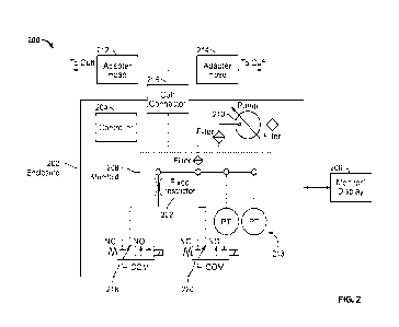
FIG. 2 illustrates an NIBP device or system 200 configuration in accordance
with some
embodiments of the present specification. A controller 204, which comprises
one or more
electrical circuits, memory, and processors integrated on to one or more
printed circuit boards,
may be positioned in an enclosure or a housing 202. A display or a monitor
206, such as a
touch-screen display, may also be integrated with the system 200. In some
embodiments, the
display 206 may enable a user to input patient settings, to select a mode of
operation for the
system 200, display the mode selected by the system 200, and communicate
anomalies or
matches that are identified by the system 200, in addition to the measurements
monitored by
the system 200. The housing 202 further comprises an air pump 210 and a
pressure sensor and
9
CA 03238639 2024-5- 17
WO 2023/140850
PCT/US2022/013162
analysis system 213, which may also comprise one or more electrical circuits,
memory, and
processors integrated on to one or more printed circuit boards. Both of the
air pump 210 and
pressure sensor and analysis system 213 are in electrical communication with
the controller
204 and monitor 206. The pressure sensor and analysis system 213 is located
within a manifold
208 that provides a path for air pumped by the pump 210 to reach at least two
valves 218 and
220. The pressure sensor and analysis system creates an analog voltage
corresponding to the
air pressure that develops in the manifold 208, which analog voltage is
sampled by analog to
digital converters so as to provide a measure of the pressure. The pressure
sensor and analysis
system 213 is also in communication with the controller 204. The controller
204 is configured
to execute an on-inflation blood pressure management process, as described
below.
The NIBP system 200 includes a single front panel connector port 216 (which in
an
embodiment is a female rectus connector port), a first adapter hose 212 and a
second adapter
hose 214. In embodiments, the proximal end of either the first adapter hose
212 or the second
adapter hose 214 is connected to a port of connector 216. In an embodiment, a
distal end of
first adapter hose 212 is configured to connect to a cuff for adult/pediatric
patients, whereas a
distal end of second adapter hose 214 is configured for interfacing with a
cuff for neonatal
measurement. In embodiments, because neonatal cuffs have different pressure
safety limits
(approximately 150 mmHg versus 300 mmHg for adults) and a different adapter at
the cuff
end, second adapter hose 214 is used for neonatal use while first adapter hose
212 is for adult
use. In embodiments, the adapter positioned on the neonatal cuff has a smaller
diameter than
that on the adult cuff Neonatal adapter hose 214 has a smaller inner diameter
and is narrower
than the adult adapter hose 212 which has a relatively larger inner diameter.
In some
embodiments, the first adapter hose 212 and second adapter hose 214 have equal
lengths. In
some embodiments, the first adapter hose 212 and second adapter hose 214 have
lengths that
are not equal relative to one another. In some embodiments, the first adapter
hose 212 and the
second adapter hose 214 each have a length ranging from 6 feet to 10 feet. In
embodiments,
first adapter hose 212 and second adapter hose 214 plug into the common cuff
connector port
216 on the front panel of the system 200.
Adapter hose 212 and adapter hose 214 have different inner diameters and
present
different flow resistances to the system 200. In an embodiment, adapter hose
212, for use with
adults, has an inner diameter of 1/8 inch. In an embodiment, adapter hose 214,
for use in a
neonatal setting, has an inner diameter of 1/16 inch. Prior to operating the
system 200 for a
measurement, a check is performed by pumping air from pump 210 and measuring
the flow
resistance, which is measured by the pressure sensor and analysis system 213.
In embodiments,
CA 03238639 2024-5- 17
WO 2023/140850
PCT/US2022/013162
NIBP system 200 has at least two pressure transducers to be "fault tolerant-
to ensure that if
one transducer fails, the second (backup) transducer does not allow unsafe
pressures to be
applied to the patient. The measured flow resistance is taken as an indicator
that a cuff is
appropriately connected to the adapter, and the type of the hose (212 or 214)
to which that cuff
is connected. The type of adapter hose is used as the basis to either select a
mode of operating
the system 200 or to validate a mode selected by the user in patient settings.
If the system 200
detects that neither adapter hose 212 nor adapter hose 214 is attached to a
cuff, or the wrong
type of adapter hose is attached, then a measurement is not taken. A message
is displayed on
the monitor 206 to inform the user regarding the mismatch.
Upon connecting the housing 202 to the cuff, via cuff connector 216, the pump
210 is
activated to direct air into the cuff. The pump 210 is controlled by
modulating a voltage that
is applied across the terminals of the pump 210. As the duty cycle is
increased the pump 210
is given more -throttle- by increasing the applied voltage. Inflation of the
cuff is controlled
with a first valve 218 and a second valve 220, which, in an embodiment are
high flow valves.
First valve 218 and second valve 220 are provided in the path of the pumped
air, within
manifold 208, from the pump 210 to the cuff connector 216 that directs air
into the cuff
connected via either first adapter hose 212 or second adapter hose 214. In
some embodiments,
the first valve 218 and second valve 220 have identical structures. In an
embodiment, an inlet
of first valve 218 is modified with a flow restrictor 222, which enables a now
restricted first
flow valve 218 to perform similarly to a valve designed with a narrow orifice
for more precise
control of flow through the first valve 218. In some embodiments, one of the
valves, such as
first valve 218 is configured with a narrow flow path relative to the high-
flow valve 220. By
way of example, when unrestricted, first valve 218 is a high flow valve and
has an inner
diameter ranging from 0.04 to 0.08 inches, and preferably approximately 0.066
inches and
when restricted, the inner diameter of first valve 218 is reduced to a
diameter ranging from
0.005 inches to 0.020 inches, and preferably approximately 0.012 inches.
The cuff, connected through connector 216, is rapidly inflated at a full speed
of the
pump 210, to a pressure of 50 mmHg. In an embodiment, 12V pumps are used,
therefore 12V
are applied to the pump to obtain maximum RPM. A lower effective applied
voltage below
12V would operate the pump at a lower speed. During inflation, the pressure
sensor and
analysis module 213 captures a pressure waveform at 220 Hz. The module obtains
a derivative
of the pressure, and subsequently applies a low pass filter to create a
derivative waveform with
a frequency below 10Hz. Several features are extracted from the pressure and
the low pass
11
CA 03238639 2024-5- 17
WO 2023/140850
PCT/US2022/013162
filtered derivative waveform. In embodiments, some exemplary features that are
extracted are
presented in Table 1:
Table 1
S No. Feature Details
1 Time 40 time to hit 40 mmHg from 30 mmHg
2 Time 50 time to hit 50 mmHg from 40 mmHg
3 Sum40to50 sum (pressure from 40 mmHg to 50 mmHg)
4 Sum30to40 sum(pressure from 30 mmHg to 40 mmHg)
LPF3 Oto40 sum(low pass filtered derivative from pressure > 30 mmHg and <
40
mmHg) / (time to hit 40 mmHg from 30 mmHg)
6 LPF40to50 sum(low pass filtered derivative from pressure
> 30 mmHg and < 40
mmHg) / (time to hit 40 mmHg from 30 mmHg)
5 Hose Detection and Cuff Size Determination
FIG. 3A illustrates an exemplary method, implemented by system 200, for
identifying
a connection of either adapter hose 212 or adapter hose 214 and thus, a type
of cuff connected
thereto. The presence and/or type of cuff attached can be detected by
detecting the presence
and type of an adapter hose. The adapter hose detection process is initiated
during the start of
each blood pressure measurement. When a measurement is requested, the system
automatically checks to make sure a hose is present and that it matches the
patient type, as
described below. If there is no hose, a first error-type message is displayed
and no
measurement is taken. If the wrong adapter hose is detected, a second error-
type message is
displayed. The hose detection process involves a primary hose detection phase
and a secondary
hose detection phase. As stated earlier, second adapter hose 214 is relatively
smaller than first
adapter hose 212, where the second adapter hose 214, having a smaller inner
diameter is
configured to interface with a neonate cuff First adapter hose 212 is
configured to interface
with a cuff used in adult or pediatric NIBP.
Referring simultaneously to FIGS. 2 and 3A, at step 302, the primary phase is
initiated
by opening first valve 218, fitted with flow restrictor 222, and closing valve
220, which, in an
embodiment, is a high flow valve. In embodiments, first flow valve 218 fitted
with flow
restrictor 222 is referred to as a restricted valve. At step 304, a first
pressure pulse is generated
within manifold 208 by operating the pump 210 at a 100% duty cycle for a first
time period.
In an embodiment, the pump 210 is operated for a first time period ranging
from 10
milliseconds to 100 milliseconds, and preferably 50 milliseconds (ms). At step
306, a first
12
CA 03238639 2024-5- 17
WO 2023/140850
PCT/US2022/013162
pulse amplitude of the first pulse generated is measured after waiting a short
duration, as the
pressure continues to rise for that duration, which is roughly equivalent to a
couple of samples
after the pump 210 is turned off In some embodiments, the time period for
waiting is in a
range of 20 to 40 ms. The measured pressure, measured by the pressure sensor
and analysis
system 213, is indicative of flow resistance resulting from back pressure
generated by either
first adapter hose 212 or second adapter hose 214, which is connected to a
cuff on its distal
end. At step 308, after the amplitude of the first pulse is measured, the
system 200 generates
a second pulse by operating the pump for a second time period, ranging from 20
milliseconds
to 100 milliseconds, and preferably 50 milliseconds (ms). In some embodiments,
the first and
second time periods are of equal duration, which is preferably 50 ms. At step
310, an amplitude
of the second pulse generated is measured after waiting a short duration after
the pump 210 is
turned off In some embodiments, the short duration is in a range of 20 to 40
ms. At step 312,
the controller processes the recorded amplitude of the first pulse and the
second pulse to obtain
an average pulse amplitude. The average pulse amplitude value is used to
determine a type of
adapter hose and/or a state of hose that is connected to cuff connector 216.
In some embodiments, an average value of greater than 40 mm Hg indicates that
the
connected hose is kinked. In embodiments, an average value ranging between 20
and 40
mmHg indicates that second adapter hose 214 (neonatal) is connected. Further,
an average
value that is less than 20 mmHg and greater than or equal to 3.5 mmHg
indicates that first
adapter hose 212 (adult) is connected. Additionally, an average value of less
than 3.5 mmHg
indicates that no hose is connected to connector 216. When no hose is
connected, the
amplitudes of the first pulse and the second pulse, used for calculating the
average, agree within
1 mmHg. When first adapter hose 212 is connected, the amplitudes of the first
pulse and the
second pulse, used for calculating the average, agree within 10 mm Hg. When
second adapter
hose 214 is connected, the amplitudes of the first pulse and the second pulse,
used for
calculating the average, agree within 10 mm Hg. It should be noted that a
large difference
between the amplitudes of the first pulse and second pulse may indicate that
the recorded data
is unreliable. In this case, the primary phase of the hose detection process
may be repeated. In
some embodiments, the primary phase of the detection process is repeated for a
maximum of
two times after which a failure to identify the cuff/hose combination is
reported. At step 314,
the average pulse amplitude is used to determine whether either of first
adapter hose 212 or
second adapter hose 214 is connected to a cuff at its distal end, and if
connected, which
hose/cuff combination has been detected.
13
CA 03238639 2024-5- 17
WO 2023/140850
PCT/US2022/013162
In embodiments, the average pulse amplitude is compared to pre-defined
threshold
values of pulse amplitude that are stored by the controller 204. In some
embodiments, the pre-
defined threshold values are derived by measuring the amplitudes of the pulses
in prototypes
and by ensuring an adequate margin to reasonably identify all the states. The
first pulse
amplitude and the second pulse amplitude may also be compared. In embodiments,
controller
204 is configured to compare the average pulse amplitude to pre-defined
threshold values for
pulse height/amplitude to identify whether the first adapter hose 212 or the
second adapter hose
214 is connected to the cuff The neonate adapter hose 214 results in a larger
pulse amplitude
when compared to the adult adapter hose 212, due to the smaller volume
afforded for air flow
as a result of its smaller inner diameter.
Additionally, in another scenario, if neither first adapter hose 212 nor
second adapter
hose 214 is connected to a cuff, the average pulse amplitude recorded will
have a very small
value. In yet another scenario, if there is a kink or other anomaly in either
first adapter hose
212 or second adapter hose 214, the average pulse amplitude recorded will be
of a large value.
Exemplary values for the various scenarios are noted above.
Once the connection and presence of a cuff is detected, the system 200
performs the
second phase. FIG. 3B is a flowchart illustrating an exemplary sequence of the
process
performed by system 200 in the second phase, in accordance with some
embodiments of the
present specification. At step 320, both first valve 218 and second valve 220
are opened
initially for a time period, whereafter both first valve 218 and second valve
220 are closed. In
embodiments, the time period may be within a range of 10 to 20 milliseconds
(ins). In one
embodiment, the first valve 218 and second valve 220 are opened for 15.6 ms.
At step 322,
pump 210 is pulsed at a duty cycle in a range of 30% to 50%, and preferably at
40%, while
valves 218 and 220 are open. At step 324, the pressure pulse amplitude that is
observed is
recorded. Al step 326, the recorded pulse amplitude is compared to the average
pulse amplitude
observed during the primary detection phase. As described above with respect
to FIG. 3A, the
first phase identifies whether a hose (first adapter hose 212 or second
adapter hose 214) is
connected. Here, the second phase is used to determine the type of hose (first
adapter hose 212
or second adapter hose 214) that is connected. At step 328, if the pulse
amplitude is smaller
than the average pulse amplitude measured in the primary phase, then a
"failure to detect" the
adapter hose is reported. Thus, if there is no agreement between the primary
and secondary
determinations, the measurement is aborted.
Additionally, a measurement is not completed if either adapter hose that is
being
measured is kinked or flawed, resulting in irregular or skewed back pressure.
In an
14
CA 03238639 2024-5- 17
WO 2023/140850
PCT/US2022/013162
embodiment, the user is informed by an audio, visual, or a combination of an
audio-visual alert.
The visual alert may be in the form of a message that is displayed on monitor
206. The user
may physically examine the hose to check whether a cuff is connected to a hose
and that it is
not kinked.
At step 330, if the pulse amplitude is equal to or greater than the average
pulse
amplitude of the primary phase, then the pulse is compared to pre-defined
thresholds to
determine one of several different cuff connections. In some embodiments, if
the pulse
amplitude is less than 25 mmHg then the connected hose is identified as first
adapter hose 212,
and if the pulse amplitude is greater than or equal to 25 mmHg then then
connected hose is
identified as second adapter hose 214. The adult adapter hose 212 results in a
pulse of lower
amplitude compared to that of the neonate adapter hose 214. At step 332, at
the end of the
secondary hose detection phase, the system 200 reports the type of adapter
hose identified. In
some embodiments, the process described in FIGS. 3A and 3B, is completed in
less than one
second. The system 200 then proceeds to NIBP measurement based on the type of
cuff that is
connected to it. The methods of measurement differ between first adapter hose
212/associated
cuff and second adapter hose 214/associated cuff
NIBP Measurement
If, upon completing the secondary phase of detection, it is determined that an
adapter
hose is connected to the corresponding cuff for the selected mode of
measurement (as provided
in the patient settings), then, at step 340, the measurement commences as
described in FIG. 3C.
FIG. 3C illustrates an exemplary method, performed by system 200, based on
identification of
the adapter hose and thus cuff type (small corresponding to a neonatal cuff
and connected to
second adapter hose 214, or large corresponding to an adult/pediatric cuff and
connected to
first adapter hose 212), in accordance with the embodiments of the present
specification.
At step 342, the patient type and adapter hose type are identified according
to the
process described in context of FIGS. 3A, 3B, and 3C. Referring simultaneously
to FIGS. 2
and 3C, if, at step 342, it is determined that hose 212 is connected to its
corresponding cuff for
an adult/pediatric patient, the method proceeds to step 344. At step 344, an
on-inflate
measurement of BP is performed. During the measurement, both valves 218 and
220 remain
closed. Since first adapter hose 212 is larger than second adapter hose 214
(wherein the second
adapter hose is designed for neo-natal patients), first adapter hose 212 may
support a range of
cuff sizes. First adapter hose 212 may have a corresponding cuff size ranging
from a small
cuff size for adults and pediatric patients or children, which is still larger
than the cuff sizes
CA 03238639 2024-5- 17
WO 2023/140850
PCT/US2022/013162
available for neo-natal patients to a relatively larger cuff size appropriate
for an adult.
Therefore, it is also desirable to be able to distinguish between an adult and
a pediatric patient
while connected to first adapter hose 212. The NIBP measurement method differs
for an adult
patient and for a pediatric patient. For smaller cuff sizes, such as for
pediatric use/children,
optionally in some cases, the restricted valve 218 is left open during on-
inflate measurement to
allow for better pump control.
As such, an additional step may be used to determine the size of the cuff
(whether adult
or pediatric), when connected to first adapter hose 212. A pediatric cuff has
a small cuff
volume relative to an adult cuff The distinction between an adult and a
pediatric cuff size is
determined based upon an amount of time it takes to inflate the cuff through
first adapter hose
212 from zero to a low target pressure. The longer the time it takes, the
larger the cuff, which
corresponds to an adult size cuff. If, at step 346, an anomaly is identified
in the measurement,
then the system 200 may optionally proceed to step 352 to perform a
measurement using step-
deflation, as a check method. The anomaly may be identified if the pressure
measurement is
irregular. At step 356, the measurement using the step-deflation method is
performed with
valve 218 closed and valve 220 closed until they are both opened to the next
"step" during the
measurement. When the measurement is completed, both valves 218 and 220 are
opened and
the pressure is released. In case there is no anomaly at step 346, the on-
inflate measurement
of step 344 is completed at step 350. As stated before, if the cuff size is
determined to be for
a child (pediatric), the on-inflate measurement is performed with the
restricted flow valve 218
open. Keeping valve 218 open simulates a "small leak" and allows the pump to
run a little
faster, where it is easier to control. In addition, the pump noise (pneumatic)
does not interfere
with the measurement. On the other hand, if the cuff size is determined to be
larger than for a
child (pediatric) then the restricted valve 218 is closed during the on-
inflate measurement. In
some embodiments, an algorithm is used to analyze the pressure pulse
amplitudes observed
during cuff inflation to determine blood pressure. In some embodiments, the
time it takes to
inflate the cuff is also monitored. In embodiments, a robust estimate of the
maximum pulse
amplitude is obtained, so that the measurement is reliable (assuming real
world conditions) and
is not a product of motion artifact or any other disturbance. In embodiments,
an estimate of
systolic pressure is determined where the pulse amplitude achieves
approximately 50% of the
pulse maximum. Similarly, diastolic pressure is estimated when the pulse
amplitude reaches
approximately 75% of its peak value.
However, if at step 342 it is identified that hose 214 is connected to its
corresponding
cuff for a neonate patient, the method proceeds to step 352 to initiate
measurement using step-
16
CA 03238639 2024-5- 17
WO 2023/140850
PCT/US2022/013162
deflation. Since the step-deflation measurement is for a neonate patient, at
step 358, first valve
218 is opened and second valve 220 is closed during the bleed steps of the
measurement, when
the air is enabled to leak or bleed out during a deflation step. The valve 218
that is left open
during the measurement of blood pressure is configured with a flow restriction
structure 222
positioned within the exhaust path of the valve 218. In some embodiments, the
exhaust path
of the valve 218 is configured with a controlled orifice, fitted with the
restriction structure 222,
which in turn enables control of the speed of inflation by limiting the amount
of air that is
released during inflation and deflation. In some embodiments, a size of the
orifice of the
exhaust path of valve 218, when open, is configured to be 0.012 inch. In
embodiments, the
restriction structure 222 is sized such that in the event that second valve
220 fails after the
measurement, the restricted path would still allow a cuff to safely deflate
within an allowed
margin of the regulatory standards. in embodiments, the regulatory standard is
specified in
terms of the amount of time it takes an inflated system to get to 15 mm Hg
based on a volume
of 500 mL, which may be on the order of 30 seconds. In embodiments, the
limitation in the
exhaust path of the open valve 218 is configured so that the path may doubly
serve as a viable
backup pressure relief while enabling the pump to operate at a higher RPM.
When restricted, second valve 218 enables the pump 210 to operate at a higher
RPM
than is usually done with devices known in the art. The operation of pump 210
at a higher
RPM is controlled by the controller. Fast operation of the pump 210 enables
pneumatic noise
from the pump 210 to shift to a higher frequency and away from the pulse
signal of interest
where it can be more effectively filtered out. The restricted path enabled by
valve 218 makes
it easier to control the step-deflation process and obtain accurate pressure
control for the small
neonatal cuffs. Measurements in the adult/pediatric mode can be performed
either using on-
inflate or step-deflate process of NIBP measurement. In some embodiments, the
on-inflate
measurement mode is preferably used for speed and comfort and the step-deflate
mode is
preferred for adult/pediatric measurements as a fallback if the on-inflate
measurement is
unsuccessful (an anomaly is reported). At step 360, the measurements are
communicated to the
user. In some embodiments, the measured data is displayed on monitor 206.
The above examples are merely illustrative of the many applications of the
system of
present invention. Although only a few embodiments of the present invention
have been
described herein, it should be understood that the present invention might be
embodied in many
other specific forms without departing from the spirit or scope of the
invention. Therefore, the
present examples and embodiments are to be considered as illustrative and not
restrictive, and
the invention may be modified within the scope of the appended claims.
17
CA 03238639 2024-5- 17