Note: Descriptions are shown in the official language in which they were submitted.
1
Integrated liquefied natural gas (LNG) production facility on a gravity-
based structure (GBS)
TECHNICAL FIELD
The invention pertains to production facilities and can be used for
development of near-shore and offshore integrated liquefied natural gas
(LNG) production complexes on gravity-based structures.
BACKGROUND ART
Now there are several types of near-shore and offshore hydrocarbon
processing facilities, for instance natural gas liquefaction plants (LNG
plants)
on floating and gravity-based structures.
A common design is an LNG production complex, which is a floating
natural gas extraction, treatment, liquefaction, LNG storage and offloading
facility. Floating facilities for extraction, storage, and offloading of LNG
(FLNGs) are used for offshore gas field developments and installed directly at
an offshore field using anchoring and/or mooring. Such floating facilities are
not operated in offshore locations with heavy ice conditions since their
reliable positioning necessary to connect to underwater pipeline armature is
impossible due to drifting ice. Floating LNG plant applications are limited to
offshore field development projects in ice-free seas. Furthermore, production
capacity of floating installations is limited by their size.
One example of an LNG plant on a gravity-based structure (GBS) is a
near-shore LNG production, storage, and offloading plant (KR 20180051852
A, publication date: 17/05/2018) with production equipment installed on a top
deck of the gravity-based structure comprising two rectangular prism-shaped
steel caissons, the smaller inside the larger. The space between the caissons
is
filled with solid ballast. Inside the inner caisson, an LNG tank is installed.
This design features the following disadvantages.
CA 03238823 2024- 5- 22
2
1. Since topside supports are on the inner caisson opposite sides, an
installation deck, on which the topside is mounted, needs to be
reinforced.
2. The GBS steel body is more prone to corrosion, which makes it less
durable.
3. The GBS steel body needs to be significantly thick to withstand ice
impacts, meaning greater metal consumption.
4. The solid ballast makes GBS ballasting/de-ballasting more challenging.
5. The rectangular prism-shaped GBS has large draft when transported to
the installation site, which makes transportation through shallow water
areas impossible.
There also exists a floating LNG plant with an LNG production
equipment located on a ship top deck (KR 20130009064 A, publication date:
23/01/2013). Along the top deck centerline, an overpass with pipelines is
erected, along which equipment modules are locateds: a power generation
module, a gas treatment module, and gas liquefaction modules on one side, an
electrical equipment module, a dehydration module, an LNG offloading
module, a boil-off gas module, and a main loading mechanisms module on the
other side. The bow features living quarters and a turret, while the aft
features
a flare installation.
Since this design features an asymmetric module layout, ballasting and
other design solutions are necessary for ship balancing purposes.
Furthermore, the floating inatsallation cannot operate in waters with ice
conditions.
A complex design, which is the closest to the proposed one, features an
offshore natural gas processing facility on a gravity-based structure (GBS)
(WO 2021/106151 Al, publication date: 03/06/2021) comprising a
rectangular prism-shaped GBS with a base slab and a top slab, internal
vertical walls and an intermediate slab, on which one or more LNG tanks are
CA 03238823 2024- 5- 22
3
installed in one compartment, and also a ballast compartment stretching all
along the GBS, and topside modules installed on supports on the top slab.
One of the design options features a piping module along the top slab
centerline with process equipment modules on its sides.
The disadvantage of this facility is that the piping module is much
larger than the other topside modules, resulting in its complicated
installation,
and a distance between the modules for LNG pumps installation purposes is
ioncreased, which requires a larger facility with longer piping and cabling.
SUMMARY OF THE INVENTION
The proposed invention offers a solution for the problem of increasing
the arsenal of facilities for LNG production in near-shore waters with heavy
ice conditions.
The technical result is the accomplishment of the invention intended
use, i. e. LNG production using a complex on a gravity-based structure
(GBS).
The technical result is achieved by a liquefied natural gas (LNG)
production complex comprising a gravity-based structure (GBS), with the
GBS top slab on which topside modules are located, including at least one
interconnecting module along the top slab centerline, and equipment modules,
at least some of which are lined up on each side of at least one
interconnecting module, and liquid storage tanks being located inside the
GBS, herewith, in accordance with the invention, the complex comprises
interconnecting modules lined up along the top slab centerline, and the
equipment modules include:
- the first row on one side of the interconnecting modules:
at least one module of reception installations, a condensate stabilization
installation, and an acid gas removal installation, and
at least one module of mixed refrigerant compressors,
CA 03238823 2024- 5- 22
4
- the second row on the other side of the interconnecting modules:
modules of gas dehydration, mercury removal, wide fraction of light
hydrocarbons extraction, fractionation and liquefaction installations, as well
as
at least one module of boil-off gas, fuel gas system and heating medium
compressors;
the equipment modules also include located along the GBS short end:
at least one power plant module,
at least one module with the main technical room and emergency
diesel generators, and
at least one auxiliary systems module.
Besides, each topside module has a frame with braces, with equipment
installed on its tiers.
In this case in each interconnecting module, a lower main tier
accommodates local substations and control and measuring devices, an
intermediate tier accommodates cable overpasses, an upper tier
accommodates pipeline overpasses, and an open tier accommodates air-cooled
heat exchangers located above all topside modules equipment.
It is advisable that the main technical room and emergency diesel
generators module be installed in the same row as the interconnecting
modules, and that its open tier accommodates air-cooled heat exchangers.
The preferable design features the GBS that has a central part and a
protruding part, with the central part being a rectangular prism with the said
top slab, the protruding part stretching along the central part sides all
around
its perimeter and having external vertical walls, the protruding part and the
central part sharing the said base slab, and the protruding part being lower
in
height than the central part.
The GBS central part has internal longitudinal and transverse walls
forming compartments, in some of which the said tanks are located and some
CA 03238823 2024- 5- 22
5
of which are ballast compartments, while the GBS protruding part has internal
walls being perpendicular to its external walls and forming compartments,
some of which are ballast compartments.
Furthermore, some of the compartments formed by the GBS central
part longitudinal and transverse walls accommodate auxiliary equipment.
Furthermore, the topside modules are mounted on supports located on
the top slab above intersections of the GBS central part longitudinal and
transverse walls.
LIST OF DRAWINGS
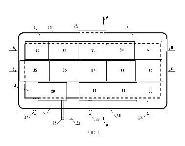
Fig. 1 shows the layout of the proposed complex on the GBS from the
top.
Fig. 2 ¨A-A transverse cross-section of Fig. 2.
Fig. 3 ¨ B-B longitudinal cross-section of Fig. 2.
Fig. 4 ¨ C-C longitudinal cross-section of Fig. 2.
Fig. 5 ¨ layout of the GBS main compartments.
Fig. 6 ¨ layout of topside modules supports on the GBS top slab.
Fig. 7 ¨ layout of the topside modules load-bearing structures.
Items in the drawings are numbered as follows:
1 ¨ GBS central part
2¨ GBS top slab
3¨ GBS protruding part
4¨ GBS base slab
5 ¨ GBS vertical wall
6 ¨ main compartments for LNG storage tanks
7 ¨ inner ballast compartments
8 ¨ outer ballast compartments
9 ¨topside support
CA 03238823 2024- 5- 22
6
¨ seabed reinforcement near the quay
11 ¨ GBS underbase foundation
12 ¨ LNG storage tank
13 ¨ support slab for LNG storage tank 12
5 14 ¨ vertical wall under support slab 13
¨ gas condensate storage tank (compartment)
16 ¨ auxiliary and engineering compartments
17 ¨ substandart gas condensate storage tank (compartment)
18 ¨ gasket
10 19 ¨ space between top slab 2 and topside modules 10
¨ internal ballast compartments under support slab 13
21 ¨ module column
22 ¨ module vertical bracing
23 ¨ module floor beam (girder)
15 24¨ topside main deck
¨ jetty for tankers
26 ¨ interconnecting piperack to shore
27 ¨ evacuation bridge
28 ¨ reception installation, condensate stabilization installation, and acid
gas
20 removal installation module
29 ¨ dehydration installation and mercury removal installation module
¨ wide fraction of light hydrocarbons (WFLH) extraction, fractionation
and liquefaction installations module
31 ¨ liquefaction installation module
25 32¨ mixed refrigerant compressor module (line A)
33 ¨ mixed refrigerant compressor module (line B)
34 ¨ boil-off gas, fuel gas system and heating medium compressors module
¨ 1st interconnecting module
36 ¨ 2nd interconnecting module
CA 03238823 2024- 5- 22
7
37 ¨ 3rd interconnecting module
38 ¨ 4th interconnecting module
39 ¨ power station module
40 ¨ main technical room and emergency diesel generators module
41 ¨ auxiliary systems module
42 ¨topside intermediate tier
43 ¨topside upper tier
44 ¨topside open tier
45 ¨ air cooled heat exchangers
46 ¨ piperacks on interconnecting modules
47 ¨ cable trays on interconnecting modules
48 ¨ local substations and control and measuring devices on interconnecting
modules
49 ¨ quayside
50 ¨ seabed of a water body
51 ¨ water level in the water body
EXAMPLES OF THE INVENTION IMPLEMENTATION
The liquefied natural gas (LNG) production complex on a gravity-
based structure (GBS) is a prefabricated technical product comprising a set of
process, utility and auxiliary equipment for production, storage and
offloading
of LNG and gas condensate.
The GBS LNG production complex is fabricated at a dedicated
industrial site and then towed afloat to its installation site. The GBS is
installed on a special underbase foundation on the seabed. To prevent
scouring of the bed under the GBS and the bed of the water body, gabions or
other similar devices may be placed on the bottom around the GBS. The GBS
is installed near a dedicated quay and is connected to the shore with
CA 03238823 2024- 5- 22
8
overpasses and bridges enabling installation of respective piping and cabling
without resorting to underwater pipelines and/or long above-water overpasses,
as well as ease of access to the production complex and swift personnel
evacuation. The short distance to the shore enables a simpler and cheaper
integration with onshore facilities, including the hydrocarbon field, from
which is a source of raw hydrocarbons for the production complex.
The main components making up the complex are the gravity-based
structure (GBS) and the topside ¨ modularized process equipment.
The topside of the LNG production complex comprises modules, on
which process and engineering equipment is mounted. Each module is an
individual complete three-dimensional structure with process equipment
and/or engineering equipment, piping, systems and networks intended to
accomplish one or more LNG process stages or to support the process.
Modules are delivered to their installation location on the GBS as
products with the required level of prefabrication. Modules installation onto
the GBS is followed by modules integration in terms of hook-up to other
modules and to GBS equipment installed beyond the topside.
Structurally, each topside module 28-41 is a three-dimensional steel
framework with bracings comprising several tiers, and inside the framework
equipment is installed. The module framework with bracings (Fig. 7)
primarily consists of vertical columns 21, vertical bracings 22, and floor
beams 23 with horizontal bracings.
For ease of equipment maintenance and personnel access, each module
has several tiers (decks). Each module is designed to have at least one
stairwell for personnel movement between the tiers, and evacuation. Main
tiers 24 of all modules are at the same height to combine evacuation routes
and load transporting routs across the topside, thus reducing the load on GBS
top slab 2. Other tiers 42-44 of the topside modules vary in height depending
CA 03238823 2024- 5- 22
9
on their function and equipment. Transition bridges can be installed between
tierss of adjacent modules.
Each module has its individual purpose as part of the LNG process and
has its individual set of equipment. Depending on the equipment they contain,
the modules can be equipment modules or interconnecting modules.
Equipment modules include:
= process modules (seven in this case), in which main LNG processes are
completed, and
= engineering modules (three in this case), in which power sources and
engineering systems are installed.
Interconnecting modules (four in this case) include piperacks and cable
trays, local substations and control and measuring devices, as well as air
cooled heat exchangers.
Process modules 28-34 are arranged as two rows on each side along
GBS top slab 2, interconnecting modules 35-38 are located between the two
rows along GBS top slab 2, and engineering modules 39-41 are concentrated
at one of GBS short ends (Fig. 1).
This arrangement enables rational equipment layout in consistency with
the LNG process sequence. The engineering modules are also separated from
the rest of the topside by fire-proof and explosion-proof walls, and there are
also fire-proof and explosion-proof walls between the process modules, which
enables the shortest distance between the modules and smaller dimensions of
the production complex while maintaining high level of fire and explosion
safety.
Process modules (Fig. 1 to 3):
1. Module 28 of reception installations, a condensate stabilization
installation, and an acid gas removal installation, in which raw gas
reception, pressure control, liquid condensate (hydrocarbons and water)
separation, carbon dioxide, hydrogen sulphide and methanol removal
CA 03238823 2024- 5- 22
10
from the raw gas, and gas condensate stabilization occur. Module 28 is
installed on the shoreward side of the GBS.
2. Module 29 of gas dehydration, mercury removal installations, in which
mercury, moisture and remaining methanol removal from the raw gas
occurs.
3. Module 30 of wide fraction of light hydrocarbons (WFLH) extraction,
fractionation installations, in which heavy hydrocarbon removal from
the gas before its supply to liquefaction occurs. The resulting liquid
hydrocarbons are stabilized and partially fractionated to obtain ethane,
propane, and butane fractions.
4. Module 31 of liquefaction installation, in which the gas is cooled and
throttled to produce liquefied natural gas (LNG).
Modules 29, 30 and 31 are located along the seaward side of the GBS.
5. Mixed refrigerant compressor module 32 (line A), in which three
different mixed refrigerants are treated and compressed using
centrifugal compressors driven by gas turbines. Waste heat of the gas
turbines flue gas can be recovered to heat up the heating media.
6. Mixed refrigerant compressor module 33 (line B), in which three
different mixed refrigerants are treated and compressed using
centrifugal compressors driven by gas turbines. Waste heat of the gas
turbines flue gas can be recovered to heat up the heating media.
Modules 32 and 33 are located on the shoreward side of the GBS.
7. Module 34 of boil-off gas, fuel gas system and heating medium
compressors, in which boil-off gas compression and distribution, fuel
gas treatment, heating media treatment and heating occur. Module 34 is
installed on the seaward side of the GBS.
Modules of engineering systems:
CA 03238823 2024- 5- 22
11
1. Power generation module 39, in which power is generated by gas
turbine generators. Waste heat of the gas turbines' flue gas can be
recovered to heat up the heating media.
2. Main technical room and emergency diesel generators module 40, in
which uninterrupted power sources and control and measuring devices
as well as air-cooled heat exchangers are located.
3. Module 41 of auxiliary systems, accommodating air supply and
nitrogen supply systems ¨ air compressors, air separation unit, air
dryer, and other equipment.
Modules 39, 40 and 41 are installed along a GBS short end.
The distribution of installations between the modules may vary. This is
a description of one of the options of filling modules with equipment.
Interconnecting modules 35, 36, 37, 38 lined up along the GBS top slab
have similar arrangement and set of equipment (Fig. 4):
= Main tier 24 accommodates local substations and control and
measuring devices 48,
= Intermediate tier 42 accommodates cable overpasses 47,
= Upper tier 43 accommodates pipeline overpasses 46,
= Open tier 44 accommodates air-cooled heat exchangers 45.
However, each interconnecting module 35, 36, 37, 38 has an individual
equipment composition depending on production processes occurring in
adjacent process modules. For instance, local substations and control and
measuting devices of module 48 support operation of equipment in process
modules on either side of each interconnecting module 35, 36, 37, 38, thus
enabling optimized switchgear layout and better equipment response time.
Having a significant part of cable and pipeline overpasses 46, 47 in
interconnecting modules 35, 36, 37, 38 enables optimized piping and cabling
interconnection between the modules, shorter cable runs and pipe runs, as
well as extra space for equipment in the process modules.
CA 03238823 2024- 5- 22
12
Air-cooled heat exchangers 45 on open tier 44 of interconnecting
modules 35, 36, 37, 38 are a part of process installations located in the
process modules. Interconnecting modules 35, 36, 37, 38 are located in the
topside central part along the GBS centerline and are higher than any of the
adjacent process modules, with air-cooled heat exchangers 45 installed on
open tier 44, which is the highest tier of interconnecting modules 35, 36, 37,
38. The installation of air-cooled heat exchangers 45 at the highest elevation
of topside enables the most efficient heat dissipation.
Module 40 of technical room and emergency diesel generators is also
located along the GBS centerline and is very tall, which is why it also
accommodates air-cooled heat exchangers 45.
The GBS is a three-dimensional structure made from reinforced
concrete, which functions as a storage for produced and processed feedstock,
as well as for auxiliary substances and materials. It serves as a foundation
for
the topside of the production complex and is designed to be installed on
seabed 50 of a water body with under its own weight. The central part 1 of the
GBS is shaped as a rectangular prism and has top slab 2 (Fig. 1).
On the sides of central part 1 along the whole perimeter, GBS
protruding part 3 with vertical outer walls is located. GBS central part 1 and
protruding part 3 share same base slab 4, and protruding part 3 is lower than
central part 1 (Figs. 2 and 3).
Central part 1 is broken down into compartments with vertical
longitudinal and transverse walls 5 (Figs. 2 to 5). Some of the compartments,
e. g. compartments 6 and 15, are used for product (LNG and condensate)
storage, while other compartments, e. g. compartments 7 and 20, are used for
ballast water. GBS protruding part 3 is broken down into compartments with
vertical walls 5 that are perpendicular to its external walls. Compartments 8
along the GBS perimeter are also included in the ballast system.
CA 03238823 2024- 5- 22
13
Top slab 2 has reinforced concrete supports 9, on which topside
modules 28 to 41 are mounted.
A GBS can stay afloat during water transportation to the site of the
integrated production complex and can withstand ice impact in ice conditions.
Changing the GBS condition from floating to stationary at the site of
installation on the foundation 11 is ensured by flooding the ballast
compartments 7, 8 and 20 with water.
Since reinforced-concrete walls 5 also serve as load-bearing structures
that transfer the load from the topside to support slab 13 and underbase
foundation 11, topside supports 9 are located above the intersections of
vertical longitudinal and transverse walls 5 of the GBS.
LNG, gas condensate, and consumables storage tanks are located inside
the GBS compartments. GBS central part 1 has a number of tanks that may
have different design depending on the properties of substances to be stored.
Membrane tanks are used for LNG storage. In this case, tank 12 comprising a
metal membrane made of stainless steel or invar (Fe-Ni alloy) separated from
concrete structure by an insulation layer is installed inside concrete
compartment 6 (Figs. 2, 4). The insulation layer is located directly on top
slab
2, intermediate slab 13 and GBS walls 5, transferring the loads from tank 12
and its LNG content to the above-mentioned boundary structures. The GBS
slabs and walls thus serve as support structures for membrane tanks, with
which they are integrated into a single structural unit. To prevent any leaks,
the bottom and the side surfaces of membrane tanks 12 have a secondary
barrier being an additional membrane installed inside the insulation layer.
LNG is stored in two 115,000-cbm tanks 12, each installed in a 135 x
40 x 24 m individual compartment 6.
Condensate may be stored in GBS concrete compartments 15 and 17,
with their boundary structures serving as a barrier. 135 x 30 x 30 m stable
condensate storage compartment 15 has a capacity of 75,000 cbm. 30 x 8 x 30
CA 03238823 2024- 5- 22
14
m compartment 17 is used for off-spec condensate storage and has a capacity
of 5,000 cbm.
"Wet" storage involving an underlying water layer is used for
condensate storage. In this case, the bottom layer of the stored product
around
1 m in thickness is considered a commingling area ensuring guaranteed
separation of water and the stored product during loading operations.
Compartments 15 and 17 is also slightly pressurized (from the atmospheric
pressure level) using a nitrogen cushion in the upper part of compartments to
air-proof compartments 15 and 17 and prevent any flammable and explosive
gas mixtures with hydrocarbon vapors from forming.
Self-supported tanks installed in the GBS compartments are used for
waste water, demineralized water, wash water, absorber, butane and propane.
Tanks for various media (liquefied gas, diesel fuel, propane, butane,
ethane, water) are located within the GBS as close as possible to the relevant
modules where such media are used, allowing to optimize the lengths and
masses of pipelines, electrical heat tracing, and insulation.
LNG and condensate offloading jetty 25 is structurally integrated with
the GBS and the topside. Fenders and an offloading platform with loading
arms as well as other marine and process equipment enabling LNG and
condensate offloading are installed on protruding part 3 on the GBS seaward
side. Mooring equipment for tanker berthing is installed on the GBS seaward
side. The water area near the jetty 25 may have seabed reinforcement 10
protecting the bottom soil from scouring by ships propellers.
The integrated production complex on a gravity-based structure is
connected to the shore by two overpasses 26 (Fig. 1 and 2) on which pipelines
and cable ways are laid. The pipelines connecting the production complex to
the field and other facilities are equipped with cut-off valves at the
overpasses
landfall. There are also three evacuation bridges 27 (Fig. 1) used for
personnel
movement and evacuation, if needed. The overpasses and bridges are made of
CA 03238823 2024- 5- 22
15
steel and mounted on supports. The supports are erected on GBS top slab 2 on
one end, and on quayside 49 on the other. Seabed 50 and water level 52 in the
body of water are shown on Figs. 2 to 4.
The process technology of the LNG production complex on GBS has
no fundamental differences from mixed refrigerant-based process
technologies, which are used at onshore plants. Raw gas and condensate from
the field are piped via overpass 26 to module 28 of reception installations,
in
which raw gas reception, pressure control, liquid condensate (hydrocarbons
and water) separation, carbon dioxide, hydrogen sulphide, methanol, and
other impurities removal from the raw gas, and gas condensate stabilization
occur. The process employs air-cooled heat exchangers installed on the open
tier of interconnecting module 35. The stabilized gas condensate is sent to
storage tanks 15 and 17 accommodated inside the GBS, while the treated raw
gas is sent to module 29 of gas dehydration and mercury removal where
mercury, moisture, and remaining methanol are removed from the raw gas
before it is sent to module 30 of wide fraction of light hydrocarbons (WFLH)
extraction, fractionation installations. The process employs air-cooled heat
exchangers installed on the open tier of interconnecting module 35. Module
30 of wide fraction of light hydrocarbons (WFLH) extraction, fractionation
installations is used to extract heavy hydrocarbons before the treated gas
transfer to liquefaction. The resulting liquid hydrocarbons are stabilized and
partially fractionated to obtain ethane, propane, and butane fractions for the
purposes of mixed refrigerant components replenishment. The GBS has
dedicated tanks to store these components. Stabilized heavy hydrocarbons are
sent to the gas condensate storage tanks. Once treated in modules 28-30, the
gas is sent to module 31 of liquefaction installation where three coil-wound
heat exchangers are installed one after another, which are used to cool the
gas
with subsequent throttling and generation of liquefied fraction (LNG) and
boil-off gas. The liquefied gas is sent to LNG storage tanks 12 accommodated
CA 03238823 2024- 5- 22
16
inside the GBS. Three mixed refrigerants with different composition (MR1,
MR2, MR3), which are mixtures of nitrogen, methane, ethane, propane, and
butane, are used for gas cooling in the heat exchangers. The process employs
air-cooled heat exchangers 45 installed on the open tiers of interconnecting
modules 36, 37, 38.
The mixed refrigerant treatment and compression occurs in mixed
refrigerant compressors modules 32 and 33. The refrigerant is air-cooled
downstream the compressor in air-cooled heat exchangers 45 in
interconnecting modules 36, 37 & 38, through which the refrigerant circulates
between module 31 of liquefaction installation and mixed refrigerant
compressors modules 32 and 33.
Each of the three mixed refrigerant loops has two parallel lines, A and
B, installed in different modules, with line A being installed in mixed
refrigerant compressors module 32 and line B being installed in mixed
refrigerant compressors module 33.
Both mixed refrigerant compressors modules 32 and 33 feature the
same compressor arrangement, with the compressors capacity being based on
a 2*50% operating mode, i. e. on 100% compressor backup. The MR1 and
MR2 compressors in each of module 32 and module 33 are on the same shaft
and the same baseframe, and are driven by the same gas turbine drive,
therefore reducing the number of gas turbine drives.
The refrigerant is produced from ethane, propane, and butane extracted
in module 30 of WFLH extraction, fractionation installations and stored in the
GBS tanks for replenishment purposes. Nitrogen for refrigerant production is
generated in module 41 of auxiliary systems. Methane replenishment is done
using treated raw gas and boil-off gas.
Boil-off gas generated in module 31 of liquefaction installation, LNG
storage tanks, and also in the gas carrier cargo tanks during offloading is
sent
to module 34 of boil-off gas, fuel gas system and heating medium
CA 03238823 2024- 5- 22
17
compressors for boil-off gas compression and distribution. Boil-off gas is
partially used for the treatment of fuel gas, which is primarily consumed by
gas turbines in power station module 39 and mixed refrigerant compressors
modules 32 and 33.
The gas turbines are equipped with waste heat recovery installations to
recover waste heat to be used to heat up the heating medium. Excessive heat
is evacuated from the heating medium system via air-cooled heat exchangers
45 mounted on the open tier of module 40 of main technical room and
emergency diesel generators. Since the modules accommodating the gas
turbines, the waste heat recovery installations, the fuel gas system and the
heating medium system are packed together, less piping is required and
efficient heat recovery is achieved.
The turbine drives of the mixed refrigerant compressors and the turbine
generators use unified gas turbines simplifying, and reducing the cost of,
equipment operation and maintenance.
CA 03238823 2024- 5- 22