Note: Descriptions are shown in the official language in which they were submitted.
WO 2023/087118 PCT/CA2022/051717
1
COMPOSITIONAL MULTISPECTRAL AND HYPERSPECTRAL IMAGING
SYSTEMS FOR MINING SHOVELS AND ASSOCIATED METHODS
CROSS-REFERENCE TO RELATED APPLICATIONS
[0001] The present application claims the benefit of U.S.
Provisional Patent Application
No. 63/282,087, filed November 22, 2021, which is incorporated herein by
reference in its entirety.
TECHNICAL FIELD
[0002] The present disclosure generally relates to mining
detection systems having imaging
systems and, in particular embodiments, to compositional multispectral and/or
hyperspectral imaging
systems positioned on mining equipment to classify ore and waste minerals at
the mining site and
associated methods and systems.
BACKGROUND
[0003] Mineral sorting is typically undertaken by one or more
sorting machines in a single stage
at a facility separate from the mining site that has sensor arrays controlling
a matched array of
diverters. Matched sensor/diverter arrays are typically positioned with
respect to an ore transport
mechanism (e.g., vibrating feeder, belt conveyor, free-fall type), which moves
the material to be
sorted past the sensors and through the diverters that sort the material into
separate streams (e.g., an
"accept" or "reject" stream).
[0004] Sorting machine capacity is limited by several factors,
including controller speed, belt
or feeder width, segregation of particle size ranges, and separation of
mineral composition (e.g.,
sulfide or oxide). The mineral composition dictates the extraction process
required to optimize ore
recovery. For example, sulfide ores are transported to flotation circuits,
while oxide ores are
transported to leaching circuits. Thus, if the sorting process inaccurately
diverts ore to the wrong
processing circuit based on mineral composition, the value of the ore is
diminished, which reduces
the efficiency of the circuit.
CA 03238874 2024- 5- 22
WO 2023/087118 PCT/CA2022/051717
2
BRIEF DESCRIPTION OF THE DRAWINGS
[0005] Many aspects of the present disclosure can be better
understood with reference to the
following drawings. The components in the drawings are not necessarily to
scale. Instead, emphasis
is placed on clearly illustrating the principles of the present disclosure.
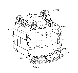
[0006] Figure 1 is a perspective view of a mining detection system
configured in accordance
with embodiments of the present technology.
[0007] Figure 2 is an enlarged perspective view of a compositional
multispectral imaging
system of the mining detection system of Figure 1 configured in accordance
with embodiments of the
present technology.
[0008] Figure 3 is a block diagram of a compositional
multispectral imaging system configured
in accordance with embodiments of the present technology.
[0009] Figure 4 is a diagram of a camera portion of the
compositional multispectral imaging
system of Figure 3.
[0010] Figure 5 is a diagram of a lighting portion of the
compositional multispectral imaging
system of Figure 3.
[0011] Figure 6 is a block diagram of a suitable computer that may
employ aspects of the
various embodiments of the present technology.
[0012] Figure 7 is a block diagram illustrating a suitable system
in which aspects of the various
embodiments described herein may operate in a networked computer environment.
DETAILED DESCRIPTION
[0013] Disclosed herein are various embodiments of compositional
imaging systems for
mining shovels including multispectral imaging (MSI) and/or hyperspectral
imaging (HSI) units,
methods of sorting material using a mining shovel with compositional MSI
and/or HSI units, and
systems incorporating compositional MSI and/or HSI units at a mining site. In
some embodiments
disclosed herein, the mining shovels include a bucket having an MSI system
with one or more
spectroscopy heads (also referred to as an "MSI head assembly" or "head
assembly"), each housing
an MSI camera unit, a lighting unit, and a sensor generally positioned near an
inlet of the bucket (e.g.,
CA 03238874 2024- 5- 22
WO 2023/087118 PCT/CA2022/051717
3
the opening of the bucket in which material enters the bucket cavity). The MSI
camera unit has a field
of view in which the MSI camera unit captures images of mining material prior
to, during, and/or
after loading the mining material into the bucket. The MSI camera unit can
include a lighting unit to
capture images of the mining material with or without flash. The lighting unit
can be spaced apart
from the MSI camera unit and illuminate an irradiation region, which at least
partially overlaps with
the field of view of the MSI camera unit. The sensor can detect
characteristics of the mining material
in the field of view. The MSI heads can be in communication with a control
component (e.g., one or
more controllers, also referred to as "processing units") mounted to the
bucket and/or remote from
the bucket and can receive and/or analyze the data collected by the MSI heads.
[0014] In some embodiments, one or more processing unit is used to
identify the mineral
composition of the ore and/or other mining material entering the bucket of the
mining shovel. In
some embodiments, the MSI heads can be positioned adjacent to one or more
sensors that detect
characteristics and/or properties of the bucket contents, e.g., including X-
Ray Fluorescence (XRF)
emitters, XRF detectors, laser distance sensors, ultrasonic distance sensors,
lidar distance sensors,
other multi-spectral imaging sensors, other flash tubes, hyperspectral imaging
cameras, hyperspectral
point spectrometers, stereoscopic cameras, radiation detectors,
electromagnetic detectors, gamma-ray
source sensors, and the like. The sensors can be positioned on a side wall of
the bucket, on an upper
wall portion of the bucket, adjacent to the MSI heads, between the MSI heads,
and/or at other suitable
sensor locations, and can be used in conjunction with the MSI heads to
identify the mineral
composition and improve the grade prediction of the ore and/or other mining
material entering the
bucket and/or positioned within the bucket. In some embodiments, any number of
MSI heads can be
used with any number of sensors. In some embodiments, the MSI heads described
herein can be used,
either in conjunction with the MSI heads positioned at the bucket or
independently, for sensing mining
material composition on a conveyor belt for carrying ore. Sorting the mineral
composition at the mine
face during digging reduces sorting operation costs by eliminating additional
sorting machines and
allowing an operator to make ore and/or other mining material routing
decisions at the mine face and
optimize the downstream extraction process.
[0015] The mining shovels with compositional MSI and/or HSI can be
part of a system used in
field operations (e.g., at a mining site) to direct where material located in
the bucket should be
CA 03238874 2024- 5- 22
WO 2023/087118 PCT/CA2022/051717
4
transported. In addition to the bucket described above, the system can include
additional signal
processing equipment located remote from the bucket, such as in the chassis of
the mining shovel,
and communications links between the signal processing equipment in the bucket
and the signal
processing equipment in the chassis. In this manner, data can be relayed from
the bucket to the
chassis, where, for example, further data analysis can be carried out. The
system can further include
an operator's enterprise resource planning (ERP) system, a fleet management
system, and/or
communications links for transmitting information between all of the
components of the system. In
some embodiments, predetermined values relating to identification of material
composition is stored
in a database that is part of the ERP system, such that data transmitted to
the ERP system from the
bucket and/or chassis can be compared against the database to match patterns
and thereby identify
material composition. Once material composition is identified, signals can be
sent from the ERP
system to the fleet management system so that a determination of where to
transport the material in
the bucket can be made. In other embodiments, the material composition
information is sent by the
signal processing equipment to the fleet management system. The decision made
by the fleet
management system can subsequently be communicated to, for example, a local
display located in
the chassis of the mining shovel so that a shovel operator can deposit the
bucket material in the
appropriate location.
[0016] In some embodiments, a method of in-mine sensing and
classification generally
includes collecting imaging data of material in a mining shovel bucket using
one or more MSI heads
carried by the bucket and transmitting the data obtained from sensing the
material to signal processing
equipment. The method can further include identifying the composition of the
material by processing
the data with image processing equipment. In some embodiments, the method can
further include
sensing, by the sensors, additional characteristics of the received material
to augment the material
composition identification by the data provided by the MSI heads and determine
further classification
of the composition of the material. Once identified, the method can further
include transmitting
instructions of where to transport the bucket material, such as to a mining
shovel operator.
Destination instructions can also be sent to a haul truck that receives the
material from the mining
shovel and/or to other operators in the mining ecosystem remote from the
mining shovel or mining
site.
CA 03238874 2024- 5- 22
WO 2023/087118 PCT/CA2022/051717
[0017] Specific details of several embodiments of the present
technology are described herein
with reference to Figures 1-7. The present technology, however, can be
practiced without some of
these specific details. In some instances, well-known structures and
techniques often associated with
mining detection systems, compositional MSI, and the like, have not been shown
in detail so as not
to obscure the present technology. Moreover, although many of the embodiments
are described below
with respect to systems and methods for identifying specific materials (e.g.,
sulfides and oxides)
and/or systems and methods mounted to a mining shovel bucket, other
applications and other
embodiments in addition to those described herein are within the scope of the
technology. Further,
although many of the embodiments are described below with respect to systems
and methods that use
compositional MSI, the systems and methods can utilize HSI and components
thereof (e.g.,
hyperspectral infrared point spectrometers) and/or color cameras (e.g., RGB
cameras) in place of or
in addition to the MSI components disclosed herein.
[0018] The terminology used in the description presented below is
intended to be interpreted
in its broadest reasonable manner, even though it is being used in conjunction
with a detailed
description of certain specific embodiments of the invention. Certain terms
may even be emphasized
below; however, any terminology intended to be interpreted in any restricted
manner will be overtly
and specifically defined as such in this Detailed Description section.
[0019] The accompanying Figures 1-7 depict embodiments of the
present technology and are
not intended to be limiting of its scope. The sizes of various depicted
elements are not necessarily
drawn to scale, and these various elements can be arbitrarily enlarged to
improve legibility.
Component details can be abstracted in the Figures to exclude details such as
position of components
and certain precise connections between such components when such details are
unnecessary for a
complete understanding of how to make and use the present technology. Many of
the details,
dimensions, angles, and other features shown in the Figures are merely
illustrative of particular
embodiments of the disclosure. Accordingly, other embodiments can have other
details, dimensions,
angles, and features without departing from the spirit or scope of the present
technology.
[0020] Figure 1 is a perspective view of a mining detection system
100a ("system 100a")
including a mining shovel bucket 110 (-bucket 110") carrying a compositional
MSI system 101
("MSI system 101") configured in accordance with embodiments of the present
technology. The
CA 03238874 2024- 5- 22
WO 2023/087118 PCT/CA2022/051717
6
bucket 110 can include a plurality of walls that form an open container having
an interior volume in
which mining material can be received and retained, and one or more sensors
positioned to detect
characteristics of material as it enters and/or when it is retained within the
interior volume of the
bucket 110. The MSI system 101 can include at least one MSI head assembly 130,
which includes
an MSI camera unit 132 and a lighting unit 134 positioned such that the MSI
camera unit 132 can
capture data from mining material entering or positioned within the cavity of
the bucket 110. The
bucket 110 can include a control enclosure 140, explained in greater detail
below, that is operably
coupled to components of the system 100a, for example, the sensors, the MSI
system 101, and/or
other electrical components.
[0021] In the illustrated embodiment, the bucket 110 includes a
first side wall 111a, a second
side wall 111b opposite the first side wall 111a, an upper wall 112a, a lower
wall 112b opposite the
upper wall 112a, and a back wall 113 that together create the interior volume
of the bucket 110. The
bucket 110 may generally be any type of bucket suitable for use in mining
shovel operations,
including buckets of varying shapes, sizes, and materials.
[0022] The MSI system 101 can be mounted on or integrated into a
portion of the bucket 110.
In the illustrated embodiment, for example, the MSI system 101 is positioned
on the upper wall 112a
of the bucket 110. While Figure 1 shows only one MSI head assembly 130
positioned on the upper
wall 112a, the mining shovel bucket 110 can include any number of MSI head
assemblies 130
positioned in various locations on the mining shovel bucket 110 (e.g.,
multiple MSI head assemblies
130 on the upper wall 112a (see Figure 2), on the first and second side walls
111a and 111b, in the
interior volume of the bucket 110, etc.), above the bucket (e.g., on a
structure mounted to a component
of the mining shovel) or in any other suitable location where the MSI system
101 can capture images
of the mining material prior to or during loading of the mining material into
the bucket. Further,
although each MSI head assembly 130 is shown with one MSI camera unit 132 and
one lighting unit
134, in some embodiments, the MSI head assembly 130 can include multiple MSI
camera units per
lighting unit, multiple lighting units per MSI camera unit, or multiple MSI
cameras and lighting units.
[0023] In some embodiments, the mining shovel bucket 110 can
further include one or more
sensors positioned to detect characteristics of material as it enters and/or
when it is retained within
the interior volume of the bucket 110. As shown in Figure 1, for example, the
system 100a can
CA 03238874 2024- 5- 22
WO 2023/087118 PCT/CA2022/051717
7
include in-chcek sensors 120 on the first side wall 111a and an in-cheek
sensor 122 on the second
side wall 111b, each in-cheek sensor 120 and 122 facing inward towards the
interior volume of the
bucket 110 so that material entering and positioned within the interior volume
can be subjected to
sensing by the in-cheek sensors 120 and 122. The bucket 110 can also or
alternatively include at least
one peripheral sensor 124 positioned along a periphery of an inlet 115 of the
bucket 110 on the upper
wall 112a and facing, e.g., downward (for a down looking peripheral sensor) at
the entrance to or into
the interior volume so that material being loaded into or within the interior
volume can be subjected
to sensing by the peripheral sensor 124, outward so that material on the
mining face can be subject to
sensing by the peripheral sensor 124, etc. The in-cheek sensors 120 and 122
and the peripheral sensor
124 can be any type of sensor suitable for use in analyzing and collecting
data on mining material
that can subsequently be used in determining the composition of the mining
material. For example,
the in-cheek sensors 120 and 122 and the peripheral sensor 124 can be
radiometric sensors,
photometric sensors, and/or electromagnetic sensors, e.g., the sensors shown
and described in U.S.
Patent Nos. 9,522,415, 10,036,142, and 10,982,414, each titled MINING SHOVEL
WITH
COMPOSITIONAL SENSORS, which are incorporated by reference herein in their
entirety. In some
embodiments, the system 100a can include a greater number of in-cheek sensors
and/or down looking
sensors than shown in Figure 1, and/or one or more of the in-cheek sensors
and/or down looking
sensors may be omitted. The sensors may be housed within and/or encapsulated
by a ruggedized,
non-metallic material such as one of vulcanized rubber or other rugged, non-
conductive elastomeric
material, that does not interfere with the operation of the sensor, yet
provides a robust housing to
protect the sensors from the rugged mining environment (e.g., hard, heavy
materials being scooped
within the bucket 110).
[0024] Figure 2 is a perspective view of a system 100b configured
in accordance with
embodiments of the present technology. In the illustrated embodiment, the
system 100b includes a
first MSI head assembly 130a having a first MSI camera unit 132a and an
associated a first lighting
unit 134a, and a second MSI head assembly 130b having a second MSI camera unit
132b and an
associated second lighting unit 134b. As shown in Figure 2, a first peripheral
sensor 124a can be
positioned between the first MSI camera unit 132a and the first lighting unit
134a, and a second
peripheral sensor 124b can be positioned between the second MSI camera unit
132b and the second
CA 03238874 2024- 5- 22
WO 2023/087118 PCT/CA2022/051717
8
lighting unit 134b. Embodiments with sensors positioned between the MSI head
components allow
the MSI camera and the sensor to gather data from the same portion of ore
and/or other mining
material entering or in the bucket 110 and correlate data for the same portion
of ore. Positioning the
down looking sensors between the MSI head components can allow a more dynamic
grade model
capable of compensating for changes in sulfide concentration. For example,
copper content contained
in sulfide materials (as opposed to oxide materials) may be underestimated
with data gathered only
by the down looking sensors, but using the sensor data in conjunction with the
imaging data from the
MSI heads 130a and 130b can compensate for changes in sulfide concentration.
In some
embodiments, an XRF sensor is used to determine the percent of copper in the
mining material. In
some embodiments, one or both of the peripheral sensors 124a and 124b can be
omitted, the system
101 can include additional sensors, and/or sensors can be spaced apart from
the MSI camera units
132a and 132b.
[0025] Each MSI camera unit 132 has a field of view 136
(identified individually as a first field
of view 136a and a second field of view 136b) and the associated lighting unit
134 has an irradiation
region 137 (identified individually as a first irradiation region 137a and a
second irradiation region
137b) directed such that at least a portion of the field of view 136 and the
irradiation region 137
overlap with each other such that the lighting unit 134 illuminates the region
in which the MSI camera
unit 132 takes image data to enhance image quality and/or allow for image
capture in dark
environments. In the embodiment illustrated in Figure 2, for example, the
first camera field of view
136a of the first MST camera unit 132a and the first irradiation region 137a
are directed toward each
other to a central region between the first MSI camera unit 132a and the first
lighting unit 134a, and
generally aligned with the data capture area of the first peripheral sensor
124a. Similarly, the second
camera field of view 136b of second MSI camera unit 132b and the second
irradiation region 137b
are directed toward a region between the second MSI camera unit 132b and the
second lighting unit
134b, and generally aligned with the data capture area the second peripheral
sensor 124b. In some
embodiments, for example, the field of view 136 of each MSI camera unit 132
and the corresponding
illumination region 137 can be directed downwardly, into the interior
compartment of the bucket 110,
and the peripheral sensor 124 can be a downward looking sensor directed to the
same or overlapping
region. In some embodiments, each MSI camera unit 132 and lighting unit 134
pair can be spaced
CA 03238874 2024- 5- 22
WO 2023/087118 PCT/CA2022/051717
9
apart from each other, rather than adjacent to each other, to provide for
specific lighting
characteristics, avoid the light from causing the direct capture of dust and
other debris during imaging
by the MSI camera unit 132, and/or allow a sensor to be positioned
therebetween. For example, the
MSI camera unit 132 and the lighting unit 134 can be spaced apart by 500mm to
800mm. In some
embodiments, the MSI camera unit 132 captures images without a flash. In some
embodiments, the
lighting unit is configured to emit a flash to provide a lighting environment
for consistent data
collection. In some embodiments, the lighting unit is configured to emit a
constant light source to
provide a consistent lighting environment for consistent data collection.
[0026] Referring to Figures 1 and 2 together, the systems 100a and
100b can further include
the control enclosure 140 (also referred to as a "control component") operably
coupled to components
of the MSI system 101, the sensors 120, 122, and 124, and/or other electrical
components that collect
data associated with the mined material as it enters the bucket 110 and/or
when it is retained within
the bucket 110. The control enclosure 140 can be mounted to a surface of the
bucket 110 (e.g., an
exterior surface outside of the bucket cavity) or remote from the bucket 110.
In the illustrated
embodiments, for example, the control enclosure can be mounted to a top
exterior surface of the upper
wall 112a. The size, shape, and material of the enclosure 140 is generally not
limited, and can be
selected such that it safely accommodates and protects the various electronics
that resides therein.
The control enclosure 140 can house or otherwise carry image processing
components, signal
processing components, communication components, memory components, and/or a
wide variety of
other or additional components used in carrying out partial or complete
processing of imaging data
and/or sensor data received from the MSI system 101 and/or the sensors 120,
122, and 124 and/or
transmit that data. For example, image and signal processing electronics of
the control enclosure 140
can receive image data and signals from the MSI system 101 and/or the sensors
120, 122, and 124,
and partially or fully process the image data and/or signals to identify the
composition of the mining
material loaded in the bucket 110. The communications components can then
transmit signals
including the processed data from the bucket 110 to locations remote to the
bucket 110 (e.g., to the
chassis of the mining shovel, haul trucks, mobile devices, remote stations on
the mining operation
field). In some embodiments, the communications components housed in the
enclosure 140 are
wireless communications components that wirelessly deliver signals to transmit
the processed data
CA 03238874 2024- 5- 22
WO 2023/087118 PCT/CA2022/051717
and/or associated information. In a situation where wireless communications
arc lost, the enclosure
140 can continue to operate independently and resume data communication when
the connection is
restored. The enclosure 140 can further house imaging, lighting, and/or sensor
electronics that are
part of the MSI camera units 132, the lighting units 134, and/or the sensors
120, 122, and 124. The
enclosure 140 can draw power from the mining shovel machine and/or include on-
board power
components (e.g., batteries, solar power) for powering the various MSI camera
units 132, lighting
units 134, sensors 120, 122, and 124, image and signal processing equipment,
communication
components, and the like. In some embodiments, the MSI system described herein
can be used, either
in conjunction with the MSI system positioned at the bucket or independently,
at a location different
from the bucket. For example, in some embodiments, the MSI system can be used
for sensing mining
material composition on a conveyor belt for carrying ore. In other
embodiments, the MSI system
described herein can be used for sensing mining material composition on an in-
pit hopper that helps
optimize the loading of hauling trucks.
[0027] Figure 3 is a block diagram showing additional details of
one of the MSI head
assemblies 130 of the MSI system 101 of Figures 1 and 2 configured in
accordance with embodiments
of the present technology. The MSI head assembly 130 includes the MSI camera
unit 132 and the
lighting unit 134. The MSI camera unit 132 can include a lens 131 to focus the
image on the sensor
of the MSI camera unit 132, and a band pass filter 133 positioned over the
lens 131 to provide the
proper spectral range for the MSI camera unit 132. The filter 133 and the lens
131 can be protected
by dirt and debris with a window 135. In some embodiments, the window 135 can
be a self-cleaning
window, e.g., the self-cleaning windows shown and described in U.S.
Provisional Patent Application
No. 63/281,929, filed November 22, 2021, and titled SELF-CLEANING SENSOR
WINDOW AND
ASSOCIATED SYSTEMS AND METHODS, which is appended hereto in Appendix A. The
head
assembly 130 can further include a hardware trigger 150 configured to actuate
the MSI camera unit
132 and the lighting unit 134 based on input from a proximity sensor 141
(e.g., a laser. see Figure 4)
that is configured to detect the distance between the MSI camera unit 132 and
the mining material.
Further, a central processing unit 160 can be in communication with the MSI
camera unit 132 and the
lighting unit 134 to provide a software trigger to actuate the MSI camera unit
132 and the lighting
unit 134, e.g., by an operator input, by instructions from the software, at a
set interval, etc. The central
CA 03238874 2024- 5- 22
WO 2023/087118 PCT/CA2022/051717
11
processing unit 160 can be in communication with the system of the mining
shovel 162 through a
cable reel, other communication line, and/or a wireless connection. The head
assembly 130 can
further include a power source 152 operably coupled to the various system
components (e.g., the
hardware trigger 150, the MSI camera unit 132, the lighting unit 134, and the
like) and configured to
provide power to these components. The components of the head assembly 130 can
be housed within
a single housing, spaced apart from each other in different housings (e.g.,
the control enclosure 140
of Figures 1 and 2), and/or separate components operably connected to each
other.
[0028] The lighting unit 134 can have varied light characteristics
(e.g., pulsed or continuous
beam, and varying spectra, illumination area, illumination intensity, and
illumination distribution),
and the lighting unit 134 can be triggered by the hardware trigger 150. The
lighting unit 134 can be
any suitable light source (e.g., xenon, halogen, incandescent, etc.), and the
light source types for the
lighting unit 134 may be specified based on expected durability when mounted
in an environment
such as the bucket 110. In some embodiments, the wavelengths of the light
emitted from the lighting
unit 134 can be predefined and configured to match and even extend beyond that
of the MSI camera
unit 132. In other embodiments, the wavelengths of light emitted from the
lighting unit 134 can be
predefined and configured to be of different wavelengths than that of the MSI
camera unit 132. Each
lighting unit 134 can include a lens and a reflector that enhance the
uniformity of the illumination
pattern (e.g., the illumination region 137 of Figure 2).
[0029] During mining operations, if the proximity sensor 141
detects mining material within
the depth of field (DOF) of the MSI camera unit 132 (e.g., between lm and 2m
of the MSI camera
unit 132), the hardware trigger 150 and/or the central processing unit 160 can
actuate the MSI camera
unit 132 to initiate the capturing of a series of images that can be used by
the image processing
equipment to analyze the mining material entering or contained within the
bucket 110. In some
embodiments, the MSI camera unit 132 can collect images using ambient light,
or can be used in
conjunction with light emitted by the lighting unit 134. Images captured using
ambient light can be
corrected in post image processing, which may eliminate the need for a
lighting unit in the MSI head
assembly 130. In some embodiments, a first image is taken by the MSI camera
unit 132 without light
from the lighting unit 134 and near the midrange of the DOF of the MSI camera
unit 132. Once the
first image is taken, the lighting unit 134 can sync with the MSI camera unit
132 to capture a
CA 03238874 2024- 5- 22
WO 2023/087118 PCT/CA2022/051717
12
subsequent image with illumination and also near the midrange of the DOF of
the MSI camera unit
132. Any order of image with ambient light or with illumination is also within
the scope of the present
technology. The image processing system can use the captured images to
estimate the material
composition and divide it into several categories, e.g., high oxide, low
oxide, oxide absent, etc. The
data from the image processing system can be used with the sensor data from
additional sensors (e.g.,
down-looking sensors) to further classify the mining material and increase
classification accuracy and
determine ore-waste distinctions, such as whether the ore and/or other mining
material should be
processed or discarded.
[0030] Figure 4 is a schematic illustration of camera components
of the MSI system 101 of
Figures 1 and 2. The camera components illustrated in Figure 4 can be housed
within a single
housing, spaced apart from each other in different housings (e.g., the control
enclosure 140 of Figures
1 and 2), and/or separate components operably connected to each other. As
shown in Figure 4, the
MSI camera unit 132 is in communication with an MSI camera board 180, which is
in communication
with a camera head input connector 190 (e.g., the image processing equipment
of the control
enclosure 140 of Figures 1 and 2) and a camera head output connector 192 to
the lighting unit 132
(see Figure 5). The MSI camera board 180 can include a super capacitor
assembly 182. The MSI
camera board 180 is in communication with a programmable logic controller
(PLC) 168 configured
to monitor the state of input devices and make decisions based upon software
to control the state of
output devices. The PLC 168 is in communication with an input/output (TO) link
master 166 that
provides a link for communication between various components of the schematic
of Figure 4. The
TO link master 166 is in communication with a camera temperature sensor 164
configured to
determine, for example, if the MSI camera unit 132 is below an operating
temperature range. If the
temperature is below an operating temperature range, the PLC 168 can send a
signal through the MSI
camera board 180 to a heater 178 configured to heat the MSI camera unit 132 to
within the operating
temperature range. The proximity sensor 141 can be used to determine if mining
material is within
the DOF of the MSI camera unit 132. The MSI system 101 may further include a
shutter 170 in
communication with the MSI camera board 180 and configured to protect the
window 135, the filter
133, and the lens 131 during use. The shutter 170 can be actuated by a
proximity sensor for opening
172 and a proximity sensor for closing 174.
CA 03238874 2024- 5- 22
WO 2023/087118 PCT/CA2022/051717
13
[0031] Figure 5 is a schematic illustration of lighting components
of the MSI system 101 of
Figures 1 and 2. The lighting components illustrated in Figure 5 can be housed
within a single
housing, spaced apart from each other in different housings (e.g., the control
enclosure 140 of Figures
1 and 2), and/or separate components operably connected to each other. As
shown in Figure 5, the
lighting unit 134 is in communication with an MSI flash board 202, which is in
communication with
a camera head input connector 194 from the camera head output connector 192.
In other
embodiments, the MSI flash board 202 is in communication with the system
(e.g., the image
processing equipment of the control enclosure 140 of Figures 1 and 2). The MSI
flash board 202 is
in communication with an analog input (AI) module 204 and with an TO module
206 that provides a
link for communication between various components of the schematic of Figure
5. The MSI flash
board 202 is in communication with a trigger board 210 having storage
capacitors 212, where the
trigger board 210 is configured to actuate the lighting unit 134. The MSI
system 101 may further
include a shutter 220 in communication with the TO module 204 and configured
to protect the lighting
unit 134 while not in use. The shutter 220 can be actuated by a proximity
sensor for opening 222 and
a proximity sensor for closing 224.
[0032] Figure 6 and the following discussion provide a brief,
general description of a suitable
computing environment in which aspects of the disclosed system can be
implemented. Although not
required, aspects and embodiments of the disclosed system will be described in
the general context
of computer-executable instructions, such as routines executed by a general-
purpose computer, e.g.,
a server or personal computer. Those skilled in the relevant art will
appreciate that the various
embodiments can be practiced with other computer system configurations,
including Internet
appliances, hand-held devices, wearable computers, cellular or mobile phones,
multi-processor
systems, microprocessor-based or programmable consumer electronics, set-top
boxes, network PCs,
mini-computers, mainframe computers and the like. The embodiments described
herein can be
embodied in a special purpose computer or data processor that is specifically
programmed, configured
or constructed to perform one or more of the computer-executable instructions
explained in detail
below. Indeed, the term -computer" (and like terms), as used generally herein,
refers to any of the
above devices, as well as any data processor or any device capable of
communicating with a network,
CA 03238874 2024- 5- 22
WO 2023/087118 PCT/CA2022/051717
14
including consumer electronic goods such as game devices, cameras, or other
electronic devices
having a processor and other components, e.g., network communication
circuitry.
[0033] The embodiments described herein can also be practiced in
distributed computing
environments, where tasks or modules are performed by remote processing
devices, which are linked
through a communications network, such as a Local Area Network ("LAN"), Wide
Area Network
("WAN-) or the Internet. In a distributed computing environment, program
modules or sub-routines
may be located in both local and remote memory storage devices. Aspects of the
system described
below may be stored or distributed on computer-readable media, including
magnetic and optically
readable and removable computer discs, stored as in chips (e.g., EEPROM or
flash memory chips).
Alternatively, aspects of the system disclosed herein may be distributed
electronically over the
Internet or over other networks (including wireless networks). Those skilled
in the relevant art will
recognize that portions of the embodiments described herein may reside on a
server computer, while
corresponding portions reside on a client computer. Data structures and
transmission of data
particular to aspects of the system described herein are also encompassed
within the scope of this
application.
[0034] Referring to Figure 6, one embodiment of the system
described herein employs a
computer 1000, such as a personal computer or workstation, having one or more
processors 1010
coupled to one or more user input devices 1020 and data storage devices 1040.
The computer is also
coupled to at least one output device such as a display device 1060 and one or
more optional additional
output devices 1080 (e.g., printer, plotter, speakers, tactile or olfactory
output devices, etc.). The
computer may be coupled to external computers, such as via an optional network
connection 1100, a
wireless transceiver 1120, or both.
[0035] The input devices 1020 may include a keyboard and/or a
pointing device such as a
mouse. Other input devices are possible such as a microphone, joystick, pen,
game pad, scanner,
digital camera, video camera, and the like. The data storage devices 1040 may
include any type of
computer-readable media that can store data accessible by the computer 1000,
such as magnetic hard
and floppy disk drives, optical disk drives, magnetic cassettes, tape drives,
flash memory cards, digital
video disks (DVDs), Bernoulli cartridges, RAMs, ROMs, smart cards, etc.
Indeed, any medium for
storing or transmitting computer-readable instructions and data may be
employed, including a
CA 03238874 2024- 5- 22
WO 2023/087118 PCT/CA2022/051717
connection port to or node on a network such as a local area network (LAN),
wide area network
(WAN) or the Internet (not shown in Figure 6).
[0036] Aspects of the system described herein may be practiced in
a variety of other computing
environments. For example, referring to Figure 7, a distributed computing
environment with a web
interface includes one or more user computers 2020 in a system 2000 are shown,
each of which
includes a browser program module 2040 that permits the computer to access and
exchange data with
the Internet 2060, including web sites within the World Wide Web portion of
the Internet. The user
computers may be substantially similar to the computer described above with
respect to Figure 6.
User computers may include other program modules such as an operating system,
one or more
application programs (e.g., word processing or spread sheet applications), and
the like. The computers
may be general-purpose devices that can be programmed to run various types of
applications, or they
may be single-purpose devices optimized or limited to a particular function or
class of functions.
More importantly, while shown with web browsers, any application program for
providing a graphical
user interface to users may be employed, as described in detail below; the use
of a web browser and
web interface are only used as a familiar example.
[0037] At least one server computer 2080, coupled to the Internet
or World Wide Web ("Web")
2060, performs much or all of the functions for receiving, routing and storing
of electronic messages,
such as web pages, audio signals, and electronic images. While the Internet is
shown, a private
network, such as an intranet may indeed be preferred in some applications. The
network may have a
client-server architecture, in which a computer is dedicated to serving other
client computers, or it
may have other architectures such as a peer-to-peer, in which one or more
computers serve
simultaneously as servers and clients. A database 2100 or databases, coupled
to the server
computer(s), stores much of the web pages and content exchanged between the
user computers. The
server computer(s), including the database(s), may employ security measures to
inhibit malicious
attacks on the system, and to preserve integrity of the messages and data
stored therein (e.g., firewall
systems, secure socket layers (SSL), password protection schemes, encryption,
and the like).
[0038] The server computer 2080 may include a server engine 2120,
a web page management
component 2140, a content management component 2160 and a database management
component
2180. The server engine performs basic processing and operating system level
tasks. The web page
CA 03238874 2024- 5- 22
WO 2023/087118 PCT/CA2022/051717
16
management component handles creation and display or routing of web pages.
Users may access the
server computer by means of a URL associated therewith. The content management
component
handles most of the functions in the embodiments described herein. The
database management
component includes storage and retrieval tasks with respect to the database,
queries to the database,
and storage of data.
Further Examples
[0039] The following examples are illustrative of several
embodiments of the present
technology:
1. A mining detection system for mining shovels, the mining detection
system
comprising:
a head assembly configured to be positioned at an inlet portion of a mining
shovel bucket, the
head assembly comprising¨
a camera unit comprising a multispectral imaging (MSI) camera unit and/or a
hyperspectral imaging (HSI) camera unit, wherein the camera unit has a field
of view and is configured to capture images of mining material prior to,
during,
and/or after loading the mining material into the mining shovel bucket;
a lighting unit spaced apart from the camera unit and configured to illuminate
an
irradiation region, wherein at least a portion of the irradiation region
overlaps
with at least a portion of the field of view; and
a sensor configured to detect characteristics of the mining material in the
field of view;
and
a control component comprising a processing unit operably coupled to the head
assembly.
2. The mining detection system of any one of the examples herein wherein
the camera
unit is a first camera unit, wherein the first camera unit is a compositional
multispectral imaging
(MSI) camera unit, and the head assembly further comprises a second camera
unit, wherein the second
camera unit is a compositional hyperspectral imaging (HSI) camera unit.
CA 03238874 2024- 5- 22
WO 2023/087118 PCT/CA2022/051717
17
3. The mining detection system of any one of thc examples herein wherein
the camera
unit comprises a lens and a band pass filter positioned over the lens, and
wherein the head assembly
further comprises a window configured to protect the camera unit.
4. The mining detection system of any one of the examples herein wherein
the lighting
unit is configured to emit light having a predefined wavelength range
corresponding to a camera
wavelength range detectable by the camera unit.
5. The mining detection system of any one of the examples herein wherein
the lighting
unit is configured to emit light having a predefined wavelength range
different from a camera
wavelength range detectable by the camera unit.
6. The mining detection system of any one of the examples herein wherein
the camera
unit and the lighting unit are downward looking such that the field of view
and the irradiation region
are configured to be directed into the mining shovel bucket.
7. The mining detection system of any one of the examples herein wherein
the processing
unit is configured to determine a material composition of the mining material
based on the images
captured by the imaging system.
8. The mining detection system of any one of the examples herein wherein
the sensor is
an in-cheek sensor configured to be positioned on a side wall portion of the
mining shovel bucket.
9. The mining detection system of any one of the examples herein wherein
the sensor is
positioned between the camera unit and the lighting unit.
10. The mining detection system of any one of the examples herein wherein
the sensor is
a proximity sensor configured to determine whether the mining material is
within a depth of field
(DOE) of the camera unit, and wherein the mining detection system further
comprises a shutter
CA 03238874 2024- 5- 22
WO 2023/087118 PCT/CA2022/051717
18
positioncd to protect a lens of the camera unit, the shutter being operably
coupled to the proximity
sensor such that the proximity sensor is configured to actuate the shutter
when the mining material is
within the DOF.
11. The mining detection system of any one of the examples herein wherein
the sensor is
a radiometric sensor, a photometric sensor, and/or an electromagnetic sensor.
12. The mining detection system of any one of the examples herein wherein
the control
component is configured to, based on the images from the camera unit, classify
the mining material
in one of the following categories: high oxide, low oxide, or oxide-absent.
13. The mining detection system of any one of the examples herein wherein
the sensor is
an x-ray fluorescence sensor configured to determine a percent of copper in
the mining material.
14. The mining detection system of any one of the examples herein wherein
the head
assembly is housed within a ruggedized and/or non-metallic material configured
to not interfere with
operation of the sensor.
15. A mining detection system for mining shovels, the mining detection
system
comprising:
a head assembly configured to be positioned at an inlet portion of a mining
shovel bucket, the
head assembly comprising¨
a camera unit comprising a multispectral imaging (MSI) camera unit and/or a
hyperspectral imaging (HSI) camera unit, wherein the camera unit has a field
of view and is configured to capture images of mining material prior to,
during,
and/or after loading the mining material into the milling shovel bucket; and
a lighting unit spaced apart from the camera unit and configured to illuminate
an
irradiation region, wherein at least a portion of the irradiation region
overlaps
with at least a portion of the field of view; and
a control component comprising a processing unit operably coupled to the head
assembly.
CA 03238874 2024- 5- 22
WO 2023/087118 PCT/CA2022/051717
19
16. The mining detection system of any one of the examples herein, further
comprising a
mining shovel bucket, wherein the head assembly is positioned at an inlet
portion, an upper wall
portion of, at an interior side wall portion of, or above the mining shovel
bucket.
17. The mining detection system of example 16 wherein the control component
is
positioned at an exterior upper wall portion of the mining shovel bucket.
18. The mining detection system of any one of the examples herein further
comprising a
sensor configured to detect characteristics of the mining material in the
field of view.
19. The mining detection system of example 18 wherein the sensor is an in-
cheek sensor
positioned on a first side wall portion, a second side wall portion, or an
upper wall portion of the
mining shovel bucket.
20. The mining detection system of example 18 wherein the sensor is a
peripheral sensor
positioned on an inlet portion of the mining shovel bucket and between the
camera unit and the
lighting unit.
21. A method of classifying and sorting mining material at a mine site, the
method
comprising:
receiving the mining material in an interior region of a mining shovel bucket;
capturing images of the mining material entering or within the interior region
using a camera
unit positioned at an inlet portion of the mining shovel bucket, wherein the
camera
unit comprises a compositional multispectral imaging (MS I) camera unit and/or
a
compositional hyperspectral imaging (HSI) camera unit; and
processing, via a control component operably coupled to the camera unit, the
images captured
by the camera unit to identify compositional properties of the mining
material.
CA 03238874 2024- 5- 22
WO 2023/087118 PCT/CA2022/051717
22. The method of any one of the examples herein, furthcr comprising
illuminating at least
a portion of a field of view of the camera unit while the camera unit is
capturing images of the mining
material.
23. The method of any one of the examples herein, further comprising:
determining, via a proximity sensor, whether the mining material is within a
depth of field
(DOF) of the camera unit; and
initiating the capture of images via the camera unit when in the DOF.
24. The method of any one of the examples herein, further comprising
determining, via an
x-ray fluorescence sensor, a percent of copper in the mining material.
25. The method of any one of the examples herein wherein the images are
captured by the
camera unit with a flash.
26. The method of any one of the examples herein wherein the images are
captured by the
camera unit without a flash.
27. The method of any one of the examples herein further comprising
classifying the
mining material, based on the images captured by the camera unit, in one of
the following categories:
high oxide, low oxide, or oxide-absent.
28. The method of example 27 further comprising sorting the mining material
based on the
categories.
Conclusion
[0040] In general, the detailed description of embodiments of the
present technology is not
intended to be exhaustive or to limit the invention to the precise form
disclosed above. While specific
embodiments of, and examples for, the present technology are described above
for illustrative
purposes, various equivalent modifications are possible within the scope of
the present technology,
CA 03238874 2024- 5- 22
WO 2023/087118 PCT/CA2022/051717
21
as those skilled in the relevant art will recognize. For example, while
processes or blocks are
presented in a given order, alternative embodiments may perform routines
having steps, or employ
systems having blocks, in a different order, and some processes or blocks may
be deleted, moved,
added, subdivided, combined, and/or modified. Each of these processes or
blocks may be
implemented in a variety of different ways. Also, while processes or blocks
are at times shown as
being performed in series, these processes or blocks may instead be performed
in parallel, or may be
performed at different times.
[0041] Aspects of the present technology may be stored or
distributed on computer-readable
media, including magnetically or optically readable computer discs, hard-wired
or preprogrammed
chips (e.g., EEPROM semiconductor chips), nanotechnology memory, biological
memory, or other
data storage media. Alternatively, computer implemented instructions, data
structures, screen
displays, and other data under aspects of the present technology may be
distributed over the Internet
or over other networks (including wireless networks), on a propagated signal
on a propagation
medium (e.g., an electromagnetic wave(s), a sound wave, etc.) over a period of
time, or they may be
provided on any analog or digital network (packet switched, circuit switched,
or other scheme). Those
skilled in the relevant art will recognize that portions of the present
technology reside on a server
computer, while corresponding portions reside on a client computer such as a
mobile or portable
device, and thus, while certain hardware platforms are described herein,
aspects of the present
technology are equally applicable to nodes on a network.
[0042] The teachings of the present technology provided herein can
be applied to other systems,
not necessarily the system described herein. The elements and acts of the
various embodiments
described herein can be combined to provide further embodiments.
[0043] Any patents, applications and other references, including
any that may be listed in
accompanying filing papers, are incorporated herein by reference. Aspects of
the present technology
can be modified, if necessary, to employ the systems, functions, and concepts
of the various references
described above to provide yet further embodiments of the present technology.
[0044] These and other changes can be made to the present
technology in light of the above
Detailed Description. While the above description details certain embodiments
of the present
technology and describes the best mode contemplated, no matter how detailed
the above appears in
CA 03238874 2024- 5- 22
WO 2023/087118 PCT/CA2022/051717
22
text, the present technology can be practiced in many ways. Details of the
present technology may
vary considerably in its implementation details, while still being encompassed
by the present
technology disclosed herein. As noted above, particular terminology used when
describing certain
features or aspects of the present technology should not be taken to imply
that the terminology is
being redefined herein to be restricted to any specific characteristics,
features, or aspects of the present
technology with which that terminology is associated. In general, the terms
used in the following
claims should not be construed to limit the present technology to the specific
embodiments disclosed
in the specification, unless the above Detailed Description section explicitly
defines such terms.
Accordingly, the actual scope of the invention encompasses not only the
disclosed embodiments, but
also all equivalent ways of practicing or implementing the present technology.
CA 03238874 2024- 5- 22