Note: Descriptions are shown in the official language in which they were submitted.
WO 2023/102218
PCT/US2022/051704
CARTRIDGE PACKAGING SYSTEMS AND METHODS
CROSS REFERENCE TO RELATED APPLICATIONS
This application claims priority to U.S. Provisional Patent Application No.
63/285,323 entitled "CARTRIDGE PACKAGING SYSTEMS AND METHODS,-
filed December 2, 2021 (the '323 Provisional Application). The entire
disclosure of the
'323 Provisional Application is hereby incorporated herein.
TECHNICAL FIELD
Electronic smoking consumption, or "vaping," is an activity that has seen a
recent increase in popularity. There is currently a large variety of vaping
devices and
liquids available on the market. One way in which vaping liquids are consumed
is by a
user inhaling a vaporized aerosol from a cartridge. This vaporized solution
may be
generated by heating a liquid solution stored in the cartridge. Aspects of the
invention
include an apparatus and method that increases the efficiency of packaging
multiple
vaping liquid cartridges at one time.
BRIEF SUMMARY OF THE INVENTION
In one aspect, a vaping liquid packaging system is comprised of: a first tray
formed of deformable material for holding vaping device bodies, the first tray
having a
plurality of voids, each of the voids holding a portion of a vaping device
body to be filled
with a substance, and wherein the first tray and the vaping device bodies are
covered by a
first cover; a second tray formed of deformable material for holding vaping
device
mouthpieces, the second tray having a plurality of voids allowing the vaping
device
mouthpieces to be vertically aligned with the vaping device bodies of the
first tray, each
of the voids holding a portion of a vaping device mouthpiece to cap a
corresponding
vaping device body; wherein the first tray is capable of being placed over a
jig having a
plurality of jig voids corresponding to the voids for holding the vaping
device bodies, and
wherein the jig voids comprise a stepped portion within the jig voids, the
stepped portion
forming a concentric circle with the jig voids; and wherein the second tray is
capable of
being placed over the first tray to allow a press to exert even pressure on
the vaping
device mouthpieces of the second tray to press-fit the vaping device
mouthpieces onto the
corresponding vaping device bodies, the stepped portion of the jig void for
transferring
pressure from the vaping device mouthpieces to a corresponding bottom side of
a tank
1
CA 03239705 2024- 5- 30
WO 2023/102218
PCT/US2022/051704
portion of the vaping device bodies when the press exerts even pressure on the
vaping
device mouthpieces.
According to another aspect, a vaping device packaging system comprises: a
first
tray for holding vaping device bodies, the first tray having a plurality of
voids, the voids
holding a portion of a vaping device body to be filled with a substance, and
wherein the
first tray and the vaping device bodies are covered by a first cover; a second
tray for
holding vaping device mouthpieces, the second tray having a plurality of voids
allowing
the vaping device mouthpieces to be vertically aligned with the vaping device
bodies of
the first tray, each of the voids holding a portion of a vaping device
mouthpiece to cap a
corresponding vaping device body; and wherein the first tray is capable of
being placed
over a jig having a plurality of jig voids corresponding to the voids for
holding the vaping
device bodies.
According to another aspect, a method is provided for packing vaping devices.
A
method of packaging vaping devices can comprise: selecting a first tray for
holding
vaping device bodies, the first tray having a plurality of voids, inserting a
portion of a
vaping device body into each of the plurality of voids of the first tray;
covering the first
tray and the vaping device bodies with a first cover; selecting a second tray
for holding
vaping device mouthpieces, the second tray having a plurality of voids;
inserting a portion
of a vaping device mouthpiece into each of the plurality of voids in the
second tray.
BRIEF DESCRIPTION OF THE DRAWINGS
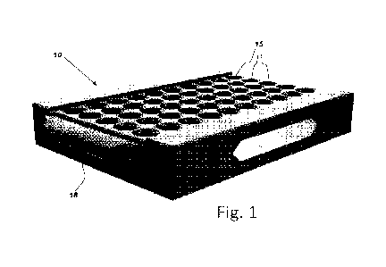
FIG. 1 provides a pictorial representation of a jig or receiver tray according
to one
embodiment.
FIG. 2 provides an up-close view of jig voids in a jig.
FIG. 3 shows a first tray loaded with vaping device bodies for placement over
a
jig.
FIG. 4. shows the first tray and jig of FIG. 3 with the vaping device bodies
of the
first tray loaded into the jig voids of the jig.
FIG. 5 is a partial cross-sectional view of an embodiment of a jig having a
jig void
with a vaping device body of a first tray located or seated within the jig
void.
FIG. 6 is a perspective view of an embodiment of an alignment plate.
FIG. 7 is a perspective view of an alignment plate being placed over vaping
device bodies of a first tray.
FIG. 8 is a perspective view of the alignment plate of FIG. 7 in place over
vaping
2
CA 03239705 2024- 5- 30
WO 2023/102218
PCT/US2022/051704
device bodies of a first tray.
FIG. 9 is a perspective view of vaping device bodies being filled by a
robotized
filling machine.
FIG. 10 is a perspective view of a vaping device body.
FIG. 11 is a perspective view of a second tray holding vaping device
mouthpieces
in place in vertical alignment with the first tray to cap the mouthpieces of
the second tray
onto the corresponding vaping device mouthpieces of the second tray.
FIG. 12 is a perspective view of a set of capped vaping devices in a jig.
DETAILED DESCRIPTION
With reference to FIGs. 1-4, a receiver tray or jig 10 may be designed as a
rectangular (cubic) structure with orifices, openings, voids, or holes. In
some
embodiments, each hole or jig void 15 may be a cylindrical cavity with an axis
that is
substantially perpendicular to a horizontal ground plane when the receiver
tray is placed
flat on a plane parallel to the horizontal ground plane. Each hole may be
internally
contoured for convenient insertion and removal of a vaping cartridge or a
vaping device
body as discussed in more detail below. In other embodiments, the holes have
different
shapes and sizes to accommodate vaping device bodies of different shapes and
sizes.
A receiver tray or jig 10 may have several holes, or a plurality of jig voids
15, with each hole being configured to hold a single cartridge. A jig 10 or
receiver
tray can be any shape or size and includes rectangular trays, square trays, or
any
other structure to hold one or more vaping device bodies and guide the vaping
device bodies as they are filled and capped. The jig voids 15 in a receiver
tray or jig
10 may be spaced at substantially regular intervals in some embodiments. For
example, Figure 1 depicts an embodiment of a jig 10 with a plurality of jig
voids
15, formed as a 10 x 5 matrix (array) of jig voids 15, with the receiver tray
or jig 10
in Figure 1 being configured to hold a total of 50 cartridges or vaping device
bodies. Other numbers of cartridges and/or configurations for jig voids 15 are
possible. The receiver tray or jig 10 may have handles 18 at two of its
opposite
edges to facilitate holding and transportation. In other embodiments handles
are not
provided. Figure 2 depicts a close-up of the receiver tray or jig 10 and the
structure
of the holes.
In one aspect, each hole or jig void 15 is designed to have a circular cross-
sectional profile with varying diameters. In other embodiments, the jig voids
15 have
3
CA 03239705 2024- 5- 30
WO 2023/102218
PCT/US2022/051704
other cross-sectional shapes to hold or partially hold vaping cartridges or
all-in-one
vaping systems that have varying shapes and sizes. Referring to FIG. 2, the
top of a
hole or jig void 15 may have a shape of a frustum of a cone, tapering in a
downward
direction. In other words, the top of the jig void maybe chamfered or have a
chamfered
edge 24. This physical profile serves to appropriately guide and align a
cartridge or
vaping device body being placed into the hole. The frustum section narrows in
a
downward direction, converging to a first cylindrical section 28 with a first
diameter,
and then to a second cylindrical section 32 with a second diameter (best seen
in FIG. 5).
In one aspect, the frustum, the first cylindrical section, and the second
cylindrical
section may all be substantially coaxial or concentric. Between the first
section 28 and
the second section 32 is a stepped portion 20.
The first diameter of the first section 28 may be substantially equal to a
diameter
of the narrow end of the frustum. The second diameter of the second section 32
may be
smaller than the first diameter. The portion of the hole where the first
diameter
transitions to the second diameter may be designed to be a flat, circular edge
surface or
a stepped portion 20 of the jig void 15. This contoured cross- sectional
profile of each
hole enables a cartridge to be guided in (by the frustum section 24) and then
securely
held (by a combination of the first section 28 and second section 32), thereby
minimizing any chances of misalignment due to user error and other errors.
This
contoured profile also minimizes any chances of damaging a cartridge.
The stepped portion 20 of the jig 10 may have a diameter that is from about
0,5
mm to about 1 mm, or from about 0.6 mm to about 0.9 mm, or from about 0.7 mm
to
about 0.8 mm. We have learned that during the capping process, it may damage
the
bottom side of a vaping device body if the capping pressure from the press is
transferred from a press to the bottom side 57 of the vaping device body 50.
If a stepped
portion 20 is provided within the jig void 15, within a special range, the
stepped portion
20 can transfer the capping pressure from the press to the bottom side 52 of
the vaping
device body tank portion 55, rather than the bottom side 57 of the vaping
device body.
This can reduce damage to the bottom side of the vaping device body during
capping.
As best seen in FIG. 5, downward pressure on the vaping device body 50 is
transferred
from the bottom side 52 of the tank portion 55 to the stepped portion 20 of
the jig voids
15.
The receiver tray or jig 10 may be configured to hold multiple cartridges or
vaping device bodies 50 so the vaping device bodies may be filled with vaping
4
CA 03239705 2024- 5- 30
WO 2023/102218
PCT/US2022/051704
solution (also referred to as "vape juice" or "oil(s)") or other substance.
The vaping
device bodies may be filled manually, or automatically via a robotic machine.
In one aspect, the vaping device bodies may be loaded into the receiver tray
or
jig 10 individually. In another aspect, the vaping device bodies 50 may be
preloaded into
a first tray 40 (a vaping device body tray) and then placed in the jig 10 or
receiver tray.
The first tray 40 is for holding vaping device bodies, or at least a portion
of a vaping
device body. The first tray 40 may define holes or a plurality of voids 44
that physically
and spatially match the hole arrangement on the jig 10 or receiver tray. That
is, each of
the vaping device bodies 50 in the first tray 40 may correspond to a jig void
15.
The first tray may 40 be formed of any suitable material and in some
configurations the material is a deformable material, such as a foam, etc., to
provide
cushioning for the vaping device bodies during transportation, filling, and
capping. The
plurality of voids 44 in the first tray 40 may be sized and shaped receive a
portion of a
vaping device body, or a portion of a cartridge body. A pictorial
representation of a
complete set of vaping device bodies 50 being loaded or placed over a jig 10
using a
first tray 40 is shown in Figure 3. Figure 4 depicts the full set of vaping
device bodies 50
as fully loaded into the jig 10 using the first tray 40 for holding vaping
device bodies 50.
The first tray 40 may be loaded or filled with vaping device bodies 50 such
that
the bottom portion of the vaping device body (for being placed into the jig
voids 15 of
the jig 10) extend below the first tray 40, and the top portion of the vaping
device body
(for haying mouthpieces capped over) extend above the first tray 40.
The first tray 40, along with the vaping device bodies 50 loaded into the
first
tray, can be provided with a first cover. In some embodiments, the first cover
may be a
sealed cover to protect the vaping device bodies from any dust, etc., during
transport.
For example, a sealed plastic cover may surround the first tray 40 and the
vaping device
bodies 50 loaded into the first tray 40. This may also simplify packaging to
facilitate the
filling and capping process.
Once the jig 10 has been fully loaded with the vaping device bodies of the
first
tray 40, an option step is to place an alignment plate 59 or stabilizer plate
on top of the
vaping device bodies. In one aspect, the stabilizer or alignment plate 59 is a
rigid plate
(e.g., a plastic or metal plate) that may be configured with holes that
physically and
spatially match the hole arrangement on the receiver tray. Each hole on the
stabilizer
tray may be diametrically matched with the diameter of a cartridge. Each hole
on the
stabilizer plate may also physically grasp (i.e., fasten on to) an area
towards the top end
5
CA 03239705 2024- 5- 30
WO 2023/102218
PCT/US2022/051704
of each cartridge and hold the cartridge in place. The stabilizer plate
ensures that each
cartridge is substantially immobile with respect to each other cartridge and
the receiver
tray. In combination, the stabilizer plate and the receiver tray provide a
rigid support for
an array of cartridges to be processed (i.e., filled and capped). Figure 6
shows a picture
of an embodiment of a stabilizer plate or alignment plate 59. Figure 7 shows
stabilizer/alignment plate 59 being placed over a first tray 40 filled with
vaping device
bodies 50. Figure 8 depicts the stabilizer/alignment plate 59 installed in
place over a
first tray 40.
Once the alignment plate 59 has been installed, the vaping device bodies 50
may be filled. The filling process may be accomplished manually or
automatically
(e.g., by using a robotized filling machine). Figure 9 depicts an array of
cartridges
being filled by a robotized filling machine. (For clarity, the figures do not
depict the
stabilizer/alignment plate 59.) In some embodiments, the robotized filling
machine
dispenses vaping liquid via a needle.
Each vaping device body 50 or cartridge may be designed to be consistent with
the filling process. For example, a cartridge may have an annular cylindrical
cavity that
accepts the vaping solution. For this process, the needle of a robotized
filling machine
may be inserted into the annular cylindrical cavity, as shown in Figure 9.
Figure 10 depicts an image of a vaping device body 50 or cartridge. The
proximal end 51 of the vaping device body 50 can have a mouthpiece attached. A
central lumen 53 extends past the edge of the tank portion 55 of the vaping
device body,
and can include a projection for a mouthpiece to interface or one-way lock
fit. The tank
portion 55 of the vaping device body is open on the proximal end to allow the
tank
portion 55 to be filled with vaping liquid or other substance. A cap
(mouthpiece) may be
placed over the proximal end 51 during the packaging process.
The bottom side 57 of the vaping device body is placed facing downwards in the
jig voids 15 of the jig 10. The threaded portion of the bottom end 57 may be
used to
interface (i.e., screw into) a power source, battery, etc. The tank portion 55
can also
have a metal band surrounding the bottom of the tank portion, or a cylindrical
metallic
portion of the cartridge at the lower end of the cartridge. This band or
metallic portion is
configured to be wider than the threaded portion of the bottom end of the
cartridge. That
is, the tank portion 55 of the vaping device body 50 is wider than the
threaded bottom
portion of the vaping device body 50.
6
CA 03239705 2024- 5- 30
WO 2023/102218
PCT/US2022/051704
In one aspect, the bottom of the tank portion of the v aping device body is
used to
bear a force associated with a capping process, to prevent any damage to the
threaded
portion of the cartridge or bottom side of the vaping device body. In one
aspect, when a
vaping device body is inserted into a jig void 15 in the jig 10, the bottom
side of the
tank portion of the vaping device body rests on the stepped portion 20 of the
jig void 15.
In other words, the bottom side of the tank portion rest on the surface where
the first
portion 28 of the jig void 15 transitions to the second portion 32 of the jig
void 15.
During a capping process when a vertical force is exerted on a cap to affix
the vaping
device mouthpiece onto the vaping device body, the force is transmitted to
bottom side
of the tank portion 55 that rests on the stepped portion 20 or circular edge
surface, rather
than on the threaded portion (which would be the case if the stepped portion
20 or
circular edge surface was not present). We have found that the bottom side 52
of the
tank portion 55 of the vaping device body 50 is better being able to bear the
force of the
capping process, and that this reduces damage to the threaded portion of the
cartridge.
After the vaping device bodies have been filled, the next stage is to install
a
cap (vaping device mouthpiece) on each vaping device body. FIG. 11 shows a
second tray 80 for holding vaping device mouthpieces 85. The second tray has a
plurality of voids allowing the vaping device mouthpieces to be vertically
aligned
with the vaping device bodies 50 of the first tray 40. Each of the voids holds
a
portion of a vaping device mouthpiece. That is, the portion of the vaping
device
mouthpiece to be inserted onto the proximal end of the vaping device bodies
extends
below the second tray 80. In one aspect, the mouthpieces may be collectively
placed
in a second tray 80 with holes that correspond in geometry and position to the
first
tray 40.
In one aspect, a mechanical press may be used to fasten each vaping device
mouthpiece onto a corresponding vaping device body. The second tray 80 is
capable of
being placed over the first tray 40 to allow a press to exert even pressure on
the v aping
device mouthpieces of the second tray to press-fit the vaping device
mouthpieces onto
the corresponding vaping device bodies. During the press, in embodiments with
stepped
portions 20 of the jig void 15, the stepped portion 20 of the jig void 15
transfers
pressure from the vaping device mouthpieces to a corresponding bottom side of
a tank
portion of the vaping device bodies when the press exerts even pressure on the
vaping
device mouthpieces.
7
CA 03239705 2024- 5- 30
WO 2023/102218
PCT/US2022/051704
In some embodiments, the number of vaping device bodies present in the first
tray 40 (and the corresponding number of vaping device mouthpieces present in
the
second tray 80) may be optimized based on the pressure need to cap the vaping
device
bodies. For example, some vaping device bodies required from about 15 pounds
per
vaping device body to about 17 pounds per vaping device body. A standard press
is able
to exert a varying amount of force based on how the press is adjusted. In one
embodiment, the press is adjusted to exert between around 800 pounds to around
1000
pounds per press. For vaping devices bodies that require from about 15 pounds
per
vaping device body to about 17 pounds per vaping device body, the number of
vaping
devices present in the first tray 40 may be 50 to ensure that all 50 devices
will be
capped by a single press, but also not exert undue excess force on the vaping
device
bodies. It has been found that undue capping force on the vaping device bodies
can
cause structural damage, leading to leaks and malfunctions.
In other examples, the press can be adjusted to provide from about 1.5 tons to
about 2 tons of pressure. Other \Taping device bodies may require a higher
force to cap.
For example, some vaping device bodies that include a battery (commonly known
as an
-all-in-one") may require a higher force to cap and are also designed to
withstand a
higher capping pressure. For instance, some vaping device bodies may need
about 65
pounds to about 70 pounds of pressure per vaping device body (30kg). These
vaping
device bodies may be provided in a first tray 40 having approximately 30 voids
(65-
701bs x 30 vaping device bodies per pack equals 1950 pounds of pressure
required for a
single press to cap all 30 vaping device bodies).
Figure 12 depicts a set of capped cartridges in a receiver tray. Figure 21
depicts
a set of capped cartridges removed from the receiver tray. This set of
cartridges is now
ready to be shipped to a customer.
Operational Details
In one aspect, while using a receiver tray and stabilizer plate, the following
sequence of events may be followed:
To fill a cartridge, blunt tip needle may be inserted into the space between
the
center airway tube and the inner wall of the cartridge (i.e., into the annular
cylindrical
cavity). A recommended oil temperature range at time of filling may be 90'F-
130'F. In
one aspect, 1.4mm may be a preferred needle width, with 1.63mm being the
maximum
needle width allowed. An 18-gauge needle is 1.27mm wide. For polyresin
cartridges,
8
CA 03239705 2024- 5- 30
WO 2023/102218
PCT/US2022/051704
14-gauge needles may be used.
For polyresin cartridges, care must be taken so as to not fill above the
bottom
of the metal band on the open end (top) of the cartridge. For glass
cartridges, a user
may need to make sure there is no fluid in the top 4mm of the glass tank. As
cautionary measures, a user must ensure that:
a. Oil (i.e., vaping liquid) is not allowed to enter the center airway
tube.
b. The cartridge is not overfilled. If the cartridge is overfilled, fluid
(e.g.,
vaping liquid) may be forced through the atomizer and leak out of the bottom
of the
cartridge when the mouthpiece is capped.
c. The inner surface of the cartridge close to the top opening is free of
fluid. Fluid on this surface may act as a lubricant reducing retention of the
mouthpiece.
A user may need to be aware that the silicone end cap (e.g., a mouthpiece) can
be punctured when too much pressure is applied during capping.
Immediately after filling, the cartridge may be capped with the mouthpiece
until the mouthpiece is fully seated. In one aspect, a filled cartridge may
need to be
capped within three minutes after it has been filled. A shorter time may be
recommended for thinner oils. Failure to cap within the appropriate amount of
time
can lead to leakage and clogging.
Cartridges should be allowed to stand for at least 30 minutes before use.
During
this time, fluid is priming the atomizer. The rate that the atomizer saturates
is dependent
upon the viscosity of the fluid. More viscous fluids will require more time.
The
appropriate aperture setting must be used according to the viscosity of the
fluid.
In one aspect, cartridges made from different materials may require
different workflows. Instructions to cap different cartridges are as follows.
Cl Polyresin Cartridge Capping Process
After filling, press the mouthpiece in until it is fully seated. Mechanical
assistance is required to fully seat the mouthpiece. About 45kgF of force is
needed to
cap a single cartridge. The cartridge must be upright and centered with the
mouthpiece
when pressing down. Do not use a hammer or mallet. Once the mouthpiece is
fully
seated. it cannot be removed without damaging the cartridge or the mouthpiece.
Caution:
failure to insert the mouthpiece immediately after filling may cause leakage.
Do not
twist or rotate the mouthpiece while it is being inserted. A misaligned
cartridge or
pressing at an angle will cause uneven pressure which may lead to leakage.
Make sure
9
CA 03239705 2024- 5- 30
WO 2023/102218
PCT/US2022/051704
the cartridge is centered to the arbor press.
C2 Glass Cartridge Capping
After filling, screw-on the mouthpiece until it is fully seated. When using a
mechanical capping tool for threaded mouthpieces the torque must be below
3.5kgF.cm. Caution: failure to cap the mouthpiece immediately after filling
may cause
leakage. Excessive torque may pull the center airway tube off of the base.
C3 Eazy-Press Glass Cartridge Capping
After filling, insert the mouthpiece, pressing lightly to align it on the
center post.
After making sure the mouthpiece is properly aligned and straight, press the
mouthpiece
down vertically (not at an angle) using level, even pressure until you hear a
click that
indicates it is fully seated. It is possible to seat the mouthpiece by hand,
but a light-duty
arbor press and jig is recon-unended. Do not use a hammer or mallet. About 7-
8kg F of
force is needed to cap a single cartridge. A misaligned mouthpiece, off-center
arbor
press, or pressing at an angle can cause the mouthpiece hooks to not engage
onto the
center post. This can lead to damage, improper seal, leakage, and cracking of
the glass
tank. Once the mouthpiece is fully seated, it cannot be removed without
damaging the
cartridge or the mouthpiece. Caution: Do not reuse a mouthpiece that you
failed to seat
on the first try. Do not twist or rotate the mouthpiece while it is being
inserted. Do not
press down even at a slight angle.
Aspects
Aspect 1: A vaping device packaging system comprising:
a first tray formed of deformable material for holding vaping device bodies,
the
first tray having a plurality of voids, each of the voids holding a portion of
a vaping
device body to be filled with a substance, and wherein the first tray and the
vaping device
bodies are covered by a first cover;
a second tray formed of deformable material for holding vaping device
mouthpieces, the second tray having a plurality of voids allowing the vaping
device
mouthpieces to be vertically aligned with the vaping device bodies of the
first tray, each
of the voids holding a portion of a vaping device mouthpiece to cap a
corresponding
vaping device body;
wherein the first tray is capable of being placed over a jig having a
plurality ofjig
voids corresponding to the voids for holding the vaping device bodies, and
wherein the
jig voids comprise a stepped portion within the jig voids, the stepped portion
forming a
concentric circle with the jig voids; and
CA 03239705 2024- 5- 30
WO 2023/102218
PCT/US2022/051704
and wherein the second tray is capable of being placed over the first tray to
allow
a press to exert even pressure on the vaping device mouthpieces of the second
tray to
press-fit the vaping device mouthpieces onto the corresponding vaping device
bodies, the
stepped portion of the jig void for transferring pressure from the vaping
device
mouthpieces to a corresponding bottom side of a tank portion of the vaping
device bodies
when the press exerts even pressure on the vaping device mouthpieces.
Aspect 2: The vaping device packaging system of Aspect 1, wherein the
plurality of jig voids have a diameter sized to receive a bottom side of the
vaping
device body and wherein the stepped portion of the jig void has a diameter to
receive a
tank bottom side.
Aspect 3: The vaping device packaging system of Aspect 1 or Aspect 2,
wherein the stepped portion of the jig void has a width of from about 0.7 mm
to about
0.9 mm.
Aspect 4: The vaping device packaging system of any one of Aspects 1-3,
wherein the second tray and the vaping device mouthpieces are covered by a
second
cover.
Aspect 5: The vaping device packaging system of any one of Aspects 1-4,
wherein the jig voids are circular.
Aspect 6: The vaping device packaging system of any one of Aspects 1-5,
comprising at least one first tray in a first package, at least one second
tray in the first
package, and at least one jig in the first package.
Aspect 7: The vaping device packaging system of any one of Aspects 1-6,
wherein the second tray is capable of being placed over the first tray to
allow a press to
exert even pressure on the v aping device mouthpieces of the second tray to
one-way
press-fit the vaping device mouthpieces onto the corresponding vaping device
bodies.
Aspect 8: The vaping device packaging system of any one of Aspects 1-7,
wherein the first tray comprises five rows of ten voids.
Aspect 9: The vaping device packaging system of any one of Aspects 1-8,
wherein the first tray is capable of holding a number of vaping device bodies
to allow
the press to exert from around 200 pounds of pressure to around 900 pounds of
pressure per press to press-fit the vaping device mouthpieces onto the
corresponding
vaping device bodies with a single press.
Aspect 10: A vaping device packaging system comprising:
a first tray for holding vaping device bodies, the first tray having a
plurality of
11
CA 03239705 2024- 5- 30
WO 2023/102218
PCT/US2022/051704
voids, the voids holding a portion of a vaping device body to be filled with a
substance,
and wherein the first tray and the vaping device bodies are covered by a first
cover;
a second tray for holding vaping device mouthpieces, the second tray having a
plurality of voids allowing the vaping device mouthpieces to be vertically
aligned with
the vaping device bodies of the first tray, each of the voids holding a
portion of a vaping
device mouthpiece to cap a corresponding vaping device body; and
wherein the first tray is capable of being placed over a jig having a
plurality of jig
voids corresponding to the voids for holding the vaping device bodies.
Aspect 11: The vaping device packaging system of Aspect 10, wherein at least
one of the plurality of jig voids comprises a stepped portion forming a
concentric circle
with the plurality of jig voids.
Aspect 12: The vaping device packaging system of Aspect 10 or Aspect 11,
wherein the second tray is capable of being placed over the first tray to
allow a press to
exert even pressure on the vaping device mouthpieces of the second tray to
press-fit
the vaping device mouthpieces onto the corresponding vaping device bodies.
Aspect 13: The vaping device packaging system of any one of Aspects 10-12,
wherein the stepped portion of the jig void prevents pressure from being
transferred
from the vaping device mouthpieces to bottom side of the vaping device bodies
when
the press exerts an even pressure on the vaping device mouthpieces.
Aspect 14: The vaping device packaging system of any one of Aspects 10-13,
wherein a distance from an outer diameter of the jig void to an inner diameter
of the
stepped portion is about 0.7 mm to about 0.9 mm.
Aspect 15: The vaping device packaging system of any one of Aspects 10-14,
wherein the voids of the second tray are vertically alignable with the
corresponding
voids of the first tray.
Aspect 16: The vaping device packaging system of any one of Aspects 10-15,
wherein the second tray and the vaping device mouthpieces are wrapped in a
second
cover.
Aspect 17: The vaping device packaging system of any one of Aspects 10-16,
wherein the first tray and second tray are formed of deformable material.
Aspect 18: A method of packaging vaping devices, the method comprising:
selecting a first tray for holding vaping device bodies, the first tray having
a
plurality of voids,
inserting a portion of a vaping device body into each of the plurality of
voids of
12
CA 03239705 2024- 5- 30
WO 2023/102218
PCT/US2022/051704
the first tray;
covering the first tray and the vaping device bodies with a first cover;
selecting a second tray for holding vaping device mouthpieces, the second tray
having a plurality of voids;
inserting a portion of a vaping device mouthpiece into each of the plurality
of
voids in the second tray.
Aspect 19: A system for filling and capping vaping devices, the system
comprising:
a first tray for holding vaping device bodies, the first tray having a
plurality of
voids, the voids holding a portion of a vaping device body to be filled with a
substance,
and wherein the first tray and the vaping device bodies are covered by a first
cover;
a second tray for holding vaping device mouthpieces, the second tray having a
plurality of voids allowing the mouthpieces to be vertically aligned with the
vaping
device bodies of the first tray, each of the voids holding a portion of a
vaping device
mouthpiece to cap a corresponding vaping device body; and
a jig, the jig defining a plurality of voids that align vertically with the
plurality of
voids of the first tray.
Aspect 20: The system of Aspect 19, further comprising an alignment plate
defining a plurality of voids, each of the plurality of voids for holding a
portion of the
vaping device bodies, the plurality of voids aligning vertically with the
plurality of
voids of the first tray and the jig.
13
CA 03239705 2024- 5- 30