Language selection

Search

Patent 3239739 Summary

Third-party information liability

Some of the information on this Web page has been provided by external sources. The Government of Canada is not responsible for the accuracy, reliability or currency of the information supplied by external sources. Users wishing to rely upon this information should consult directly with the source of the information. Content provided by external sources is not subject to official languages, privacy and accessibility requirements.

Claims and Abstract availability

Any discrepancies in the text and image of the Claims and Abstract are due to differing posting times. Text of the Claims and Abstract are posted:

  • At the time the application is open to public inspection;
  • At the time of issue of the patent (grant).
(12) Patent Application: (11) CA 3239739
(54) English Title: PORTABLE BLOWER ASSEMBLY
(54) French Title: ENSEMBLE DE SOUFFLAGE PORTATIF
Status: Application Compliant
Bibliographic Data
(51) International Patent Classification (IPC):
  • F24H 3/02 (2022.01)
  • F24H 3/00 (2006.01)
  • F24H 3/04 (2022.01)
(72) Inventors :
  • SMITH, GLENN (United States of America)
(73) Owners :
  • GLENN SMITH
(71) Applicants :
  • GLENN SMITH (United States of America)
(74) Agent: HEER LAW
(74) Associate agent:
(45) Issued:
(86) PCT Filing Date: 2022-05-24
(87) Open to Public Inspection: 2022-12-01
Availability of licence: N/A
Dedicated to the Public: N/A
(25) Language of filing: English

Patent Cooperation Treaty (PCT): Yes
(86) PCT Filing Number: PCT/US2022/030631
(87) International Publication Number: WO 2022251147
(85) National Entry: 2024-05-23

(30) Application Priority Data:
Application No. Country/Territory Date
17/329,846 (United States of America) 2021-05-25

Abstracts

English Abstract

A portable blower assembly includes a cylinder that has an exhaust port integrated into the cylinder. A handle extends around the cylinder and the handle can be gripped by a user for directing the exhaust port toward a vehicle. A blower is rotatably integrated into the cylinder to urge air outwardly through the exhaust port thereby facilitating the air to be directed onto the vehicle for drying the vehicle when the blower is turned on. A heater is integrated into the cylinder such that the heater is in thermal communication with an interior of the cylinder. The heater is positioned between the blower and the exhaust port to heat the air is blown by the blower for enhancing drying the vehicle.


French Abstract

Un ensemble de soufflage portatif comprend un cylindre comportant un orifice d'échappement intégré dans le cylindre. Une poignée s'étend autour du cylindre, et la poignée peut être saisie par un utilisateur afin de diriger l'orifice d'échappement vers un véhicule. Une soufflante est intégrée rotative dans le cylindre afin de pousser l'air vers l'extérieur à travers l'orifice d'échappement, facilitant ainsi le guidage de l'air sur le véhicule pour sécher le véhicule lorsque la soufflante est allumée. Un dispositif de chauffage est intégré dans le cylindre, de sorte que le dispositif de chauffage est en communication thermique avec un intérieur du cylindre. Le dispositif de chauffage est positionné entre la soufflante et l'orifice d'échappement afin de chauffer l'air soufflé par la soufflante, en vue d'améliorer le séchage du véhicule.

Claims

Note: Claims are shown in the official language in which they were submitted.

CA 03239739 2024-03-21
WO 2022/251147
PCT/US2022/030631
(k) CLAIM OR CLAIMS
I claim:
1. A portable blower assembly for blowing heated air onto a vehicle for
drying the vehicle, said assembly comprising:
a cylinder having an exhaust port integrated into said cylinder;
a handle extending around said cylinder wherein said handle is configured to
be
gripped by a user for directing said exhaust port toward a vehicle;
a blower being rotatably integrated into said cylinder wherein said blower is
configured to urge air outwardly through said exhaust port thereby
facilitating the air to be directed onto the vehicle for drying the vehicle
when said blower is turned on; and
a heater being integrated into said cylinder such that said heater is in
thermal
communication with an interior of said cylinder, said heater being
positioned between said blower and said exhaust port wherein said heater
is configured to heat the air being blown by said blower for enhancing
drying the vehicle.
2. The assembly according to claim 1, wherein said cylinder has a rear end,
a
front end and an outer wall extending between said rear end and said front
end, said rear
end being open, said front end being open to define said exhaust port, said
outer wall
having a tapered section extending from said front end toward said rear end,
said tapered
section tapering inwardly toward said front end such that said front end has a
diameter
being less than the diameter of said rear end, said front end being elongated
along an axis
being oriented perpendicular to an axis extending through said rear end and
said front end
such that said front end has an ovoid shape.
3. The assembly according to claim 2, wherein said handle comprises a ring
being spaced from and extending around said outer wall of said cylinder, said
ring being
8

CA 03239739 2024-03-21
WO 2022/251147
PCT/US2022/030631
elongated along an axis being oriented perpendicular to said axis extending
through said
front end and said rear end of said cylinder such that said ring has an ovoid
shape, said
ring being positioned closer to said front end than said rear end.
4. The assembly according to claim 3, wherein said handle includes a pair
of
supports, each of said supports being coupled between said ring and said outer
wall of
said cylinder for retaining said ring on said cylinder, said supports being
positioned on
opposite sides of said cylinder with respect to each other.
5. The assembly according to claim 4, wherein said handle includes a
member having a first end and a second end, said member having a bend being
positioned
between said first end and said second end, said first end being coupled to
said ring, said
second end being coupled to said outer wall of said cylinder having said
member
extending from said ring toward said rear end of said cylinder.
6. The assembly according to claim 1, wherein:
said handle includes a ring being spaced from and extending around said outer
wall of said cylinder, said handle including a member being coupled to
said ring;
a blower switch being movably integrated into said member of said handle, said
blower switch being electrically coupled to said blower for turning said
blower on and off; and
a heater switch being movably integrated into said member of said handle, said
heater switch being electrically coupled to said heater for turning said
heater on and off.
7. The assembly according to claim 6, further comprising a power supply
being integrated into said cylinder, said power supply being electrically
coupled to each
of said blower switch and said heater switch, said power supply comprising:
9

CA 03239739 2024-03-21
WO 2022/251147
PCT/US2022/030631
at least one battery being removably integrated into said cylinder, said at
least one
battery being electrically coupled to each of said heater switch and said
blower switch;
a power port being recessed into said outer wall of said cylinder, said power
port
being electrically coupled to said at least one battery; and
a power cord having a first end and a second end, said first end of said power
cord
having a first plug being electrically coupled thereto, said second end of
said power cord having a second plug being electrically coupled thereto,
said first plug being pluggable into said power port such that said power
cord is in electrical communication with said power port, said second plug
being pluggable into power source for charging said at least one battery.
8. A portable blower assembly for blowing heated air onto a vehicle
for
drying the vehicle, said assembly comprising:
a cylinder having an exhaust port integrated into said cylinder, said cylinder
having a rear end, a front end and an outer wall extending between said
rear end and said front end, said rear end being open, said front end being
open to define said exhaust port, said outer wall having a tapered section
extending from said front end toward said rear end, said tapered section
tapering inwardly toward said front end such that said front end has a
diameter being less than the diameter of said rear end, said front end being
elongated along an axis being oriented perpendicular to an axis extending
through said rear end and said front end such that said front end has an
ovoid shape;
a handle extending around said cylinder wherein said handle is configured to
be
gripped by a user for directing said exhaust port toward a vehicle, said
handle comprising:
a ring being spaced from and extending around said outer wall of said
cylinder, said ring being elongated along an axis being oriented
perpendicular to said axis extending through said front end and

CA 03239739 2024-03-21
WO 2022/251147
PCT/US2022/030631
said rear end of said cylinder such that said ring has an ovoid
shape, said ring being positioned closer to said front end than said
rear end;
a pair of supports, each of said supports being coupled between said ring
and said outer wall of said cylinder for retaining said ring on said
cylinder, said supports being positioned on opposite sides of said
cylinder with respect to each other; and
a member having a first end and a second end, said member having a bend
being positioned between said first end and said second end, said
first end being coupled to said ring, said second end being coupled
to said outer wall of said cylinder having said member extending
from said ring toward said rear end of said cylinder;
a blower being rotatably integrated into said cylinder wherein said blower is
configured to urge air outwardly through said exhaust port thereby
facilitating the air to be directed onto the vehicle for drying the vehicle
when said blower is turned on, said blower being positioned adjacent to
said rear end of said cylinder, said blower urging air inwardly through said
rear end and outwardly through said front end when said blower is turned
on;
a heater being integrated into said cylinder such that said heater is in
thermal
communication with an interior of said cylinder, said heater being
positioned between said blower and said exhaust port wherein said heater
is configured to heat the air being blown by said blower for enhancing
drying the vehicle, said heater being positioned between said blower and
said front end of said cylinder;
a blower switch being movably integrated into said member of said handle, said
blower switch being electrically coupled to said blower for turning said
blower on and off;
11

CA 03239739 2024-03-21
WO 2022/251147
PCT/US2022/030631
a heater switch being movably integrated into said member of said handle, said
heater switch being electrically coupled to said heater for turning said
heater on and off; and
a power supply being integrated into said cylinder, said power supply being
electrically coupled to each of said blower switch and said heater switch,
said power supply comprising:
at least one battery being removably integrated into said cylinder, said at
least one battery being electrically coupled to each of said heater
switch and said blower switch;
a power port being recessed into said outer wall of said cylinder, said
power port being electrically coupled to said at least one battery;
and
a power cord having a first end and a second end, said first end of said
power cord having a first plug being electrically coupled thereto,
said second end of said power cord having a second plug being
electrically coupled thereto, said first plug being pluggable into
said power port such that said power cord is in electrical
communication with said power port, said second plug being
pluggable into power source for charging said at least one battery.
12

Description

Note: Descriptions are shown in the official language in which they were submitted.


CA 03239739 2024-03-21
WO 2022/251147
PCT/US2022/030631
(a) TITLE OF THE INVENTION
PORTABLE BLOWER ASSEMBLY
(b) CROSS-REFERENCE TO RELATED APPLICATIONS
Not Applicable
(c) STATEMENT REGARDING FEDERALLY SPONSORED RESEARCH OR
DEVELOPMENT
Not Applicable
(d) THE NAMES OF THE PARTIES TO A JOINT RESEARCH AGREEMENT
Not Applicable
(e) INCORPORATION-BY-REFERENCE OF MATERIAL SUBMITTED ON A
COMPACT DISC OR AS A TEXT FILE VIA THE OFFICE ELECTRONIC FILING
SYSTEM.
Not Applicable
(f) STATEMENT REGARDING PRIOR DISCLOSURES BY THE INVENTOR OR
JOINT INVENTOR
Not Applicable
(g) BACKGROUND OF THE INVENTION
(1) Field of the Invention.
The disclosure relates to blower devices and more particularly pertains to a
new
blower device for drying a vehicle after washing the vehicle. The device
includes a
cylindrical housing, a blower and a ring that extends around the cylinder for
gripping.
1

CA 03239739 2024-03-21
WO 2022/251147
PCT/US2022/030631
(2) Description of Related Art including information disclosed under 37 CFR
1.97 and
1.98.
The prior art relates to blower devices including a variety of portable
blowers that
each includes a housing, a blower positioned in the housing and an exhaust
port for
blowing air outwardly therefrom. In no instance does the prior art disclose a
portable
blower that includes a cylindrical housing and a handle that extends in closed
ring around
the cylindrical housing.
(h) BRIEF SUMMARY OF THE INVENTION
An embodiment of the disclosure meets the needs presented above by generally
comprising a cylinder that has an exhaust port integrated into the cylinder. A
handle
extends around the cylinder and the handle can be gripped by a user for
directing the
exhaust port toward a vehicle. A blower is rotatably integrated into the
cylinder to urge
air outwardly through the exhaust port thereby facilitating the air to be
directed onto the
vehicle for drying the vehicle when the blower is turned on. A heater is
integrated into
the cylinder such that the heater is in thermal communication with an interior
of the
cylinder. The heater is positioned between the blower and the exhaust port to
heat the air
is blown by the blower for enhancing drying the vehicle.
There has thus been outlined, rather broadly, the more important features of
the
disclosure in order that the detailed description thereof that follows may be
better
understood, and in order that the present contribution to the art may be
better appreciated.
There are additional features of the disclosure that will be described
hereinafter and
which will form the subject matter of the claims appended hereto.
The objects of the disclosure, along with the various features of novelty
which
characterize the disclosure, are pointed out with particularity in the claims
annexed to and
forming a part of this disclosure.
(i) BRIEF DESCRIPTION OF SEVERAL VIEWS OF THE DRAWING(S)
2

CA 03239739 2024-03-21
WO 2022/251147
PCT/US2022/030631
The disclosure will be better understood and objects other than those set
forth
above will become apparent when consideration is given to the following
detailed
description thereof. Such description makes reference to the annexed drawings
wherein:
Figure 1 is a perspective view of a portable blower assembly according to an
embodiment of the disclosure.
Figure 2 is a front view of an embodiment of the disclosure.
Figure 3 is a back view of an embodiment of the disclosure.
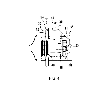
Figure 4 is a left side cut-away view of an embodiment of the disclosure.
Figure 5 is a bottom view of an embodiment of the disclosure.
(j) DETAILED DESCRIPTION OF THE INVENTION
With reference now to the drawings, and in particular to Figures 1 through 5
thereof, a new blower device embodying the principles and concepts of an
embodiment of
the disclosure and generally designated by the reference numeral 10 will be
described.
As best illustrated in Figures 1 through 5, the portable blower assembly 10
generally comprises a cylinder 12 that has an exhaust port 14 integrated into
the cylinder
12. The cylinder 12 has a rear end 16, a front end 18 and an outer wall 20
extending
between the rear end 16 and the front end 18. The rear end 16 is open and the
front end
18 is open such that the front end 18 defines the exhaust port 14. The outer
wall 20 has a
tapered section 22 extending from the front end 18 toward the rear end 16.
Additionally,
the tapered section 22 tapers inwardly toward the front end 18 such that the
front end 18
has a diameter that is less than the diameter of the rear end 16. The front
end 18 is
elongated along an axis is oriented perpendicular to an axis extending through
the rear
end 16 and the front end 18 such that the front end 18 has an ovoid shape. As
is most
3

CA 03239739 2024-03-21
WO 2022/251147
PCT/US2022/030631
clearly shown in figure 3, a mesh screen 23 may be coupled to the rear end 16
to inhibit
objects from passing through the rear end 16.
A handle 24 extends around the cylinder 12 such that the handle 24 can be
gripped
by a user for directing the exhaust port 14 toward a vehicle 24. The vehicle
24 may be a
passenger vehicle, a cargo vehicle or any other type of vehicle that has body
panels which
periodically require washing. The handle 24 comprises a ring 26 that is spaced
from and
extends around the outer wall 20 of the cylinder 12. The ring 26 is elongated
along an
axis that is oriented perpendicular to the axis extending through the front
end 18 and the
rear end 16 of the cylinder 12 such that the ring 26 has an ovoid shape. The
ring 26 is
positioned closer to the front end 18 than the rear end 16.
The handle 24 includes a pair of supports 28 that is each coupled between the
ring
26 and the outer wall 20 of the cylinder 12 for retaining the ring 26 on the
cylinder 12.
The supports 28 are positioned on opposite sides of the cylinder 12 with
respect to each
other. The handle 24 includes a member 30 that has a first end 32 and a second
end 34.
The member 30 has a bend 36 that is positioned between the first end 32 and
the second
end 34. Additionally, the first end 32 is coupled to the ring 26 and the
second end 34 is
coupled to the outer wall 20 of the cylinder 12 having the member 30 extending
from the
ring 26 toward the rear end 16 of the cylinder 12.
A blower 38 is rotatably integrated into the cylinder 12 such that the blower
38
can urge air outwardly through the exhaust port 14. In this way the air can be
directed
onto the vehicle 24 for drying the vehicle 24 when the blower 38 is turned on.
The
blower 38 is positioned adjacent to the rear end 16 of the cylinder 12 and the
blower 38
urges air inwardly through the rear end 16 and outwardly through the front end
18 when
the blower 38 is turned on. The blower 38 might include an electric motor and
a fan that
is rotatably coupled to the electric motor.
4

CA 03239739 2024-03-21
WO 2022/251147
PCT/US2022/030631
A heater 40 is integrated into the cylinder 12 such that the heater 40 is in
thermal
communication with an interior of the cylinder 12. Moreover, the heater 40 is
positioned
between the blower 38 and the exhaust port 14 such that the heater 40 can heat
the air
being blown by the blower 38. In this way the heater 40 enhances drying the
vehicle 24.
The heater 40 is positioned between the blower 38 and the front end 18 of the
cylinder 12,
and the heater 40 may comprise an electric heating coil or the like.
A blower switch 42 is provided and the blower switch 42 is movably integrated
into the member 30 of the handle 24. Additionally, the blower switch 42 is
electrically
coupled to the blower 38 for turning the blower 38 on and off. Additionally,
the blower
switch 42 might be positionable in a plurality of speed settings, ranging
between low and
high, for adjusting the speed of the blower 38. A heater switch 44 is provided
and the
heater switch 44 is movably integrated into the member 30 of the handle 24.
The heater
switch 44 is electrically coupled to the heater 40 for turning the heater 40
on and off.
A power supply 46 is integrated into the cylinder 12 and the power supply 46
is
electrically coupled to each of the blower switch 42 and the heater switch 44.
The power
supply 46 comprises at least one battery 48 that is removably integrated into
the cylinder
12, and the at least one battery 48 is electrically coupled to each of the
blower switch 42
and the heater switch 44. The power supply 46 includes a power port 50 that is
recessed
into the outer wall 20 of the cylinder 12 and the power port 50 is
electrically coupled to
the at least one battery 48. The power supply 46 includes a power cord 52 that
has a first
end 54 and a second end 56. A first plug 58 is electrically coupled to the
first end 54 of
the power cord 52 and a second plug 60 is electrically coupled to the second
end 56 of the
power cord 52. The first plug 58 is pluggable into the power port 50 such that
the power
cord 52 is in electrical communication with the power port 50 and the second
plug 60 is
pluggable into power source 62 for charging the at least one battery 48.
A pair of spouts 64 is included, each of the spouts 64 has a first end 66 and
a
second end 68, and each of the first end 66 and the second end 68 is open.
Each of the
5

CA 03239739 2024-03-21
WO 2022/251147
PCT/US2022/030631
spouts 64 tapers in diameter between the first end 66 and the second end 68.
The first
end 66 of a respective one of the spouts 64 is attachable to the front end 18
of the cylinder
12 to extend the length of the exhaust port 14. In this way the spouts 64
facilitate a large
vehicle 24, such as a semi-tractor or other similar type of vehicle, to be
dried.
In use, the handle 24 is gripped to direct the front end 18 of the cylinder 12
toward
the vehicle 24 to be dried. The blower switch 42 is turned on the blow air
outwardly
through the front end 18 of the cylinder 12 for drying the vehicle 24 when the
vehicle 24
has been washed. In this way the vehicle 24 can be dried without the need to
manually
wipe the vehicle 24, which could potentially scratch or mar the painted finish
of the
vehicle 24. Additionally, the heater switch 44 can be turned on to heat the
air blown the
by the blower 38 to enhance drying the vehicle 24. The ring 26 associated with
handle 24
facilitates the cylinder 12 to be held at a variety of different orientations
thereby
enhancing efficiency and ease of ergonomics with respect to drying the vehicle
24.
With respect to the above description then, it is to be realized that the
optimum
dimensional relationships for the parts of an embodiment enabled by the
disclosure, to
include variations in size, materials, shape, form, function and manner of
operation,
assembly and use, are deemed readily apparent and obvious to one skilled in
the art, and
all equivalent relationships to those illustrated in the drawings and
described in the
specification are intended to be encompassed by an embodiment of the
disclosure.
Therefore, the foregoing is considered as illustrative only of the principles
of the
disclosure. Further, since numerous modifications and changes will readily
occur to
those skilled in the art, it is not desired to limit the disclosure to the
exact construction
and operation shown and described, and accordingly, all suitable modifications
and
equivalents may be resorted to, falling within the scope of the disclosure. In
this patent
document, the word "comprising" is used in its non-limiting sense to mean that
items
following the word are included, but items not specifically mentioned are not
excluded.
A reference to an element by the indefinite article "a" does not exclude the
possibility that
6

CA 03239739 2024-03-21
WO 2022/251147
PCT/US2022/030631
more than one of the element is present, unless the context clearly requires
that there be
only one of the elements.
7

Representative Drawing
A single figure which represents the drawing illustrating the invention.
Administrative Status

2024-08-01:As part of the Next Generation Patents (NGP) transition, the Canadian Patents Database (CPD) now contains a more detailed Event History, which replicates the Event Log of our new back-office solution.

Please note that "Inactive:" events refers to events no longer in use in our new back-office solution.

For a clearer understanding of the status of the application/patent presented on this page, the site Disclaimer , as well as the definitions for Patent , Event History , Maintenance Fee  and Payment History  should be consulted.

Event History

Description Date
Letter sent 2024-06-12
Inactive: Cover page published 2024-06-12
Compliance Requirements Determined Met 2024-06-11
Priority Claim Requirements Determined Compliant 2024-06-11
Inactive: IPC assigned 2024-05-31
Request for Priority Received 2024-05-31
Inactive: IPC assigned 2024-05-31
Application Received - PCT 2024-05-31
Inactive: First IPC assigned 2024-05-31
Inactive: IPC assigned 2024-05-31
Small Entity Declaration Determined Compliant 2024-05-23
National Entry Requirements Determined Compliant 2024-05-23
Application Published (Open to Public Inspection) 2022-12-01

Abandonment History

There is no abandonment history.

Maintenance Fee

The last payment was received on 2024-05-23

Note : If the full payment has not been received on or before the date indicated, a further fee may be required which may be one of the following

  • the reinstatement fee;
  • the late payment fee; or
  • additional fee to reverse deemed expiry.

Please refer to the CIPO Patent Fees web page to see all current fee amounts.

Fee History

Fee Type Anniversary Year Due Date Paid Date
MF (application, 2nd anniv.) - small 02 2024-05-24 2024-05-23
Basic national fee - small 2024-05-23 2024-05-23
Reinstatement (national entry) 2024-05-23 2024-05-23
Owners on Record

Note: Records showing the ownership history in alphabetical order.

Current Owners on Record
GLENN SMITH
Past Owners on Record
None
Past Owners that do not appear in the "Owners on Record" listing will appear in other documentation within the application.
Documents

To view selected files, please enter reCAPTCHA code :


To view images, click a link in the Document Description column. To download the documents, select one or more checkboxes in the first column and then click the "Download Selected in PDF format (Zip Archive)" or the "Download Selected as Single PDF" button.

List of published and non-published patent-specific documents on the CPD .

If you have any difficulty accessing content, you can call the Client Service Centre at 1-866-997-1936 or send them an e-mail at CIPO Client Service Centre.


Document
Description 
Date
(yyyy-mm-dd) 
Number of pages   Size of Image (KB) 
Abstract 2024-03-21 1 59
Claims 2024-03-21 5 189
Description 2024-03-21 7 255
Drawings 2024-03-21 5 63
Representative drawing 2024-06-12 1 6
Cover Page 2024-06-12 1 38
Patent cooperation treaty (PCT) 2024-03-26 2 213
Fees 2024-05-23 5 119
Courtesy - Letter Acknowledging PCT National Phase Entry 2024-06-12 1 586