Note : Les descriptions sont présentées dans la langue officielle dans laquelle elles ont été soumises.
73~)
DISPOSABLE AND/OR REPLENISHABLE TRANSDERMAL
DRUG APPLICATORS AND
METHODS OF MANUFACTURING SAME
Field of the Invention
This invention relates to disposable as well as
replenishable transdermal drug applicators which are
electrically powered, and to methods for making such
lo constructions. A complete electrical circuit is made
through the skin once the drug applica-tor is adhered
thereto, whereby at least one physico/chemical mass
transfer phenomenon takes place causing the drug or
medicament to migrate through the skin.
Back~round of the Invention
Re~erence -to or disclosure of devices for
transdermal delivery of drugs by application of electrical
current through the skin of a person or animal are shown
in the -following United States patents:
385,556 ~,243,052
486,902 4,325,367
588,479 4,367,745
2,493,155 ~,419,091
2,267,162 4,~74,570
`` 126i~4~
2,784,715 4,406l658
3,163,166 4,314,554
3,289,671 4,166,457
3,547,107 4,239,052
3,677,268 4,290,878
4,008,721 4,164,226
4,141,359 4,362,645
4,239,046 4,273,135
The following foreign paten-ts refer to or dis-
close transdermal delivery devices:
EPA 0060452
DE 290202183
DE 3225748
EPA 0058920
UK 2104388
Brief Description of _he Draw~
Figure 1 is a perspective view, partially cut
away, so as to illustrate the innards of a self-contained
drug applicator of the invention;
Figure 2 is a longitudinal cross-sectional view
of -the drug applicator of Figure 1, and also illustrating
in exploded view a reusable power supply which may be
provided with a programmable control and wrist watch moun-ting,
Figure 2A is a view similar to Figure 2, but
shown perspectively, in which -the power supply and the
programmable control are contained wi-thin a wrist watch
mounting havLng concentric connectors;
Figure 3 is another perspec-tive view similar to
Figure 1, bu-t showing an alterna-te cons-truction having
a pair of off-center apertures or slots for the electrical
connections in lieu of concentric elec-trical con-tacts
~i73'~
made through the use of a single cen-ter aperture so as
to enable the mounting of a new drug applicator to the
reusable power supply in a keyed or polarized manner.
Figures 4 and 5 are fragmentary perspective views
of -typical configurations of drug electrodes/reservoirs
provided on endless web substrates fed from rolled stock
material, with occlusive adhes.ive dams separating the
drug reservoirs longitudinally, as well as transversely;
Figures 6 and 7 respectively illus-trate diagram-
matically typical assemblies of drug electrodes/reservoirs
forming larger reservoir means; or forming drug gradient
with layers of both high and low drug concen-tration
within reservoirs separated by a semipermeable membrane
or reinforcing scrim.
Figure 8 is a cross-sectional view of a disposable
drug applicator with a separate subassemblied power
source and electrical conditioning means adhesively
assembled along their elec-trodes to any one typical
drug electrode/reservoir assemblies shown in Figures 6-7;
Figure 8A is a cross-sectional view similar to that
shown in Figure 8, but illus-trati.ng an alternate drug
applicator cons-tructio:n in which the outer conformal
cover has window means -through which curren-t induced
color changes or other visual feedback information can
be viewed for verification of status of the drug delivery
system, such as drug delivery taking place or having
been terminated.
Figure 9 is a cross-sectional view of an alternate
construc-tion having similarly optionally replaceable drug
reservoirs (electrodes/reservoirs), and wi-th flat
3~
batteries forming a sub-assembly wi-th electrical
connections to electronic conditioni.ng means; and
Figure 10 illustrates an endless such substrate
fed from rolled stock rnaterial upon which is provided thin
sheet electrodes for the flat batteries and other rolled,
layered materials for forrning the power-source sub-assembly
shown in Figure 9.
Description of the Preferred Embodimen-ts
It should also be noted that as a convenience in
the following description of the invention, like numerals
are representative of siimilar elements cornmon to the
various embodiments of the invention.
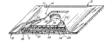
Re-ferring now to Figures 1-2, there is shown a
transdermal drug applicator 10 which is adhereed to the
skin 11 comprising an outer cover 12 with a centrally
raised portion 14 and peripheral sealed area or lip
portion 16. Such an applicator is of the replaceable type
having provision for connection to a reusable power supply
18 which may be, if desired, part of a wris-t watch
mounting having optionally a programmable control device.
Power supply 18 comprises a suitable disc baktery
20 having electrodes or terminals on opposite sides thereof.
One battery electrode is electrically connected to current
conditioning or electronic conditioning means 22 and by
means of suitable snap-on or other -type of mechanical
connectors (silver-plated Velcro connections manufactured
by Velcro Corporation of America) or by conductive and
~7~ 3
reusable adhesives; and the battery electrodes are in
turn connec-ted to conductors 24,24' extending from drug
reservoirs 26,28 which are also indicated as reservoirs
B and C, respectively. The conductors 24, 24' are
flexible suitably conductive surfaces or coatings on a
flexible plas-tic substrate 30 which is non-conductive,
impermeable, stable and otherwise compatible with drugs,
adhesives, the skin and any other materials from which
the device is fabricated. Each conductor 24, 24' with
its substrate 30 forms a seamless, one-piece, folded
member. When ben-t and folded back upon i-tself; the
plastic substrate 30 and conductive surfaces bring the
electrical contac-ts to the top side of the drug applicator
where the electrical connections are to be made with the
reusable power supply 18. The adhesive coating 32 on
the inside (and topside) of the plastic substrate 30
secures together -the ma-ting surfaces as well as the
overlapping edge or end 34 which provided with a suitable
slot or aperture 36 representing a nes-t or well area
for receiving the power supply 18 and its electrical
connectors. A small peripheral clearing 38 about the
aperture 36 represents an insulating yuard area to
preclude any possibility of shorting out. Thus the lower
electrode 40 and upper electrode 42 of the bat-tery
directly or indirec-tly make elec-trical contact with
conductors 24, 24'~ Suitable insulating material 44
surrounds the current or electronic conditioning ~eans
22, and suitable insulating material "A" which forms the
dam separating the drug reservoirs 26, 28 and provides
the end seals for not only the side of longi-tudinal edges
--6--
but also for the transverse edges oE the transdermal
drug applicator. Conformable covex 12 protects the entire
device and may be suitably of a skin tone or color and the
like appearance.
Should snaps or other type of material fasteners
be employed, it is preferable if the disposition of
same is such that the snaps are not symmetrically laid
out as such arrangement would ensure that the power
supply could only be mated in a single manner.
With the drug applicator shown being of electrode/
reservoir construction of the side by side type, the cover
need not be conductive as the lip portion merely seems
as a peripheral seal and not a return electrode. However,
it will be appreciated that the inventlon is also applicable
to drug applicators of the "matted" frame construction where
the lip portion seems as the return or inactive electrode.
In such case, then the conformable cover must also be
conductiveO
Electro kinetic mass transfer processes require
an electric power source, and in the case of electro-
phoresis an ionized drug migrates from the drug applicator
patch through the skin and into the blood stream, whereas
in the case of electroosmosis, a fluid carrier, such as
water, is likewise transported across -the skin and into
the blood stream carrying along with it any and all dis-
solved constituents (ioni~ed drugs or otherwise). Either
or both of these two physicochemical phenomena may jointly
work together or independently in transdermally carrying
a drug or drugs across the skin in a desired dosage re-
lease and/or relatively s-teady pattern.
~L~ 3~)
The application of an electrlc field across the
skin greatly enhances the skin permeability -to various
drugs.
Prior to the attachment to the skin a suitable
release liner or web 48 is removed leaving the two drug
reservoirs, insulating dam and peripheral seals free to
adhere to the skin.
It should also be understood that the power
supply 1~ is supported by a like plastic substrate 50
which is in turn suitably adhesively secured by adhesive
51 to a small conformal cover 52 which neatly covers over
and seals off the apertured area where the electrical con-
nections are made. This ensures that the device can be
worn at all times; such as in the rain or in the shower
or bath.
If desired, the reusable power supply 18 may be
part of a wrist watch 54, as shown in Figure 2A, having
a progra:mmable computer with concentric conductive
adhesive connectors 40, 42, such as previously disclosed
in said earlier patent filing with like elec-trical con-
nectio:ns and mechanical securement being provided where
needed to achieve such packaged construction. The main
difference between the disposable drug applicators shown
in Figures 2 and 2A is that the conformal cover means
12l of Figure 2A is coated with an adhesive layer 13.
Such adhesive layer 13 allows removal of the drug applicator
and replacement same as adhesive 51 in Figure 2.
The alternate construction shown in Figure 3
simply adds the fea-ture of an optimal tab 56 for the
release liner or paper 48, and the use of offset apertures
3~(~
--8--
58 and 60 for mating with the conductive adhesive con-
tacts at the bottom of battery 20 and the extended sub-
strate 50 which may be offset in a manner to provide
just side to side connection in lieu of concentric or
symetric connections.
In Figures 4-7, drug sub-assemblies are illustrated
for use with the disposable transdermal drug applicators
shown in Figures 8-9. As shown in Figures 4 and 5, the
drug reservoirs may be suitable gel layers which can be
rolled or otherwise applied to a webbed substrate fed
from endless rolled sheet material while being separated
between reservoirs and about their extreme edges by
applied occlusive adhesive dams. The dams are identified
by the Letter A and the drug reservoirs are marked with
the letters B representing negative and C representing
positive. The "quilt" type pattern where multiple drug
reservoirs are employed can be fabricated by repetitive
operative steps using a silk screen printing or transfer
process. It shouId also be recogniæed that the substrate
is coated with a suitable release agent 49, such as
silicone and when the sub-assembly is combined in-to a
complete transdermal drug applicator or patch, the sub-
strate in effect becomes the release liner 48.
Figures 6--/ illustrate the assembly of two drug
applicator sub-assemblies. For example, in Figure 6, an
optional reinforcing web or vail-like material (scrim)
62 may be used to reinforce the gel "drug" reservoirs.
One embodiment uses an open cell foam which is im-
pregnated in different areas with gel drug reservoirs
surrounded by occlusive adhesive dam penetrating the
~ ~'7~
same open cell foam. Such a structure allows the con-
struction of a thick replaceable drug reservoir in which
the gel will maintain its integrity during manufacturing,
the application to and removal from human skin, as well
as to the replacement of exhausted drug reservoirs. In
manufacture, the open cell foam web may be suitably
attached to a release liner, then provided with occlusive
adhesive dams which completely penetrate the full thickness
of the open cell foam, thus forming or designating the
drug reservoir areas which can be subsequently filled in
with their respective drug/gel mixtures.
As one 48l of the two disposed release liners can
be further discarded in production, it can be considered
optional, bearing in mind that the gel reservoirs and
dams are viscous and retain their shape, and may even be
further supported by a reinforcing web 62. Figure 7 simply
differs in that a semi-permeable membrane 64 is provided
between the two sub-assemblies so that upon assembly, drug
reservoirs are formed with areas or zones of different
drug concentration or composition. Such a type of drug
reservoir is noted to have significant advantages during
operation of the transdermal device. Note that approp-
riate seals 47 can be provlded along the semi-permeable
membranes at the edges where each reservoir ends by means
oE heat or by other means to collapse the voids and seal
the semipermeable membrane in -those areas 47 where the
seals are necessary. Alternately, silicone dams could
also be used as seals between zones of semi-permeable
materials. In addition, the semi~permeable materials
may be preimpregnated with drugs or other chemicals which
-10
might be employed. These sub-assemblies oF Fiyures 4-7
will now be shown and described as assembled onto the
sub-assembly of Figure 10. For purposes of disposability
of the drug reservoirs, these sub-assemblies (Figures 4-7)
are disposable and like replacements may be used to
replenish the drug supply.
The disposable drug applicator 70 shown in
Figure 8 comprises an optionally replaceable drug
reservoir sub-assembly 72 (any one of Figures 4-7) and a
o further sub-assembly 74 for the power means and electrical
conditioning means which assemblies are secured together
by suitable conductive adhesives. Sub-assembly 74
comprised essentially of battery 20 and current
conditioning means 22 and associated reservoir conductors
24, 24', as best shown in Figure 2. The electrical
circuit running between the drug reservoirs and through
the skin is a loop similar to that of Figure 2, the only
difference being the permanent nature of the battery and
current/electrical conditioning means in the applicator
structure rather than the reusable nature o-F the Figure 2
embodiment. However, here just the drug reservoir
sub-assembly 72 may be replaced where required~
In Figure 8A, the cover means 76 is suitably
provided with window means, as is shown, which allows the
status of the drug applicator to be observed. Such
indicator means which is observed through the window means
is more particularly described in my earlier filed U.S.
Patent No. 4,622,031. As shown in Figure 8A, the indicator
means 150 is electrically in series with the current
~2~t'3~)
conditioning means 22 and conductive surface 90 which
powers drug reservoir B. The connections of said indi-
cator means 150 to the current conditioning means 90
and the conductive surface are achieved by means of a
suitable flexible conduc-tive adhesive, as is shown at
the contact joints 152 and 154.
Figure 9 represents a like kind of disposable
drug applicator 80 having an optionally replaceable drug
reservoir sub-assembly 72, as illustrated in Figures
8-8A, and a power source or flat layered battery, as
well as electrical or current conditioning means 84 sub-
assembly which are secured together by sui-table conductive
adhesives. In this modification, the battery embodies
sheet electrodes such as carbon (+) reference number 86
and zinc (-), reference number 88 and the drug reservoir
electrodes 90, 90' which also are thin and flat. ~he
battery electrodes 86, 88 are adhesively connected to
a plastic substrate 30. The webbed material in
production is preferably folded along the illus-
trated longitudinal fold lines, 73, 73', 73", 73"' (and
others as may be required depending upon the required
number of folds) cut transversely to a predetermined
size. One carbon electrode 86 which is connected to
the drug reservoir electrode 90 forms a battery with the
large zinc electrode 88. The carbon electrode 86 which
is connected to electrode 90 could be made as one
unitary elemen-t. This large zinc electrode 88 is electrically
connected to the other carbon electrode 86 by means of
the conductive adhesive strip 87 (Figure 10) at one end
thereof, and thus forms a second bat-tery, in series with
~` ~a.2~i73fl~
the first battery, in conjunction with the small zinc
electxode 88 which is likew.ise electrically connected to
conductive surface 134 at 87l or simply with a conductive
adhesive strip s.imilar to 87.
It will be apparent to those skilled in the art
that most or all of the battery components and con-
nections within the applicator constructions of the
invention could be applied by silk screen or rotogravure
printing or, printed, die cut and stripped at high speed
on standaxd roll label equipment.
A suitable current or other electronic condi-
tioning means 84 is secured by a conductive adhesive 130
to one of the drug electrode conductive surfaces 90'
having a flexible plastic substrate 30 and is also electric-
ally connected to one of the battery electrodes, shownat 100 by means of an optional conductive indicator
150l. Optionally, a window means, such as a trans-
parent area 156 of the cover 12 or an~opening in said
cover allows the viewing of an optional indicator 150l.
In such case, the indicator 150' replaces the conduc-
tive connector~ The last battery electrode, shown at
88 is electrically connected to the other drug elec-
trode conductive surface 90 to Eorm a complete elec-
trical loop between the two drug reservoirs and through
the sk.in. ~ suitable battery electrode element 131
impregnated with a gelled battery electrolyte is
inserted between the carbon and zinc electrodes prior
to folding, and the per.ipheries of the battery compart-
ments are suitably sealed at 132 to prevent electrolyte
leakage. In this modification, the drug reservoirs are
673~
also optlonally removable if desired, as was shown in
Figures 8-8A. It should also be apparent that in this
modification, some adhesives employed may also be
conductive while in other instances it is inherent that
the adhesive has no other function than to secure
together objects so it need not necessarily be conduct-
ive and in some cases it must not be conductive or a
short circuit would occur Also, the voltage of the
battery will determine the numbers of carbon and zinc
electrodes required, and such voltage can vary depend-
ing upon the applications. Although only carbon/zinc
batteries are illustrated, other type battery cells
could be made in a similar manner.
It will be apparent to those skilled in the art
that var.ious combinations of the previously described
stages of applicator constructions can be embodied
within one drug applicator device. For example, the
function of the substrate 48' of Figures 6 or 7 could
be provided. by the electrode area 90, 90' of Figure 10
in which case the additlon of the second drug reser-
voir with its substrate (release liner 48) completes
the product. It should also be evident that the con-
struction shown in Figures 6 or 7 describes the re-
placeable drug reservoir which is employed by the end
user (patient, nurse or doctor) by peeling off the
release liner 48, applying the drug reservoir to the
area 90, 90' of power supply appl.icator construction
which results in the device shown in Figure 9 which
then could be applied on the human skin after peeling
off the release liner 48. In this particular construction,
1~'7~
~14-
it is envisioned that -the battery life will be suf-
ficient for the use of the applicator of E'igure 9
with a predetermined number of "refills" (similar to
Figures 6 or 7) when marketed together in kit form.
The same would hold true for all the other alternate
constructions and embodiments of the invention. The
power supply and the current regulating or electronic
conditioning means is designed to perform only for a
predetermined nurnber of "refills" so as to guarantee
medical supervision for each set of treatments (kit).
A current limiting resistor, in series with
the battery can be manufactured by controlling the resis-t-
ance of the conductive surfacesO Thus, such use would
make the device fail safe and could provide current
regulation in addition to or instead of solid state
conditioning means 22 of E`igure 8. Therefore, if the
currer~t conditioning means 22 of Figure 8 short circuits
th.is resistor will limit the current to a safe value
or level.
Although the present invention has been described
in some detail by way of illustration and example for
purposes of clarity and understand.ing, it will, of
course be understood that various changes and modi-
fications may be made in the form, details, and
arrangements oE the parts without depart.ing f.rom the
scope of the invention as set forth in the following
claimsO