Note : Les descriptions sont présentées dans la langue officielle dans laquelle elles ont été soumises.
~ '7~ 3~0-~4-003/0162~
JOYSTICK C0MTROLLER FOR n~ AXIS CONTROL OF A POWq~-ED EI~E~
BACKGROUND OF I~ NVENrIO~
is invention concerns joystick controllers and more particularly
joystick controllers used to control X, Y, and Z axis motion of a
powered element, such as the probe shaft of a coordinate measuring
machine, or the cutting tool of a three axis machine tool.
s
Coordinate measurement machines are known which utilize a probe
shaft mounted for vertical movement on a carriage (referenced as Z
axis motion~, which carriage in turn is mounted for movement along
two orthogonal axes in a horizontal plane (referenced as X - Y
motion).
The probe shaft is provided with a tip which is adapted to contact
points on an object supported on a table surface and, as the probe
tip is moved along the X, Y, and Z-axes, measurements of the object
are achieved by transducer means measuring this movement along each
axis.
In some machines, the probe is powered to be driven to move from
point to point about the object to be measured and it is necessary
to provide a controller for the operator if the motion is manually
controlled.
Joystick controllers have heretofore been known in which pivoting of
a joystick shaft in either of two orthogonal directions produces
corresponding X - Y movement of the probe shaft. A separate
controller has been used to produce up-down motion of the probe
shaft. Since the operator needs to activate a "record" button and
operate two separate controllers, the process is somewhat
cumbersome. Three axis controllers are also known in which a rotary
motion is utilized to achieve a Z axis motion. In this instance,
there is not instinctive corresponding movement of the controller
joystick and the probe shaft, requiring significant experience for
operator proficiency to be achieved.
With such controllers, it is necessary that a null position be
, ' : ' .,
- ~30~ -003/0162E
reliably repeatable with a reasonabLe degree of accuracy and some
means must be provided to preclude inadvertent motion in two axes as
the joystick moves in the third direction.
SUMMARY OF THE INVENTION
The present invention comprises a joystick controller for coordinate
measuring machines or machine tools in wllich a joystick shaft is
mounted for tilting movement in either of t~o orthogonal directions
with an operator graspable joystick handle assembly. The joystick
handle assembly includes a component mounted for up-down movement in
a direction aligned with the longitudinal axis of the handle. Each
mode of joystick handle movement causes an associated X, Y~ or Z
axis signal genera-tor such as a rotary potentiometer, to be
actuated, to create corresponding control output signa-ls. ~hese
]5 $ignals are utilized to actuate the corresponding coordinate
measuring machine or machine tool servo motors through suitable
means.
The handle motion alone allows motion control along all three axes,
and this motion of the joystick handle closely corresponds to the
resulting motion of the probe shaft or cutting tool. A high degree
of operator proficiency is thus readily achievable.
In a first embodiment, the joystick shaft moves through slots in
orthogonally arranged bails, which operates respective
potentiometers, utilized to generate electrical control signals
corresponding to the position of the joystick in either direction,
in a manner known in the art. However, an inner plunger is attached
to a joystick handle slidably received over the upper end of the
joystick sha~t. The inner plunger extends downwardly out of the
joys~ick shaft and at its lower end drivingly engages an operator
arm of a Z axis potentiometer assembly attached to the lower end of
the joystick shaft. Up and down motion of the joystick handle and
inner plunger actuates the Z axis potentiometer through the arm,
with a centering mechanism associated with the potentiometer wiper
to establish a precise null position.
In a second embodiment, the inner plunger directly actuates the Z
'7~;~
3~0-8~-003/0162E
axis potentionleter by a gear rack, and opposed centering springs are
arranged in the joystick handle, attached to the joystick shaft, to
center the pl~mger itself in a null position, wi-th the plLInger
operated by an attached separate operating ring located above the
joystick handle.
An advantage of the joystick controller according to the present
invention is that three axis motion control is achieved by motion of
the controller wllich corresponds to the three axis motion of the
probe shaft of a coordinate measuring machine or the cutting tool of
the machine tool.
Another advantage of thc joy~tick controller according to the
present invention is that a reliablej accurately repeatable Z axis
nulling o the joystick position is achieved.
- Another advantage of the joystick controller according to thepresent invention is that a pre-loaded null is maintained in the X,
~ Y, and Z-axes such that an operator may easily actuate one axis
without inadvertently operating the two remaining axes.
DETAILED DESCRIPTION OF THE INVENTION
FIGURE 1 is a perspective view of a coordinate measuring machine
and joystick controller according to the present invention.
FIGURE 2 is a side elevational enlarged view of a joys-tick
assembly incorporated in the joystick controller shown in FIGURE 1.
FIGURE 2A is a fragmentary endwise view of the mounted X axis
potentiometer shown in FIGUR~ 2.
FIGURE 2B is a fragmentary endwise view of the centering spring
for the X axis potentiometer shown in FIGURE 2.
FIGURE 3 is a front elevational view of a joystick assembly
incorporated in the joystick controller shown in FIGURE 1.
FIGURE 3A is an exploded perspective view of the Z axis
3L~ J~ 3
380-84-003/oL62E
potentiooleter assembly and associ~ted actuator components included
in the joystick controller shown in FIGURES 2 and 3.
FIGURE 4 is a side elevational enlarged view of an alternate
embodiment of a joystick assembly for a joystick controller
according to the present invention.
FIGURE 5 is a partially sectional enlarged view of a joystick
handle and plunger components incorporated in the joystick assembly
shown in FIGURE 4.
FIGURE 1 shows a coordinate measuring machine 10, including a base
12 having a bottom portion 14 having ~eet 16 adapted to rest on a
supporting surface 18. The base 12 also includes a table portion 20
having an upper surface 22 adapted to support an object to be
measured.
probe shaft 24 having a probe tip 26 is adapted to be moved to
allow the probe tip 26 to be placed in contact with points of
interest on an object to be measured. The probe shaft 24 is
supported for movement along a first horizontal, or X axis, by being
mounted on a carriage 28 moveably mounted on an X-beam 30. X-beam
30 is mounted on the upper ends of upstanding members 32 located on
either side of the table portion 20. The lower ends of members 32
are supported on ways 34 affixed to the base 12 which extend
orthogonally ~o the X-beam 30 and by bearings 36 which establish
guided movement of the X-beam 30 along a second hori~ontal, or Y
axis.
The probe shaft 24 is also mounted for vertical movement on carriage
28 by a suitable conventional arrangement, the details of which are
not shown in FIGURE 1.
Thus, the probe shaft 24 is moveable along three orthogonal axes
such that the probe tip 26 can be moved in three dimensions about an
object on the upper table surface 22! to measure points of interest,
in the manner well known to those skilled in the art.
380-84-003/0162E
The joystick controller 38 according to -the present invention is
adapted to enable operator controlled powered movement of the probe
shaft 2Z upwardly from a central location oE a controller hoLIsing 4Z.
A "record" button 44 is also provided to electrically control a
measurement point as well as an emergency stop button 45, each
acting in the manner well known in the art.
The joystick handle assembly 40 is mounted to be tilted back and
forth along either of two orthogonally related axes from a central
null position, with the axis of each lying in a horizontal plane
~ith controller housing 42 resting on a horizontal support sur~ace
46.
The joystick han~le assembly 40 is also able to be moved up and down
along a third orthogonal, or Z axis, aligned with its longitudinal
axis.
Signal generator means are associated with each mode of movement of
the joystick handle assembly 40, as will be described, to generate
electrical signals corresponding to the extent and direction of
movement along each axis from a central null position. These
signals are transmitted to the coordinate measuring machine 10 via a
cable 48, which may also carry leads from the record button 44, and
cause respective drive motors to be energized to drive the X-beam
30, carriage 28, or probe shaft 24 in a corresponding direction and
at a velocity corresponding to the extent of movement ~rom the null
position along the particular axis.
It can be appreciated from viewing FIGURE 1 that the movement of
the joystick handle assembly 40 closely corresponds to movement of
the probe shaft 24 such that an operator can readily achieve a high
degree of proficiency.
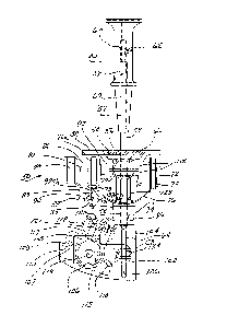
FIGURE ~ illustrates the joystick assembly 50 incorporated in the
joystick controller 38 of FIGURE 1. The details of the X and Y
axis components are well known in the art, but are here described
for the sake of clarity~ Joystick assembly 50 includes a body
~ 7~ 3 - 380-84-003/0162E
member 52 aclapted to be moun-ted to -the controller housing 42 shown
in FI~nRE 1, having a central depressed region 54 with centered
opening 56 through which extends a hollow joystick shaEt 58.
The joystick handle assembly 40 includes a joystick handle member 60
sIidably mounted on the upper end 57 of the hollow joystick shaft 58
received in a corresponding bore 59. The upper end of plunger 64
extends within -the hollow joystick shaft ~8 and is attached to the
joystick handle member 60 by set screw 62 and by screw threads on
joystick handle member 60 and plunger 64 respectively.
~ttached to the joystick handle mem~er 60 is a pivot ball 66 ~ounted
between a pair of ball socket members 68 secured to the underside of
depressed region 54 by screws 70. Pivot ball ~6 is allowed to pivot
in ball socket members 68 to allow ~iIting movement of the hollow
joystick shaft 58 and joystick handle member 60 along the X and Y
axis.
The body member 52 includes a pair of spaced side plates 72 on which
are pivotally mounted hubs 74, in turn having affixed thereto either
end of curved X axis bail 76 having a central slot 80 extending
transversely to the X axis ~FIGURE 3).
The intermediate section of the hollow joystick shaft 58 passes
through the central slot 80 which thereby accommodates Y axis
tilting motion of the hollow joystick shaft 58 parallel -to central
slot 80, with no corresponding movement of the X axis bail 76.
Thus, X axis tilt transverse to the central slot 80 causes
corresponding rotation o the X axis bail 76 and hubs 74.
The hub 74a to the left as viewed in FIGURE 2 is attached to the
protruding wiper end portion 82 of the X axis rotary potentiometer
assembly 84, which is affixed to the side plate 72a to the left as
viewed in FIGURE 2 by a mounting plate 86 and a flange 85, flange
85 rotatably fixed to the X axis rotary potentiometer assembly 84.
Thus the X axis bail 76 constitutes means drivingly connecting the
; hollow joystick shaft 58 with the X axis rotary potentiometer
assembly 84 to cause the wiper end portion 82 to be rotated upon X
~L~ 3 380-~4-003/0l6ZE
axis tilting movement thereo~.
FIGURE 2A shows that screw 89 passes through a slot 87 in ~lange
85 and is threadably received in a tapped hole in mounting plate 86
to allow adjustable anchoring of X axis rotary potentiometer
assembly 84 in adjusted angular positions.
FIGURE ZB shows that a centering spring 88 is mounted across
pivoted legs 92a and 9Zb, which each act on a pin 75 carried by hub
74a to bias the wiper end portion 8Z to a null position against a
fixed stop tab 90 formed in mo~mting plate 86. Centering spring 88,
acting Oll each leg 9Za, 92b, acts to resist rotation of X axis bail
76 therefrom in either direction.
A bracket 94 is clamped to the lower end of hollow joystick shaft 58
by cap screw 96 extending through split clamping webs 97 (FIGURE
3) so as to be mounted for movement therewith as the joystick
handle assembly 40 is tilted along the X or Y axis.
A key plate 98 is affixed to the upper surface of top plate 100
forming part of the bracket 94 with cap screw l02, key plate 98
extending along X axis bail 76 to prevent rotation of bracket 94 on
the hollow joystick shaft 58.
FIGURES 2 and 3 show that top plate 100 extends laterally to
of~set a side plate 104 integral with brac~et 94, to which is
mounted Z axis signal generator means comprised of a Z axis
potentiometer assembly 106, by mounting plate 108 and screws 110
passing through elongated openings 107 in mounting plate 108. rne Z
axis potentiometer assembly 106 passes through a slot 135 cut into
the side plate 104.
FIGURE 3A shows the components of the Z axis potentiometer
assembly 106, which is typical of each of the X, Y and Z axis
potentiometers, and includes a rotary potentiometer 109 having a
protruding wiper shaEt 114 passing through openings in a ~lange 103,
mounting plate 108, washer 105 and threaded to receive retainer nut
lll. Wiper shaft 114 also passes through openings in centering legs
~ ,;,,7~ 380-84-003/0162E
118, and an actuator arm 112 and a potentiometer actuating element
116 secured to actuator arm 112 with screws 117.
The Z axis potentiometer assembly 106 is actuated by an actuator arm
llZ and a potentiometer actuating element 116 secured thereto with
screws 117 and pin 113.
The potentiometer actuating element 116 is locked to the wiper shaft
114 with a set screw 115, while a drive pin 119 passes between
centering legs 118. A centering spring 120 is attached to either
leg 118 biasing them against a tab 121 passing therebetween, tab 121
fonned integrally with mounting plate 108. k locking screw lZ3
passes through ~n arced slot 125 and into threaded IIGIe 127 to allow
angulaE adjustment o~ the rotary potentiometer 109. Pin I29 of
rotary potentiometer 109 extends into slot 131 of flange 103 to fix
t~ese components together. FIGURE 3 shows that legs 118 are bent
to locate the centering -spring 120 to clear side plate 104 during
pivoting move~lent of the actuator arm 112.
An endwise slot 124 is formed in the end of the actuator arm 112,
which in turn is engaged by the angled end 122 of the plunger 64, so
that means are provided for causing rotation of the actuator arm 112
to be produced by up and down movement of the plunger 64.
The angled end 122 of plunger 64 extends into a vertical slot 126
fonned throu~h plate side 104 extending to accon~odate tlle full up
and down travel of the plunger 64, to maintain the orientation of
the angled end 122 and its engagement with endwise slot 124
throughout its range of movement.
FIGUR~ 3 also shows that a Y axis bail 128 is also provided,
having its ends fastened to hubs 130, each pivotally mounted to side
plates 132 of body member 52. A Y axis potentiometer assembly 134
is mounted to the side plate 132a, on the left with a potentiometer
wiper 136 secured to hub 130a on the left so as to be rotated by the
Y axis bail 128 as it pivots with hubs 130. This arrangement
provides means for drivingly connecting the hollow joystick shaf~ 58
and Y axis potentiometer assembly 134.
-- 380-84-003/0162F
~L~'7~7~3
Y axis bail IZ8 is slotted at 138 (~IGURE 2), to allow passage of
the hollow joystick shaEt 58 therethrough, and to accon~nodate
movement of the X axis potentiometer assembly 84.
A centering spring assembly 140 including a centering spring 142 is
also included to bias the potentiometer wiper 136 to a null
position, resisting rotation in either direction.
Thus, the joystick handle assembly 40 may be independently tilted in
either direction along the X or Y axis, and an electrical control
signal generated by the respecti~e X or Y a~is potentiometer
assemblies 84 or 134, in conventional fashion.
~owe~er, upon up or ~own movement o the joystick handle assembly
40, the plunger 64 is caused ~o move ~p or dor~n and actuate the
axis potentiometer assemb~y 106 to generate corresponding control
signals. Thus, the }iandle mo-tion corresponds closely to the desired
motion o~ the probe shaft 24.
FIGURE 4 illustrates an alternate arrangement in which the plunger
64 extends through the separate joystick handle member 60a and is
affixed to another handle member comprised of an operator ring 144
included in the joystick handle assembly 40 which may receive an
operator's thumb at the same time as the joystick handle assembly 40
is grasped.
Plunger 64 extends through the lower end of hollo~ joystick sl1aft 58
clamped to bracket 150, and is formed at its lower end wi-th a gear
rac~ 1~6 mating with a rotary actuator gear 148 secured to the wiper
shaft 114 of Z axis potentiometer assembly 106. Up and down
movement of the plunger 64 thus causes rotation of the wiper shaft
114 by means of the gear rack 146 and rotary actuator gear 148 and
generation of corresponding control signals, as in the previously
described embodiment.
FIGURE S illustrates the centering arrangement for biasing the
plunger 64 to a null position, wllich arrangement is contained within
a cavity 152 in the separate joystick handle member 60a.
f ,1~ ~ ~
~ J 7~)~ 380-~4~003/01621-
^ 10 -
The plunger 64 extends entirely throllgll the cavity 152 within a pair
of opposing centering springs 154 positioned above and below a
feature comprised of a web 156, wi~h one end seated against a
respective end wall 1.58 and 160 of joystick handle member 60.
A pair of washers 162 are interposed between a respective other end
of each centering springs 154 and one side of web 156.
~le plunger 64 is formed with a feature comprised of an intelmediate
shoulder 164 of the same thickness as web 156 such-that plunger 64
is biased to a null position in.which the intermediate shoulder 164
is vertically aligned with the web 156 by the centering springs 154
acting through washers 162.
1.5 Thus, centering means are thereby provided so that plunger 64 may be
accurately returned to a null centered position, .and is able to
resist inadvertent movement away from this position as the joystick
handle assembly 40 is tilted along the X or Y axis.
.
It should be appreciated that the joystick controller 38 according
to the present invention is useable with coordinate measuring
- machines of many different configurations than the machine described
herein~ or with other machine tool machines by which three axis
controlled movement of tools is achieved.