Sélection de la langue

Search

Sommaire du brevet 1273688 

Énoncé de désistement de responsabilité concernant l'information provenant de tiers

Une partie des informations de ce site Web a été fournie par des sources externes. Le gouvernement du Canada n'assume aucune responsabilité concernant la précision, l'actualité ou la fiabilité des informations fournies par les sources externes. Les utilisateurs qui désirent employer cette information devraient consulter directement la source des informations. Le contenu fourni par les sources externes n'est pas assujetti aux exigences sur les langues officielles, la protection des renseignements personnels et l'accessibilité.

Disponibilité de l'Abrégé et des Revendications

L'apparition de différences dans le texte et l'image des Revendications et de l'Abrégé dépend du moment auquel le document est publié. Les textes des Revendications et de l'Abrégé sont affichés :

  • lorsque la demande peut être examinée par le public;
  • lorsque le brevet est émis (délivrance).
(12) Brevet: (11) CA 1273688
(21) Numéro de la demande: 1273688
(54) Titre français: COMMUTATEUR DE DIAGNOSTIC
(54) Titre anglais: DIAGNOSIS SWITCH
Statut: Périmé et au-delà du délai pour l’annulation
Données bibliographiques
(51) Classification internationale des brevets (CIB):
  • G08B 29/00 (2006.01)
  • B60Q 01/00 (2006.01)
  • G01R 31/28 (2006.01)
  • G07C 05/08 (2006.01)
  • G08B 29/14 (2006.01)
(72) Inventeurs :
  • OHISHI, TATSUO (Japon)
  • FURUHASHI, HIROSHI (Japon)
(73) Titulaires :
  • SUZUKI MOTOR CORPORATION
(71) Demandeurs :
  • SUZUKI MOTOR CORPORATION (Japon)
(74) Agent: KIRBY EADES GALE BAKER
(74) Co-agent:
(45) Délivré: 1990-09-04
(22) Date de dépôt: 1987-09-23
Licence disponible: S.O.
Cédé au domaine public: S.O.
(25) Langue des documents déposés: Anglais

Traité de coopération en matière de brevets (PCT): Non

(30) Données de priorité de la demande:
Numéro de la demande Pays / territoire Date
61-146112 (Japon) 1986-09-24

Abrégés

Abrégé anglais


ABSTRACT OF THE DISCLOSURE
DIAGNOSIS SWITCH
A diagnosis system has a diagnosis switch, and has a
controller actuated by the switch for checking the opera-
tion of sensors and circuits and for lighting an alarm lamp
in accord with a coded lighting signal, the number of times
the alarm lamp is lit indicating the result of the diag-
nosis. The diagnosis switch includes a pair of diagnosis
terminals which are similar to a pair of fuse terminals and
are provided in a fuse box or in a joint box having a fuse
box, and includes a spare fuse which can be inserted into
the diagnosis terminals so as to produce a signal to the
controller for starting the diagnosis.

Revendications

Note : Les revendications sont présentées dans la langue officielle dans laquelle elles ont été soumises.


-6-
The embodiments of the invention in which an exclusive
property or privilege is claimed are defined as follows:
1. A diagnosis system, comprising a diagnosis switch
and controller means actuated by said switch for checking
the operation of sensors and circuits and for lighting an
alarm lamp in accord with a coded lighting signal, the
number of times said alarm lamp is lit indicating the
result of the diagnosis; wherein said diagnosis switch
includes a pair of diagnosis terminals which are similar to
a pair of fuse terminals, are connected to said controller,
and are provided in a fuse box or in a joint box having a
fuse box, and includes a spare fuse which can be inserted
into said diagnosis terminals so as to electrically short
circuit them in order to actuate said diagnosis system.

Description

Note : Les descriptions sont présentées dans la langue officielle dans laquelle elles ont été soumises.

~7~
DIAGNOSIS SWITCH
FIELD OF THE INVENTION
The present invention relates to a diagnosis switch
for actuating a diagnosis system~
BACKGROUND OF THE INVENTION
Various proposals have been made concerning diagnosis
systems having controllers with a self-diagnosis function
for sensor systems.
Figure 3 is a block diagram showing an example of an
existing diagnosis system, and Figure 4 is a waveform chart
which depicts a phase of operation of the system.
In Figure 3, reference numerals 11 to 19 denote
various sensors, reference numeral 2 denotes a controller,
reference numeral 3 denotes a lamp, reference n~eral 4
denotes an ignition switch, reference number 5 denotes a
fuse, reference numeral 6 denotes a battery, reference
numeral 7 denotes a connector, and reerence numeral 8
denotes a diagnosis switch.
A diagnosis system is a system which performs self-
diagnosis for the various sensors 11 to 19, the output
signals of which are input to the controller 2. In this
example, signals from sensors such as an 2 sensor 11, a

3~
.
water temperature sensor 12, a throttle sensor 13, an
intake air temperature sensox 14, and an air flow meter 15
are input to the controller. Other signals which are input
to the controller include a turbo-supercharging pressure
signal and an ignition signal.
The result of the diagnosis is displayed by lighting
the lamp 3. The diagnostic checking is started by turning
on the ignition switch 4 and simultaneously turning on the
diagnosis switch 8 provided for the checking (Figure
4 (a)). A diagnosis code is output by turning the lamp 3
on and off a certain number of times in a certain timing
pattern. From among the codes to which the sensors 11 to
19 correspond, a diagnosis code is output three times, in a
sequence starting with the smallest code number. Eor
example, in the case of the throttle sensor 13, the lamp 3
is caused to flash in accordance with the code signal shown
in Figure 4 (b~ to indicate that a specific abnormality has
occurred in the throttle sensor 13.
When a sensor is diagnosed as abnormal during the
diagnostic operation, the lamp 3 is lit so as to indicate
the abnormality to an operator.
One of the problems of this exlsting diagnosis system
is that, because the exclusive switch 8 has to be provided
to actuate the diagnosis function, an inc~ease in produc-
tion costs results and additional space for the switch is
needed.
In addition, although the exclusive connector 7 is
provided, it is often the case with this connector that it
is not particularly located in a fixed place. ConsPquently,
it has been difficult to find the connector 7 when it is to
be used. Further, when there are other connectors, it has
been difficult to distinguish with certaint~ the connector
for the diagnosis. If the connector is fixed at a certain
location with the view to avoiding these problems, this may
again lead to an increase in production costs.

~.~736~38
--3--
Figure 5 shows an example of a different existing
diagnosis switch. In particular, wher~ no exclusive switch
8 is provided, a short-circuiting connector 80 comprising a
lead wire 81 and a connector element 82 has to be provided
for each operator.
An object of the present invention is to provide a
diagnosis switch in which a part of a fuse box is utilized~
to thereby solve the problems such as those involving the
fixing position and any increase in production costs.
SUMMARY OF THE INVENTION
In order to achieve the above-stated object, according
to the present invention a diagnosis switch for a system of
the above-mentioned type includes a pair of diagnosis
terminals which are similar to a pair of fuse terminals and
which are provided in a fuse box or in a joint box having a
fuse box, and includes a spare fuse which can be inserted
into the diagnosis terminals so as to obtain a signal for
starting the diagnosis system.
BRIEF DESCRIPTION OF THE DRAWINGS
A preferred embodiment of the present invention will
now be described in detail with reference to the drawings,
in which:
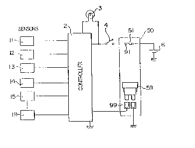
Figure 1 is a schematic block diagram of a diagnosis
system having a diagnosis switch according to the present
invention;
Figure 2 is a diagrammatic view of a fuse box and
cover which are components o the system of Figure 1 and
are provided with a pair of terminals serving as part of
the inventive switch;
Figure 3 is a schematic block diagram of an existing
diagnosis system;
Figure 4 is a waveform chart illustrating a phase of
operation of the system of Figure 3, and
Figure 5 is a fragmentary block diagram showing
another existing diagnosis system.

3 ~ ~
DETAILED DESCRIPTION
Figure 1 is a view showing a diagnosis system having a
diagnosis switch in accoxd with the present invention.
Figure 2 is a view showing a fuse box which is provided
with a pair of terminals constituting the inventive switch.
Components of the system which have the same functions
as those of corresponding components in the above-described
existing system are designated by the same ref~rence
numerals.
According to the present invention, a part of a fuse
box 50 is utilized to provide a pair of terminals 99 for
the diagnosis which are similar to each of several pairs of
fuse terminals 91 to 98. Here, the term "fuse box 50" is
used to also include a joint box having a fuse box. The
terminals 99 are connected to the contxoller 2.
A cover 50a of the fuse box 50 usually carries on the
reverse side thereof spare fuses 59 which arer for in-
stance, two 10 A and 20 A spare fuses. Therefore, at the
time of a diagnostic operation, one of these spare fuses 59
is inserted into the terminals 99 so as to short them and
thereby provide the switching function.
The cover 50a has labels 91a to 98a which indicate the
respective ampere limits of fuses for the pairs of ter~
minals 91 to 98. If a label 99a such as "DI~G", indicative
of the pair of diagnosis terminals 99, is also provided in
a similar manner, this will enable these terminals to be
visually distinguished with ease at the time of a diagnss-
tic operation.
As described above in detail, according to the present
invention an exclusive pair of diagnosis terminals are
provided in the fuse box, thus facilitating the locating of
the terminals at the time of a diagnostic operation, and
thereby facilitating the diagnostic operation.
Since the switching function is effected with a spare

~ 3 ~
fuse, no exclusive short-circu~ting connector is needed and
no increase in production costs i5 involved.
Although a particular prefarred embodiment of the
invention has been disclosed in detail for illustrative
purposes, it will ~e recognize~ that variations or
modifications of the disclosed apparatus, including the
rearrange~ent of parts, lie within:the scope of the present
invention.

Dessin représentatif
Une figure unique qui représente un dessin illustrant l'invention.
États administratifs

2024-08-01 : Dans le cadre de la transition vers les Brevets de nouvelle génération (BNG), la base de données sur les brevets canadiens (BDBC) contient désormais un Historique d'événement plus détaillé, qui reproduit le Journal des événements de notre nouvelle solution interne.

Veuillez noter que les événements débutant par « Inactive : » se réfèrent à des événements qui ne sont plus utilisés dans notre nouvelle solution interne.

Pour une meilleure compréhension de l'état de la demande ou brevet qui figure sur cette page, la rubrique Mise en garde , et les descriptions de Brevet , Historique d'événement , Taxes périodiques et Historique des paiements devraient être consultées.

Historique d'événement

Description Date
Inactive : CIB de MCD 2006-03-11
Le délai pour l'annulation est expiré 2005-09-06
Lettre envoyée 2004-09-07
Accordé par délivrance 1990-09-04

Historique d'abandonnement

Il n'y a pas d'historique d'abandonnement

Historique des taxes

Type de taxes Anniversaire Échéance Date payée
TM (catégorie 1, 7e anniv.) - générale 1997-09-04 1997-08-20
TM (catégorie 1, 8e anniv.) - générale 1998-09-04 1998-08-19
TM (catégorie 1, 9e anniv.) - générale 1999-09-06 1999-08-18
TM (catégorie 1, 10e anniv.) - générale 2000-09-04 2000-08-16
TM (catégorie 1, 11e anniv.) - générale 2001-09-04 2001-08-17
TM (catégorie 1, 12e anniv.) - générale 2002-09-04 2002-08-16
TM (catégorie 1, 13e anniv.) - générale 2003-09-04 2003-08-21
Titulaires au dossier

Les titulaires actuels et antérieures au dossier sont affichés en ordre alphabétique.

Titulaires actuels au dossier
SUZUKI MOTOR CORPORATION
Titulaires antérieures au dossier
HIROSHI FURUHASHI
TATSUO OHISHI
Les propriétaires antérieurs qui ne figurent pas dans la liste des « Propriétaires au dossier » apparaîtront dans d'autres documents au dossier.
Documents

Pour visionner les fichiers sélectionnés, entrer le code reCAPTCHA :


Pour visualiser une image, cliquer sur un lien dans la colonne description du document. Pour télécharger l'image (les images), cliquer l'une ou plusieurs cases à cocher dans la première colonne et ensuite cliquer sur le bouton "Télécharger sélection en format PDF (archive Zip)" ou le bouton "Télécharger sélection (en un fichier PDF fusionné)".

Liste des documents de brevet publiés et non publiés sur la BDBC .

Si vous avez des difficultés à accéder au contenu, veuillez communiquer avec le Centre de services à la clientèle au 1-866-997-1936, ou envoyer un courriel au Centre de service à la clientèle de l'OPIC.


Description du
Document 
Date
(aaaa-mm-jj) 
Nombre de pages   Taille de l'image (Ko) 
Abrégé 1993-10-07 1 17
Revendications 1993-10-07 1 21
Dessins 1993-10-07 2 32
Description 1993-10-07 5 169
Dessin représentatif 2002-03-06 1 7
Avis concernant la taxe de maintien 2004-11-01 1 173
Taxes 1995-08-31 1 63
Taxes 1996-08-26 1 71
Taxes 1994-08-30 1 58
Taxes 1993-08-12 1 45
Taxes 1992-08-18 1 44