Note : Les descriptions sont présentées dans la langue officielle dans laquelle elles ont été soumises.
75~7~3
25768~96
Backqround of the Invention
The present invention is directed to rotating wheel and
tread assPmblles for toy bullding blocks, especially building
blocks having stackable interconnectlon features as well as
hinged, interconnecting end features. One such system of building
blocks is disclosed in United Stiates Patent No. 4,606,732, issued
to Ronald Lyman on August 19, 19~6. This prior art building block
system includes a plurality of blocks, each having an array of
cylindrical projections extendin~ from one surface, and a like
array of socket-like receptacles extending from the opposed
surface for stackable interconnection with other hlocks. Also,
each block includes a pair of hinge arms extending from one end,
with a pair of detent knobs formed on the arms, and a pair of
recesses formed at the other end of each block and adapted to
engage the hinge knobs of like blocks in snap engaging, pivoting
~ashlon.
As a result of such lnterconnection features, the blocks
may be fashioned into assemblies whlch are stacked in non-
orthogonal fashion, or ~ormed into flexible, bendable, end-to-end
chains which describe arcuate formation, curves, and closed loops.
Indeed, such loops may be rotatable and movable to create rotatlng
rings, belt-like loops, and the like. Due to the fact that such
bullding block systems are relatlvaly new to the art, there are no
wheel assemblies avallable which exploit the pivotabillty,
mobility, and rotatability of such rings, loops, and other curved
block constructions. Clearly there is a need for wheel assemblies
adapted to this use, to maximize the creative and recreational
potential of hlnged building block systems.
S~ r~ of the Present lnvention
rrhe present invention generally comprises wheel asemblies and like
piVOtillg and rotating structures adapted for use with hinged block
constmction systems.
The rotatable assemblies include a wheei h~aving a peripheral annular
cylindrical surface adapted to SUppoFt building blocks joined thereabout in
hinged, end to end fashion, the wheel including annular flanges extending
radially outwardly and spaced axially to retain the blocks therebetween. A
pivot shaft extends fixedly from a first end face of the wheel, and is disposed
coaxially therewith. The opposed, second end face includes a coaxially
disposed bore dimensioned to receive a pivot shaft of another, similar wheel.
A plurality of cylindrical interconnection projections extend from the second
end face and are arrayed symmetrically about the bore. A plurality of
socket-like interconnection receptacles are formed in the second end face and
interspersed wilh the cylindrical projections. The first end face also includes
a like plurality of interconnection receptacles disposed to engage the
cylindrical projections of another like-formed wheel. Thus any two end
faces of any two confronting wheel can be joined in generally flush
engagement, so that pivot shafts may extend axially from both ends or one vf
the two-wheel assembly.
The cylindrical projections also permit connection between any wheel
and building blocks having similar interconnection features. That is, the
second end face of any wheel (opposite the shaft-bearing end face3 may be
joined to either the cylindrical projections or to the receptacles of building
blocks having like interconnection features. ~he rotatable assembly system
also includes a mounting block having similar interconnection features (snap
LYman Application~ Pa~e 3
5~73
el~g~(,ing projeclions and receptacles) and a plurality of shaft-engaging bores
e~;lellding later.llly into side portions of the mounting block. The mounting
blo~ 1~ may be incorporated into a block struc~ure using the aforementioned
irltel( onnection features, and the pivot shaft of a wheel member engaged in
olle of the boles in the rnounting block in snap-engaging, freely rotating
fllsllion. In this configuration the wheel is adapted to rotate about the pivot
sllarl witll the first end face thereof confronting the mounting block, and the
sccond end face either extending freely or joined to another block assembly.
In ~l~e latter case the wheel provides the function of a bearing, joining the two
scl~alate block constmctions with free relative rotation about a relatively
fixe(l axis thercbetween.
The wheel may also be connected to a block structure using the
illtelconnectioll features of the second end surface to join to like features oflilie blocks in fixed relationship. In such con~iguration a chain of hingedly
collllected blocks may be secured about the fixed wheel in belt or loop
fasllion, and urged to circulate about the fixed wheel in sliding translation
tllereabout. Also, the outwardly extending first end face of the wheel can be
joined to further wheels in stacked axial relationship to provide relative
rcllation therebetween.
Also, the mounting block described above may be provided with
hinged end connec~or features similar to the building blocks of the system. It
is Illen possible to connect the mounting block to a relatively fixed block
constluction in hinged relationship therebetween, so that a wheel pivot shaft
nlcly be engaged in a bore of the mounting block and disposed to freely rotate
ab(lllt an axis which is itself pivotable about the mounting block hinged
i ntel-connect.
Lyman A~ lication. Pa~e 4
~X~75~73
s it is apparent that the wheel assembly components of the present
invenlion provide a wide variety of rotatable and pivotal assemblies in
various combinalions. These varied kinetic assernblies may be joined in a
virl~lally infinite number of combinations and permutations ta provide a rich
ad(lition to the expressive possibilities of toy building blocks.
Lyn-an AI~Plication. Pa~e S
~.~7~73
Bricf l)escriptinn oF the Drawing.
~ igure 1 is a perspective view of one end surface of the wheel member
of tlle present invention.
I~igure 2 is an end elevation of one end of the wheel member depicted
in l~igllre 1.
~ igure 3 is a side elevation of the wheel member depicted in Figures 1
and 2.
Figure 4 is an end elevation of the other end of the wheel member
dcpicted in Figures 1-3.
~ igure 5 is a side elevation showing two wheel members joined in
axially stacked assembly and joined also to a mounting block of the present
invention.
Figure 6 is a side elevation of two wheel members joined to an
intermediate mounting block of the present invention.
Figure 7 is a side elevation showing an alternative combination of two
wheel mernbers joined in axially stacked assembly and joined also to a
mounting block.
Figure 8 is an end elevation of the mountin~ block member of the
present invention.
LYn1an Ar)Plication, Pa~e 6
5~7;~
I~igure 9 is a side elevation of the mounting block member depicted in
Figure 8.
Figurc 10 is a bottom view of the mounting block member shown in
Figures 8 and 9.
Figure 11 is a side elevation of a mounting block joined to a wheel
mernber in ~reely rotating fashion.
Figure 12 is an end elevation of mounting blocks joined to a wheel
member in fixed engagement.
Figure 13 is a side elevation of a rotating belt assembly formed of two
wheel assemblies of the present invention and a chain of hingedly connected
blocks joined in a loop.
Figure 14 is a side elevation of a wheel construction in which a ring of
hingedly connected blocks are connected about one wheel member of the
present invention.
Figure 15 is a side view of a wheel member connected to a bui~ding
block in interdigitating fashion.
Figure 16 is a side view of a wheel member connected to a building
block with the projections of the wheel member engaged in the socket
receptacles of the block in snap-engaging fashion.
L~man APPlication. Pa~c 7
~75~73
l~igure 17 is a side view of a wheel mernber connected to a building
block with the projections of the wheel member interdigitated with the
projections of a building block.
Figure 18 is a cross-sectional elevation showing the engagement of a
wheel assembly pivot shaft in a mounling block bore of the present invention.
Lyman APPlication. Pa~e 8
7~3
Description of the Preferred EmbQdiment
The present invention generally comprises construction block
components for forming wheel assemblies and like p;voting and rotating
stmctures. The invention is adapted for use with hinged block construction
systems, although it can be ernployed advantageously with many forms of
building blocks known in the prior art. A key component of the present
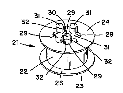
invention comprises a wheel member 21, as shown in Figures 1-4. The
wheel member 21 includes a generally cylindrical peripheral curved panel
22, and disk-like end panels 23 and 24 joined to axially opposed ends of the
panel 22. The end panels are disposed coaxially with the panel 22, and are
greater in diameter to define a pair of axially spaced annular flanges 26
extending radially from the opposed ends of the wheel. The axial spacing of
the flanges 26 is sufficient to accommodate the width dimension of hinged
interconnecting blocks as described in United States Patent No. ~ 3
mentioned in the preceding description.
Extending outwardly from the end panel 23 is a generally rigid pivot
shaft 27, disposed axially with respect to the cylinder 22 and the end panel
itself. A quartet of generally cylindrical socket-like receptacles 28 are
formed in the end panel, and arrayed symmetrically with respect to the shaft.
The receptacles are disposed at equal distances from the sha~t 27 and at equal
angles thereabout. The other end panel 24 is provided with a bore 30
extending axially therein and dimensioned to receive a pivot shaft 27 of
another like-formed wheel in freely rotating fashion. The end panel 24 is
also provided with a quartet of receptacles 29 virtually idenlical to the
receptacles 28 and arrayed in like manner in equal spacing about the bore 30.
However, the end panel 24 -further ;ncludes a quartet of cylindrical
Lvman APPlication. Pa~e 9
~.~7SJ~7~.~
projections 31, each interspersed between a pair of receptacles 29. The
projections 31 are dimensioned to in~erconnect with the receptacles 28 or 29
of other like-formed wheels. Furthermore, the projections are provided
with axially extending arcuate cutouts 32 to permit the'interdigitation of
projections 31 with like projections of similarly formed wheels.
The end panel features described above permit the direct' end-to-end
connection of a plurality of wheels 21 in many different stacked assemblies.
For exarnple, as shown in Figure 5, the cylindrical projections ~1 of one
wheel may be interdigitated with the projections 31 of anolher wheel, and the
confronting end surfaces 24 urged together so that the projections 31 of each
are received in the receptacles 29 of the other. ln this configuration the pivotshafts 27 of the two assembled wheels extend axially outwardly in opposite
direct;ons from the assembly. Alternatively, two wheel may be joined with
the end surface 24 of one confronting the end surface 23 of the other, as
shown in Figure 7. ln this configuration the pivot shaft of the latter is
received in the bore of the former, and the projections 31 of the former
received in the receptacles 28 of the latter. In ~is configuration the assembly
provides one pivot shaft 27 extending therefrom, and one surface 24 facing
exteriorly in the opposite direction and available to be interconnected with
other wheels or with blocks having similar projections and receptacles for
interconnection. Furthermore, a plurality of more than two wheels may be
assembled using either or both of the configurations of Figures S and 7, as
suits the creative needs of ~e individual using the components.
The present invention also includes a mounting block 36 adapted ~or
use Wit]l the' wheel (or wheels) 21. Each block 36 comprises a generally
rectangular solid object having an array of cylindrical projections 31'
extending from the upper end thereof and a like array of socket-like
.
Lyman APPlication, Pa~e 10
.. ...
~L~75~
receptacles 37 formed in the bottom end, the receptacles being adapted to
receive and engage the projections 31 of tlle wheels or the projections 31' of
like-formed mounting blocks 36 for stacked interconnection therebetween.
Furthermore, the toy building block system described in the United States
Patent enumerated above includes blocks having like interconneclion
features, so that the mounting block 36 rnay be incorporate~ into a block
construction according to that prior art system.
A salient feature of the mounting block 36 is the provision of a
plurality o~ shaft-engaging bores 38, each extending laterally into one of the
side panels of the rectangular block 36. Each bore 38 is dimensioned to
receive therein a pivot shaft 27 in freely rotating fashion, as shown in FiguresS and 7. With regard to Figure 18, it should be noted that the distal end of
each shaft 27 is provided with a concave recess 46 extending into the end face
thereof. Each shaft is also provided with a t~pered annular groove 47
disposed slig}ltly proximally of the inner extent of the concave recess 46.
The recess 46 and groove 47 act cooperatively to permit the elastic radial
compression of the distal end of the shaft 27.
Each bore 38 in a mounting block 36 includes a flange 49 disposed at
the inner end of the bore and extending radially inwardly. The flange 49 is
dimensioned to form an interference fit with ~he distal end of a shaft 27,
compressing the distal end radially as it is inserted thereby and snap-enga~ing
the annular groove 47. The snap-engagement of the groove is provided with
sufficient clearance to define a freely rotating engagement of the shaft.
However, it should be noted that the shaft cannot be removed from the bore
without first exerting sufficient axial force to urge the distal shaft portion
past the constriction formed by the flange 49. Thlls the shaft is retained and
prevented from inadvertent withdrawal, although it rotates freely and can be
L~Jman APPlication. Pa~e i l
~75~73
removed witl1 moderate manual effort. Furtl1ermore, a knob-like stop 48
extends perpendicularly with respect to the axis of the bore 38 and limits the
inward Iravel of tlle shaft 27 in the bore 38.
~ mounting block 36 may be disposed intermediately of a pair of
whe~ls ~1 and used to join the wheels in spaced apart, axial alignment, as
shovyn in Figllre 6. Also, one or more of the wheel members 21 of the
present invention may be supported by rnounting blocks 36 incorporated in
the buil(ling block system referenced above.
Imrthermore, each of the mounting blocks 36 includes hinged
intercolmecting end features of the relferenced patent; i.e., two pair of
arc~late recesses 39, each pair disposed at lower corner positions of each side,adjacellt to the end walls. Each recess includes a detent recess 41 adapted to
engage the pivot arms and detent knobs of the blocks 42 of the referenced
building block system. Thus each mounting block 36 may also be joined in
hinged, pivoting fashion to a chain or array of such building blocks 42, as
shown in Figure 11. Alternatively, the blocks 42 may be joined to a wheel 21
using the receptacles of the blocks 42 to receive and engage the projections 31
of tl1e wheel, as shown in Figures 12 and 16. In this latter configuration the
wheel is non-rotatable with respect to the block construction. However, as
shown in Figure 15, one projection 31 may be snap-engaged in one receptacle
of a building block 42', joining the two components in freely rotating
fashion.
It may be appreciated that the components of the present invention
provide wheel members which may be joined together in myriad possible
combinations, sllch as stacks of wheels in axial alignment, one or more
wheels supported in rotating fashion by a mounting block, and/or one or
more mounting blocks supported eitller hingedly or fixedly in a cnnstruction
Lymall APl~lication, Pa~e 12
5~73
of blocks 42 . I~he wheels may also be directly joined to a construction of
blocks 42. To a(l~l to this array of possibilit;es, the projections 31" of a block
42 may be interdigitated with the projections 31 of a wheel 21 to form an
interconnection tl1erebetween, as shown in Figure 17. Thus the limitations of
tyl ical prior art block systems can be overcome, especially concerning not
only which surf~lces of particular blocks can be interconnected, but also ~e
limitations on arcuate structures and pivoting structures of such systems. And
the present inv~ntion achieves this structural freedom using an absolute
minimum of difl~ring components.
As one example of an entertaining structure which may be formed
wi~h Ihe present invention, a pair of wheels 21 may be secured to spaced
mounting blocks incorporated into a block structure. A chain of blocks 42
may be secured about the wheels 21 in endless loop fashion, as shown in
I~igure 13, forming a belt which may be circulated about the wheels to
provide a close representation of a caterp;llar tractor tread, a conveyor belt,
dl ive belt, bicycle chain, or the like. It should also be noted that the wheelsal e formed of a plastic material having a low coefficient of friction, so that
llle loop of blocks 42 will translate easily about Ihe wheels 21 even though
the wheel may be fixedly secured to the block construction.
As anoll~er example, a plurality of the blocks 42 may be secured about
a single wheel 21 to form an endless loop thereabout. This construction may
be used to represent a gear wheel, tire tread, or the like, and will also rotateabout the wheel whether or not the wheel is fixed other block structures.
Indeed, the combinations of stacked wheel assemblies, wheel and mounting
block assemblies, and wheel and building block assemblies is infinite, and
cannot be enumerated herein.
I,YI11~11 APplication~ Pa~e 13
~.2~5~L73
..... ;
'Illus the present invention provides an enormous addition t~ the
possibilities of structllral representations in building block art, limited onlyby tlle imagination of the child or adult using the invention and the number of
wlleels and blocks available.
L~man APPlication. Pa~e 14