Note : Les descriptions sont présentées dans la langue officielle dans laquelle elles ont été soumises.
~7 7
5 ~3
An apparatus and a method for the production of ribbed
pipes
This invention relates to an apparatus for the
production of ribbed pipes having a smooth inner face,
of a plastic material, said apparatus comprising a core
which is formed by a spindle, a conically enlarging
mandrel positioned after said spindle in the production
direction of the apparatus, and a-kernel which has a
substantially constant diameter and which is positioned
after sa-id mandrel; an extrusion sleeve which surrounds
said spindle so as to-form a nozzle for the material
toge-ther with the core; and chill moulds which surround
said extrusion sleeve and said core ans which are
transportable along an endless path and the inner
surface of which is provided with grooves for the
formation of ribs on a pipe; whereby an end zone of
the kernel spaced from the nozzle is provided with
means for the cooling of said zone. The invention is
also concerned with a method for the production of
ribbed pipes.
Various apparatuses and methods have been
suggested for the production of solid-wall ribbed
pipes; none of these, however, is in industrial use on
account of some major disadvantages thereof. GB Patent
Specification ~,Z~31,796 discloses an extrusion moulding
method which is characteri~.ed by the step of creating
a rather low moulding pressure mainly by means of the
extruder. DE Patent Specifications 2 362 g44 and
1 233 l28 and FR Patent Specification 7 315 485 dis-
close injection moulding methods which are character-
ized by a small closed moulding space wherein there
prevails a high pressure. From Fl Patent Specification
60 825 and DE Patent Specification 2 709 395, such
press mou]ding me-thods are known which are character-
ized by an open moulding space and by the step of
~,7~;7~3
creating a pressure by means of the extruder on one
hand and by means of the traction force of a conically
enlarging part of the core, i.e. the mandrel, and the
chill moulds on the other hand. A similar straight-
kernel structure is also known from the manufacturingtechnique of double-walled corrugated pipes, see e.g.
CA Patent Specification 1 172 813.
A structure corresponding to the apparatus
disclosed at the beginning of this specification is
known from EP Patent Specification 0 005 104 (US Patent
Specification 4 365 948), wherein Figure 6 illustrates
an apparatus operated by the extrusion mouldlng method
and by means of which solid-wall plastic pipes having
a smooth inner face and a corrugated outer face can be
manufactured. This figure shows a kernel the cooling
means of which are positioned only at the terminal end
of the kernel, while the initial portion of the kernel
is uncooled. The kernel has a constant diameter.
A major disadvantage of the manufacturing
methods mentioned above is that it is very difficult to
produce by means thereof pipes having high narrow ribs
which would be the most advantageous ones in view of
the use of the pipe. In order that the deep narrow
grooves on the inner surface of the chill moulds were
filled up, extremely high pressures have to be applied,
which requires high durability from the apparatus.
These problems are further aggravated when a stiEf type
of plastic, such as a l'VC wLthout any soEtener, is
used.
Another major problem is the surface finish of
the inner face of the pipe. The smoothness of the inner
face is impaired by e.g. the following Eactors: air
bubbles are formed in the moulding space; the high
shearing speed causes crac]csin the melt; irregularities
and cold seams are formed due to the layer structure of
75773
the material; the inner face may adhere to the kernel;
and an uneven cooling of the substance gives rise to
recesses and air bubbles within the material. For
these reasons, it has not previously been possible to
manufacture high-quality ribbed pipes industrially by
the methbdsmentioned above.
The object of the present invention is to
provide an apparatus and a method for the production
of ribbed pipes, by means of which the pipes can be
provided with complete ribs and a smooth inner face.
The apparatus according to the invention is character-
ized in that means are provided in an initial zone of
the kernel between said mandrel and said end zone of
the kernel for the heating of said initial zone, and
that the diameter of the initial zone of the kernel
increases slightly in the direction of motion of the
material.
In the apparatus according to the invention, the
initial zone of the kernel is heated and its diameter
increases slightly towards the end zone. When the pipes
are heated still within the area of the kerne]. and the
plastic mass or material is simultaneously forced
towards the chill moulds, the material unexpectedly
fills all the grooves of the moulds reliably, and the
inner face of the pipe becomes completely smooth. The
advantageous influence of the structure according to
the invention might be due to the fact that a:Eter the
grooves of the chill moulds have becrl :Elllcd by the
action of the extrusion pressu.re w:itl~:Ln l:he area of
the conical rnandrel, -the moulds begin to chill the
material, which begins to contract. Any imperfections
caused by the different cooling rates and the
contraction oE the material are prevented by creating
a notable terminal pressure in the grooves of the chill
moulds, as a result of which the material to be moulded
i7~73
follows accurately the surfaces of the chill moulds and
the kernel. This terminal pressure is independent of
the extrusion pressure, and it is therefore easily
adjustable by changing the heating effect. The lenyth
of the initial zone of the kernel, too, affects the
terminal pressure.
The heating means can be positioned in one part
of the initial zone only, but it is of advantage in
view of the operation that the heating means of the
initial zone extend over the whole length of the zone.
For the same reason, it is desirable that the diameter
of the initial zone increases essentially evenly.
The kernel in the present description means that
part of the core which has an essentially constant
diameter and by means of which the inner face of the
pipe is calibra-ted. Therefore it is evident that the
diameter cannot vary to any greater degree. Conse-
quently, the kernel oE known apparatuses has a constant
diameter or -the diameter decreases to some extent
towards the terminal end so that a cooling, contracting
pipe would not adhere thereto. For this reason, the
diameter of the initial zone of the kernel according
to the present invention increases only slightly in
the production direction so that the diameter of the
kernel at the end oE the initial zone is 0,2 to 2,0
per cent, preferably about 1,0 per cent, larger than
at the beginning of -the initial zone.
In order -that the irllt~ l ZOllO oE the kor~
would have the clcsire(l c(:Eect on t}-le mouldlrlg of -the
pipe, i-t must be sufficiently long. ~c~cording to the
invention the length of the :ini-tial zone in the axial
direction of the appara-tus is 10 -to 100 per cent,
preEerably about 50 per cen-t, of -the outer diameter of
the pipe.
An unusually high friction exists be-tween the
material and -the kernel due to the terminal pressure.
73
Any disadvantageous effects resulting therefrom can be
eliminated by providing the kernel with a suitable
plas-tic repellent coating, e.g. by a boric treatment,
by the use of a lubricant, or by providing part of the
kernel with a low spiral-shaped groove or grooves which
prevent the material from sticking fast to the surface
of the kernel.
The invention is also concerned with a method
for the production of ribbed pipes having a smooth
inner face, of a plastic material, wherein a material
which is in a plasticized state is extruded into a
ring-shaped moulding space which is defined between the
end face of an extrusion sleeve, a core of the appara-
tus, said core comprising a spindle, a conically
enlarging mandrel and a kernel having a substantially
constant diameter, and chill moulds which surround
said extrusion sleeve and the core and move in the
production direction of the apparatus and the inner
surface of which is provided with grooves for the
formation of the ribs; the material which has been
moulded into a pipe being cooled by the chill moulds
and an end zone of the kernel.
The method according to the invention is
characterized in that the inner face of the material
being in the shape of a pipe is heated from the end
zone, and -that the diameter of the inner face of the
pipe is increased slightly in the area of the initial
zone.
One pre.Eerrcd emhocl:iment of -the invention will
be descrihed more closely below with reference to the
attached drawing, wherein
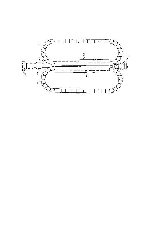
Figure 1 is a general view of an apparatus for
the production of ribbed pipes, and
Figure 2 is an enlarged longitudinal section
of one detail of the apparatus.
~75~3
The apparatus shown in Figure 1 comprises two
chill moulds 1 and 2 which move along endless paths
and which meet each other within the area of guide
rails 3 to form a cylindrical mould. An extrusion
sleeve 4 connected to an e~trusion head 6 of an
extruder 5 extends into said mould. It is also shown
in Figure 1 how a finished pipe 7 protrudes from the
other end of the mould formed by the chill moulds.
Figure 2 is a more detailed view of those parts
of the apparatus which take part in the moulding of
the pipe. A spindle 8 is positioned on the central line
of theapparatus partially within the extrusion sleeve
4, which spindle 8 is straight, i.e. it has a constant
diameter. A conically enlarging mandrel 9 is positioned
after the spindle so that it is wholly outside the
extrusion sleeve, and a kernel 10 having an essentially
constant diameter is positioned after the mandrel. The
spindle 8, the mandrel 9 and the kernel 10 together
form the core of the apparatus.
The extrusion sleeve 4 and the spindle 8 define
therebetween a ring nozæle 11 wherefrom the material to
be moulded, e.g. a plastic substance, is fed into a
moulding space 12 defined between the extrusion sleeve
4, the chill moulds 1, 2, the spindle 8 and the mandrel
9. In order to obtain a pipe having a ribbed outer face
the innersurface of the chill moulds is provided with
mutually spaced ring-shaped grooves 13 into which the
plastic material is forccd Eor thc lormltiorl o~ thc
ribs.
The kernel 10 is formed by two successive par-ts:
an initial zone 14 and an end zone 15. These zones are
separated from each other by means of a peripheral
groove 16 out of which a lubricant, e.g. air, can be
fed on the surface of the end zone 15 of the kernel.
Cooling means l7 (shown schema-tically in the drawing)
~2757~3
are provided within the end zone 15 for e.g. a liquid
coolant. The cooling means enable the surface of the
end zone 15 and, consequently, the inner face of the
pipe moulded of the material to be cooled so that the
pipe 7 keeps its shape when removed from the manu-
facturing apparatus.
The diameter of the end zone 15 is slightly
reduced from the groove 16 onwards so that the diameter
D1 is about 1 per cent larger than the diameter D2. So
this tapering is very gentle, although it has been
exaggerated in the drawing for the sake of clarity.
According to the invention the initial zone 14
of the kern~l, which zone is positioned between the
mandrel 9 and the groove 16, enlarges slightly towards
the groove 16 and is provided with heating means.
The diameter of the initial zone 14 increases
evenly from the diameter D3, which is the diameter of
the initial zone adjacent the mandrel 9, to the dia-
meter D4, which is the diameter of the initial zone at
the groove 16, so that the diameter D4 is about 1 to 2
per cent larger than the diameter D3. Although this
enlargement is very small it has proved to be of great
importance in practice. The initial zone is further
provided with heating means extending over the whole
length of the zone, which means are shown schematically
in the drawing and indicated therein by the reference
numeral 18.
The length o:E thc init:ial zonc :is lO to lO0 pc.r
cent, preferably about 50 per ccnt, of the outer dia-
meter of the pipe, and the l.ength of the end zone 15
is 50 to 200 per cent of the outer diameter of the pipe.
The chi.ll moulds 1, 2 are provided with cooling
means (not shown) for the cooling of the outer face of
the pipe.
The apparatus shown in the drawing operates in
the following way. A pressurized material to be moulded,
~;~75773
such as a plastic substance, is fed from the nozzle 11
between the extrusion sleeve 4 and the spindle 8 into
the moulding space 12, in which it is forced outwards
by the action of the conically enlarging mandrel 9 so
S that it fills the grooves 13 of the chill moulds and
the space defined between the chill moulds and the core
of the apparatus. The material which has been forced
into the gxooves 13 forms the ribs of the pipe, and the
material which remains between the chill moulds and
the core forms the wall of the pipe.
When the material makes contact with the chill
moulds 1, 2, it begins to cool, while those portions of
the material which are positioned closest to the kernel
are maintained in a plasticized state since the initial
zone 14 of the kernel is heated by said means 18. By
virtue of the heating of the material and the enlarging
diameter of the initial zone 14, the material fills
properly all the grooves 13 and becomes very homoge-
neous in the area of the initial zone, on accoun~, of
which the inner face of the pipe, too, becomes very
smooth.
After the pipe has passed by the groove 16, it
is began to be cooled also on the inside by means of
the cooling means 17, whereby the ma-terial is stiffened
to such an extent that it keeps its shape when it is
removed from the apparatus. The pipe is contracted
during the cooling step, and the encl zone o:E the kcrnel
tapers sl.ightly towa.rds the end the.r~eof .in order to
prevent the pipe from adhering to the kernel. For the
same reason, a lubricant is fed out of the groove 16 on
the surface of the end zone.
As distinct from the above-described, the
heating means 18 may extend merely over a part oE the
length of the initial zone and the groove 16 can, of
course, be left out if there is no need to feed a
~.~7Si~3
lubricdnt on the surface of the kernel. It is further
to be noted that the inclination of the surface of the
initial zone 14 has been exaggerated to some e~tent
in the drawing for the sake of clarity~