Sélection de la langue

Search

Sommaire du brevet 1279236 

Énoncé de désistement de responsabilité concernant l'information provenant de tiers

Une partie des informations de ce site Web a été fournie par des sources externes. Le gouvernement du Canada n'assume aucune responsabilité concernant la précision, l'actualité ou la fiabilité des informations fournies par les sources externes. Les utilisateurs qui désirent employer cette information devraient consulter directement la source des informations. Le contenu fourni par les sources externes n'est pas assujetti aux exigences sur les langues officielles, la protection des renseignements personnels et l'accessibilité.

Disponibilité de l'Abrégé et des Revendications

L'apparition de différences dans le texte et l'image des Revendications et de l'Abrégé dépend du moment auquel le document est publié. Les textes des Revendications et de l'Abrégé sont affichés :

  • lorsque la demande peut être examinée par le public;
  • lorsque le brevet est émis (délivrance).
(12) Brevet: (11) CA 1279236
(21) Numéro de la demande: 1279236
(54) Titre français: COMMANDE D'ACCELERATION
(54) Titre anglais: THROTTLE CONTROLS
Statut: Périmé et au-delà du délai pour l’annulation
Données bibliographiques
(51) Classification internationale des brevets (CIB):
  • B60K 26/04 (2006.01)
  • B60K 26/02 (2006.01)
  • G05G 11/00 (2006.01)
(72) Inventeurs :
  • OLD, JOHN LESLIE (Royaume-Uni)
  • SUMMERS, HARRY (Royaume-Uni)
(73) Titulaires :
  • AGCO LIMITED
(71) Demandeurs :
  • AGCO LIMITED (Royaume-Uni)
(74) Agent: GOWLING WLG (CANADA) LLP
(74) Co-agent:
(45) Délivré: 1991-01-22
(22) Date de dépôt: 1987-05-26
Licence disponible: S.O.
Cédé au domaine public: S.O.
(25) Langue des documents déposés: Anglais

Traité de coopération en matière de brevets (PCT): Non

(30) Données de priorité de la demande:
Numéro de la demande Pays / territoire Date
8613915 (Royaume-Uni) 1986-06-07

Abrégés

Abrégé anglais


ABSTRACT
THROTTLE CONTROLS
A combined hand and foot control for a prime mover throttle
member 10 including a hand control 12, a foot control 13,
and a combining device 14 for combining the hand and foot
controls. The combining device includes a plastics support
housing 14a,14b and a combining member 34 slidable within
the housing in first and second opposite directions. A
first cable linkage means connects the combining member 34
with the throttle member 10 so that movement of the
combining member in the first direction moves the throttle
member towards a fully open position, bias means 38 acting
to bias the throttle member towards an idle position and
hence bias said combining member 34 in the second direction
via the first linkage 17. A second cable linkage 16
connects the foot control 13 and combining member 34 for
movement of the combining member in the first direction, and
a third cable linkage 15 connects the hand control 12 with
the combining member 34 via a connection 15c,35a capable of
moving the combining member in the first direction only and
allowing sliding of the combining member in the first and
second directions relative to the third linkage 15. The
arrangement is such that any throttle member position set by
the hand control 12 can be increased using the foot control
13 by the second linkage 16 sliding the combining member 34
in the first direction relative to the third linkage 15.

Revendications

Note : Les revendications sont présentées dans la langue officielle dans laquelle elles ont été soumises.


CLAIMS
1. A throttle control for a prime mover comprising a prime
mover throttle member, a hand control, a foot control,
a combining device including a support member and a
combining member movable relative to the support member
in first and second opposite directions, first linkage
means connecting the combining member with the throttle
member so that movement of the combining member in said
first direction moves the throttle member towards a
fully open position, bias means acting to bias the
throttle member towards an idle position and hence bias
said combining member in said second direction via the
first linkage means, second linkage means connecting
the foot control and combining member for movement of
the combining member in said first direction, and third
linkage means connecting the hand control with the
combining member via a connection capable of moving the
combining member in said first direction only and
allowing movement of the combining member in said first
and second directions relative to the third linkage
means, the arrangement being such that any throttle
member position set by the hand control can be
increased using the foot control by said second linkage
means moving the combining member in said first
direction relative to said third linkage means, said
combining member being movable in a slidable manner
relative to the support member and relative to the
third linkage and the foot control being movable with
the combining member when the hand control is moved in
said first direction.

2. A control according to claim 1 in which the support
member comprises a housing within which a combining
member in the form of a slidable block is supported.
3. A control according to claim 1 in which each linkage
means includes a Bowden cable to permit easy
installation of the control.
4. A control according to claim 3 in which the outer of
each cable is held captive by the housing and the inner
of each cable is connected with the slidable block.
5. A control according to claim 4 in which the slidable
block is provided with three slots which extend end to
end of the block in directions parallel to said first
and second directions, each slot being arranged to
receive a respective Bowden cable inner loosely
slidable therein and each inner being connected with
the block by abutment of a nipple thereon with a
respective end face of the block to transmit motion to
the block by tension of the inner.
6. A control according to claim 2 in which the housing and
slidable block are made from plastics material.

Description

Note : Les descriptions sont présentées dans la langue officielle dans laquelle elles ont été soumises.

lZ79236
THROTTL~ CONTR~L
This invention relates to throttle controls and in
particular to combined hand and foot controls which allow
the posltion of a throttle member of a prime mover to be
adjusted by both an operator's hand and fo~t.
Such combined hand and foot controls are common on agri-
cultural tractors to adjust the position of a throttle lever
on a diesel engine fuel injection pump but are freguently
relatively complex in construction and because of a tendency
to use rigid links often require to be tailored for each
particular tractor in a given tractor manufacturers range.
An alternative arrangement which makes use of flexible
linkages i~ disclosed in ~S-H- 525~09. The hand and foot
throttle controls are each connected to a governor for
control thereof without any interaction between the throttle
controls. Each throttle control is connected to the
governor by a separate linkage incorporating a flexible
cable capable of transmitting force by tension but not
compression. Thus if one cable is tensioned through a
manipulation of the associated throttle control the cable of
the other throttle control goes slack and transmits no
motion to the manipulated throttle control. When the hand
throttle control is used to open the governor setting the
cable connected to the foot thrott~e remains slack, and
indeed actually slackens off further. If the operator
should wish to override the ~and throttle control setting he
must first depress the foot pedal sufficiently to take up
any slack in the cable and t~en depress the pedal even
furt~er to increase the throttle setting. This arrangement
lacks an instant response on the override facility.

1279236
It is an object of the present invention to provide an
improved combined hand and foot control for a throttle
member which is suitable for use on a tractor diesel engine
and which mitigates the above problems.
Thus according to the present invention there is provided a
throttle control for a prime mover comprising a prime mover
throttle member, a hand control, a foot control, a combining
device including a support member and a combining member
movable relative to the support member in first and second
opposite directions, first linkage means connecting the
combining member with the throttle member so that movement
of the combining member in said first direction moves the
throttle member towards a fully open position, bias means
acting to bias the throttle member towards an idle position
and hence bias said combining member in said second
direction via the first linkage means, second linkage means
connecting the $oot control and combining member for
movement of the combining member in said first direction,
and third linkage means connecting the hand control with the
combining member via a connection capable of moving the
combining member in said first direction only and allowing
movement of the combining member in said first and second
directions relative to the third linkage means, the
arrangement being such that any throttle member position set
by the hand control can be increased using the foot control
by said second linkage means moving the combining member in
said first direction relative to said third linkage means,
said combining member being movable in a slidable manner
relative to the support member and relative to the third
linkage means and the foot control being movable with the
combining member when the hand control is moved in said
first direction.
Preferably each linkage means includes a Bowden cable to
permit easy installation of the Control on a tractor.
,~

~279236
The support member may conveniently comprise a housing
within which a combining member in the form of slidable
block is supported.
When employing linkage means including a Bowden cable
the outer of each cable may be held captive by the housing
and the inner of each cable connected with the slidable
block.
Conveniently the slidable block may be provided with three
slots which extend end to end of the block in directions
parallel to said first and second directions, each slot
being arranged to receive a respective Bowden cable inner
loosely slidable therein and each inner being connected with
the block by abutment of a nipple thereon with a respective
end face of the block ot transmit motion to the block by
tension of the inner.
One embodiment of the present invention will now be
described, by way of example only, with reference to the
accompanying drawings in which:-
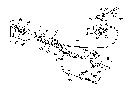
Figure 1 is a diagramatic perspective view (not toscale) of a combined hand and foot control for the
control of a throttle lever on a diesel engine fuel
injection pump;
Figure 2 shows part of the hand control of figure 1 in
more detail;
Figures 3 and 4 show parts of a combining device which
forms part of the control arrangement of ~igure 1, and
Figures 5 and 6 show the combining device in different
states.

1279236
Referring to Figure 1 this shows a combined hand and foot
control arrangement for a throttle member in the form of a
throttle lever 1~ of the tractor diesel engine fuel
injecti~n pump ll. The control arrangement includes a hand
control lever 12 and a throttle pedal 13 which are both
connected with a combining device 14 via Bowden cables 15
and 16 respectively. The combining device is in turn itself
connected by a further Bowden cable 17 with the throttle
lever 10.
The hand control lever 12 is supported on a shaft 12a for
pivotting about an axis A-A by a lower bracket lB and an
upper bearing support l9 provided as part of the vehicle
instrument panel. The end 15a of the inner of Bowden cable
15 is connected with an arm 20 which is supported from a
boss 21 on the lower end of shaft 12a. As is conventional
with such hand controls a friction device is provided to
hold the hand lever in the position set by the tractor
operator. This can conveniently be provided by the
arrangement shown in Figure 2 in which friction material
22 on the bottom of boss 21 is clamped against support
bracket 18 by a compression spring 23 which is held captive
on the lower end of shaft 12a by a washer 24 and nut 25.
The throttle pedal 13 is mounted for pivoting about an axis
~.'`

127~2~6
B-B just helow the tractor cab floor or footstep, part of
which is shown at 26. The pedal is provided with a stop 27
which abuts the underside of floor 26 to limit the d~wnward
movement of pedal 13. The end 16a of the inner of Bowden
cable 16 is connected with pedal 13 via an arm 28 and a
spring 29 acts between the arm 28 and a fixed point 3~ on
the tractor to maintain the Bowden cable end 16a tensioned
and also to prevent vibration of the throttle pedal
arranqement.
The combining ~evice 14 comprises two housing halves 14a and
14b of plastics material which are bolted together at 31.
These bolts 31 also serve to secure the combining device to
a support bracket 32 w~ich is mounted on any convenient part
of the tractor. Figure 3 shows the internal details of the
combining device with the upper part 14a removed. Within
the two housing halves a channel 33 is defined in which a
combining member 34 in the form of a plastics block is
slidable. This block is shown in greater detail in Pigure
4. The block includes three longitudinally extending slots
35, 36 and 37 which are arranged to receive the ends 15b,
16b, 17b of the inners Bowden cables 15, 16 and 17
respectively.
As can be seen from Figure 3 the nipples 15c and 16c of
cables 15 and 16 are partially recieved in recesses 35a and
36a provided in block 34. Similarly the nipple 17c of c~ble
17 is received in a corresponding recess in the opposite end
of bloc~ 34. The outers of cables 15, 16 and 17 are held
captive within the housing halves by engagement of end
ferrules 15d, 16d and 17d in recesses 14c and 14d in the
housing halves.
Figure 3 shows the combininq member 34 in its minimum or
idling speed position corresponding to the position of the
hand control 12 and pedal 13 of Figure 1. In this position

1279236
the throttle lever is biased by spring 38 into its closed or
id~e position shown in Figure 1.
If we now assume that the tractor operator moves the hand
lever 12 in the direction X of Figure 1 to position 12' this
will increase the engine speed by drawing the inner of cable
15 to the right as viewed in Figure 5 to draw the block 34
to the position 34' shown in Pi~ure 5. This in turn draws
the inner of cable 17 to the right thus pivotting the
throttle lever 10 to the Aotted line position 10' shown in
Figure 1. Because of the action of spring 29 the inner of
cable 16 is also drawn to the right so that the nipple 16c
maintains contact with the recess 36a as shown in Figure 5
and the pedal 13 thus pivots to the depressed position 13'.
If the operator now decides to override set the throttle
lever position 10' by further depressing the pedal to the
position 13" this will draw the inner of cable 16 to the
right, as viewed in Figure 6, thus drawing the block 34 to
position 34" and pivoting the throttle lever to position 10"
via cable 17. As can be seen from Figure 6, when the block
moves to position 34" the end 15b of the inner of cable 15
does not move since the hand control 12 is held stationary
by the friction device associated with the hand control.
Thus block 34 slides relative the cable end 15b.
lf the operator then lifts his foot from pedal 13, the pedal
will rise to position 13' and the block will return to
position 34' under the action of spring 38 which also
returns the throttle lever to position 10', thus returning
the throttle lever to the position set by the hand lever 12.
As will be appreciated the present invention therefore
provides a simple, low cost and efficient arrangement for
comhininq hand anA foot throttle controls which, due to its
use of flexible Bowden cables, is particularly easy to

~ 12792~36
instal on a variety of different machines, since the cables
can easily be routed to the throttle lever from the hand and
foot controls by the most convenient route.

Dessin représentatif
Une figure unique qui représente un dessin illustrant l'invention.
États administratifs

2024-08-01 : Dans le cadre de la transition vers les Brevets de nouvelle génération (BNG), la base de données sur les brevets canadiens (BDBC) contient désormais un Historique d'événement plus détaillé, qui reproduit le Journal des événements de notre nouvelle solution interne.

Veuillez noter que les événements débutant par « Inactive : » se réfèrent à des événements qui ne sont plus utilisés dans notre nouvelle solution interne.

Pour une meilleure compréhension de l'état de la demande ou brevet qui figure sur cette page, la rubrique Mise en garde , et les descriptions de Brevet , Historique d'événement , Taxes périodiques et Historique des paiements devraient être consultées.

Historique d'événement

Description Date
Inactive : CIB de MCD 2006-03-11
Le délai pour l'annulation est expiré 2005-01-24
Lettre envoyée 2004-01-22
Inactive : TME en retard traitée 2002-02-13
Lettre envoyée 2002-01-22
Lettre envoyée 2000-10-02
Accordé par délivrance 1991-01-22

Historique d'abandonnement

Il n'y a pas d'historique d'abandonnement

Historique des taxes

Type de taxes Anniversaire Échéance Date payée
Enregistrement d'un document 1997-09-25
TM (catégorie 1, 7e anniv.) - générale 1998-01-22 1997-12-10
TM (catégorie 1, 8e anniv.) - générale 1999-01-22 1998-12-14
TM (catégorie 1, 9e anniv.) - générale 2000-01-24 1999-12-15
TM (catégorie 1, 10e anniv.) - générale 2001-01-22 2000-12-14
TM (catégorie 1, 11e anniv.) - générale 2002-01-22 2002-02-13
Annulation de la péremption réputée 2002-01-22 2002-02-13
TM (catégorie 1, 12e anniv.) - générale 2003-01-22 2003-01-22
Titulaires au dossier

Les titulaires actuels et antérieures au dossier sont affichés en ordre alphabétique.

Titulaires actuels au dossier
AGCO LIMITED
Titulaires antérieures au dossier
HARRY SUMMERS
JOHN LESLIE OLD
Les propriétaires antérieurs qui ne figurent pas dans la liste des « Propriétaires au dossier » apparaîtront dans d'autres documents au dossier.
Documents

Pour visionner les fichiers sélectionnés, entrer le code reCAPTCHA :


Pour visualiser une image, cliquer sur un lien dans la colonne description du document (Temporairement non-disponible). Pour télécharger l'image (les images), cliquer l'une ou plusieurs cases à cocher dans la première colonne et ensuite cliquer sur le bouton "Télécharger sélection en format PDF (archive Zip)" ou le bouton "Télécharger sélection (en un fichier PDF fusionné)".

Liste des documents de brevet publiés et non publiés sur la BDBC .

Si vous avez des difficultés à accéder au contenu, veuillez communiquer avec le Centre de services à la clientèle au 1-866-997-1936, ou envoyer un courriel au Centre de service à la clientèle de l'OPIC.

({010=Tous les documents, 020=Au moment du dépôt, 030=Au moment de la mise à la disponibilité du public, 040=À la délivrance, 050=Examen, 060=Correspondance reçue, 070=Divers, 080=Correspondance envoyée, 090=Paiement})


Description du
Document 
Date
(aaaa-mm-jj) 
Nombre de pages   Taille de l'image (Ko) 
Revendications 1993-10-17 2 54
Abrégé 1993-10-17 1 29
Dessins 1993-10-17 2 39
Description 1993-10-17 7 205
Dessin représentatif 2001-10-31 1 13
Avis concernant la taxe de maintien 2002-02-18 1 179
Quittance d'un paiement en retard 2002-02-25 1 172
Avis concernant la taxe de maintien 2004-03-17 1 173
Taxes 2003-01-21 1 33
Taxes 1995-12-13 1 47
Taxes 1996-12-11 1 98
Taxes 1994-12-13 1 95
Taxes 1994-01-23 1 33
Taxes 1993-01-19 1 31