Note : Les descriptions sont présentées dans la langue officielle dans laquelle elles ont été soumises.
3~
~ 7. .
1 BACKGROUND OF THE INVENTION
The present invention xelates to a liquid-gas
contactor for use with a non-azeotropic mixture refrig-
erant.
Fig. 2 shows an example of a refrigeration
cycle which makes usè of a non-azeotropic mixture
refrigerant composed of two or more refrigerants such
as, for example, R13Bl and R22. Fig. 3 shows the con-
struction of a gas-liquid contactor which is used for
changing the mixing ratio of the refrigerants in the
non-a~eotropic mixture refrigerant.
Referring to ~i~. 2, the refrigeration cycle
includes a compressor 1, a condenser 2, a first orifice
means 3, a second orifice means 4, an evaporator 5, a
gas-liquid contactox 6, a cooler 7, and a reservoir 8.
Referring now to Fig. 3, the gas-liquid con-
tactor 6 has a container 9, a connection pipe 10 through
which the container 9 is connected to the upstream side
of the gas-liquid contactor 6 in the refrigeration
cycle, a connection pipe 11 through which the container
9 is connected to the downstream side of the gas-liquid
contactor in the refrigeration cycle, lower and upper
filler holders 12, 13, filler 14, a gas outlet pipe 15,
and a liquid return pipe 16 leading from the reservoir
8.
l In operation of the refrigeration cycle shown
in Fig. 2, the mixture refrigerant compressed and
discharged from the compressor l is recirculated as
indicated by an arrow and is returned to the compressor
l. During recirculation, the refrigerant discharged
from the compressor 1 is condensed and liquefied in the
condenser 2 and the condensate of the refrigerant is
expanded through the first orifice device 3 so that a
part of the mixture refrigerant is evaporated. The
gaseous phase of the refrigerant generated in the first
orifice device 3 is introduced through the connection
pipe lO to the gas-liquid contactor 6 and ascends
through the tiny spaces formed in the bed of the filler
14 so as to flow through the gas outlet pipe 15 into
the cooler 7 where it is cooled and liquefied again to
flow into the reservoir 8.
A portion of the liquid phase of the refrig-
erant is rèturned from the reservoir 8 to the gas-liquid
contactor 6 through the liquid return pipe 16 and flows
down through the tiny spaces in the bed of filler 14
so as to contact with the gaseous phase of the refrig-
erant flowing upward through these spaces. As a result,
heat is exchanged between the liquid and gaseous phases
of the refrigerant, whereby the mixing ratio of the
recirculated refrigerant is changed.
Thus, the mixing ratio of the mixture refrig-
erant recirculated through the refrigeration cycle is
varied by the gas-liquid contactor~ The range of
-- 2 --
1 variatlon of the mixing ratio is ruled by the perform-
ance of the gas-liquid contactor 6. More specifically,
the range over which the mixing ratio is changed is
increased by promoting the heat exchange through attain-
ing a greater chance of contact between the liquid andgaseous phases of the refrigerant. This can be achieved
by increasing the area of contact between two phases of
the refrigerant. It is therefore desirable that the
gas-liquid contactor is designed to invite a greater
quantity of gaseous phase of the refrigerant.
The construction of the gas-liquid contactor
6 shown in Fig. 3 suffers from a problem in that, since
the position of the liquid returning pipe 16 leading
from the reservoir 8 is offset from the center of the
container 9, a local concentration of the liquid phase
of the refrigerant tends to occur through the filler
bed. This hampers uniform distribution of the liquid
phase, with the result that the gas-liquid contact
cannot be conducted uniformly over the entire region of
the filler bed.
In addition, since the lower filler holder 12
is so designed as to extend perpendicularly to the
direction o flow of the gaseous phase of the refrigerant
introduced through the connection pipe 10 leading rom
an upstxeam portion of the refrigeration cycle, the
lower filler holder 12 poses a large resistance against
the gaseous phase of the refrigerant entering the bed
of the filler 14 through the holes in the lower filler
; ' `. ...
gL~
holder 12. In consequence, a considerable portion of the gaseous
phase of the refrigerant introduced through the connection pipe
10 is made to flow directly to the downstream side of the gas-
liquid contactor in the refrigeration cycle through the
connection pipe 11, without entering the bed of -the filler. In
consequence, the area of the gas-liquid contact is decreased to
reduce the range of variation of the mixing ratio.
SUMMARY OF THE INVENTION
Accordingly the present invention provides an improved
gas-liquid contactor for use in a refrigeration cycle which
operates with non-azeotropic mixture refrigerant, which is
capable of widening the range over which the mixing ratio of
recirculated refrigerant is variable.
According to the present invention, there is providecl a
gas-liquid contactor for vary~ing the mixing ratio of a non-
azeotropic refrigerant circulated through a refrigeration cycle,
wh~rein the liquid returning pipe has a lower end which is opened
downward in-to the container of -the gas-liquid contactor at a
position substantially on the axis of the container, so that the
returned liquid refrigerant can be uniformly distributed over the
entire region of the filler bed so as to enhance exchange of heat
between the gaseous phase and the liquid phase of the
refrigerant.
In a preferred form of the invention, the lower filler
holder is convexed upward substantially at its central portion
towards the filler so as to smoothly guide the gaseous phase of
the refrigerant into the bed o~ the filler.
Features and advantages of the invention will become
clear from the following description of the preferred embodiments
when the same is read in con~unction with the accompanying
drawings in which:
-- 4 --
~7~
Fig. l is a sectional view of a gas-liquid contactor
embodying the present invention;
Fig. 2 is a diagram of a refrigeration cycle which
incorporates the gas-liquid contactor of the present invention;
and
Fig. 3 is a sectional view of a known gas-liquid
contactor.
FigO l shows an embodiment of the gas-liquid contactor
of the invention, while Fig. 2 shows a refrigeration cycle
incorporating the gas-liquid contactor.
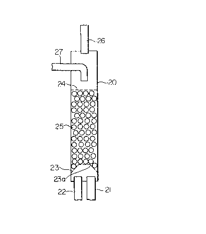
Referring to Fig. 2, the gas-liquid contactor embodying
the present invention has a container 20, a connection pipe 21
through which the container ~0 is connected to the upstream side
of the gas-liquid contactor in the refrigeration cycle, a
connection pipe
`
''-
' ~ .'
.
. .
~ 3~ ~
22 through which the container 20 is connected to the downstream
side of the gas-contactor in the refrlgerat:Lon cycle, lower and
upper filler holders 23, 2~ having a multlplicity of apertures, a
bed of filler 25 completely filling the space between the lower
and upper filler holders 23, 24, a gas outlet plpe 26, and a
liquid returning pipe 27 leading from the reservoir and extended
into the container 20 through an upper portion of the side wall
of the container 20. The lower end of -the liquid returning pipe
27 is bent such that the lower end opening therof is located
substantially on the axis of the container 20 such as to open
downward. The lower filler holder 23 is convexed upward at its
central portion as denoted by 23a.
In operation, the refrigerant condensed in the condenser 2 of the
refrigeration cycle and now in liquid phase is expanded through
the first orifice device 3 so that a part of the refirgerant is
evaporated into gaseous phase. A part of a refrigerant mixture
which is a part of a refrigerant having a lower boiling point and
which has been turned into steam is introduced into the gas-
~0 liquid contactor 6 through the upstream connection pipe 21. A
part of the mixed refrigerant which has not yet been turned into
steam, that is, which is composed of a part of the above-
mentioned refrigerant that has not yet been turned into steam and
a refrigerant having a high boiling point flows directly into the
downstream connection pipe 22 in liquid form wlthout making
contact with the filer 25 in the gas-liquid contactor 6. The
gaseous phase of refrigerant thus formed is introduced into the
B
~ ~7~
gas-liquid contactor 6 through the connecting pipe 21 and ascends
through tiny spaces in the bed of the filler 25. The gaseous
phase of the refrigerant then flows ~hrough the gas outlet pipe
26 into the cooler 7 where it is cooled to become liquid
refrigerant which is then reserved in the reservoir 8.
portion of the liquid refrigerant in the reservoir 8 is
returned through the liquid returning
- 6a ~
.
.. ~ .
1 pipe 27 into the gas-liquid contactor 6 and flows
downward through the tiny spaces in the bed of the filler
25 so as to make gas-liquid contact with the gaseous
phase flowing upward through the same tiny spaces,
thereby varying the mixing ratio of the recirculated
refrigerant through heat exchange and transition of
substance.
The refrigerant with varied mixing ratio is
then introduced through the connecting pipe 22 into
the second orifice device 4 so as to be expanded through
the latter and then flows into the evaporator 5.
The liquid returning pipe 27 leading from the
reservoir 8 may be extended into the container 20
through the top end of the container 20 provided that
the diameter of the container 20 is sufficiently small.
Since the lower end of the liquid returning pipe 27 is
opened downward at a position which is substantially on
the axis of the container 20, the returning liquid can
flow through the filler 25 with reduced tendency of
local concentration, so that the gas-liquid contact can
be effected over the entire region of the bed of the
filler 25, thus enlarging the area of the gas-liquid
contact.
In addition, since the central portion of the
lower filler holder 23 is convexed upward as denoted
by 23a towards the filler 25, the lower filler holder
23 produced only a small resistance against the flow of
the gaseous refrigerant intxoduced into the gas-liquid
-- 7 --
1 contactor 6. As a result, a yreater portion of the
gaseous phase of refrigerant introduced into the gas-
liquid contactor 6 is allowed to flow into the bed of
the filler 25, so as to increase the area of the gas-
liquid contact thereby enhancing the heat exchangebetween both phases of the refrigerant. As a result,
the performance of the filler is fully utilized so as
to widen the range of variation of the mixing ratio.
In consequence, a large heat-exchanging
capacity is produced by the combination of the
arrangement of the downward opening of the liquid
returning pipe 27 and the upward convexity of the
central portion of the lower filler holder 23, so as to
enable the mixing ratio to be varied over a wide range.
As has been described, according to the
present invention, the liquid phase of the refrigerant
returned to the gas-liquid contactor can be uniformly
distributed over the entire region of the bed of the
filler so that the effective area for the gas-liquid
contact is enlarged to enable the mixing ratio to be
varied over a wide range. In addition, the permeation
of the gaseous phase of the refrigerant into the bed of
the filler is enhanced so as to increase the area of
the gas-liquid contact, contributing to the widening of
the range of variation of the mixing ratio.
: . :
.
: . ' ' ~ ' . -
'