Sélection de la langue

Search

Sommaire du brevet 1281390 

Énoncé de désistement de responsabilité concernant l'information provenant de tiers

Une partie des informations de ce site Web a été fournie par des sources externes. Le gouvernement du Canada n'assume aucune responsabilité concernant la précision, l'actualité ou la fiabilité des informations fournies par les sources externes. Les utilisateurs qui désirent employer cette information devraient consulter directement la source des informations. Le contenu fourni par les sources externes n'est pas assujetti aux exigences sur les langues officielles, la protection des renseignements personnels et l'accessibilité.

Disponibilité de l'Abrégé et des Revendications

L'apparition de différences dans le texte et l'image des Revendications et de l'Abrégé dépend du moment auquel le document est publié. Les textes des Revendications et de l'Abrégé sont affichés :

  • lorsque la demande peut être examinée par le public;
  • lorsque le brevet est émis (délivrance).
(12) Brevet: (11) CA 1281390
(21) Numéro de la demande: 1281390
(54) Titre français: CONNECTEUR A LOQUET
(54) Titre anglais: LATCH CONNECTOR
Statut: Périmé et au-delà du délai pour l’annulation
Données bibliographiques
(51) Classification internationale des brevets (CIB):
  • H01R 13/633 (2006.01)
  • H01R 13/629 (2006.01)
(72) Inventeurs :
  • PADDOCK, ALBERT W. (Etats-Unis d'Amérique)
(73) Titulaires :
(71) Demandeurs :
(74) Agent: KALEVI P. ASPILAASPILA, KALEVI P.
(74) Co-agent:
(45) Délivré: 1991-03-12
(22) Date de dépôt: 1987-09-17
Licence disponible: S.O.
Cédé au domaine public: S.O.
(25) Langue des documents déposés: Anglais

Traité de coopération en matière de brevets (PCT): Non

(30) Données de priorité de la demande:
Numéro de la demande Pays / territoire Date
933,430 (Etats-Unis d'Amérique) 1986-11-21

Abrégés

Abrégé anglais


ABSTRACT OF THE DISCLOSURE
A latch connector for releasably connecting a male
connector provided with plural male terminals and a female
connector provided with plural female terminals. The connector
includes a handle member cooperating with the latch member to
effect disconnection of a pair of electrical connectors.

Revendications

Note : Les revendications sont présentées dans la langue officielle dans laquelle elles ont été soumises.


THE EMBODIMENTS OF THE INVENTION IN WHICH AN EXCLUSIVE
PROPERTY OR PRIVILEGE IS CLAIMED ARE DEFINED AS FOLLOWS:
1. A latch connector for releasably securing a pair of
electrical connectors together comprising:
a. a latch connector body including a base portion
having holes therein for receiving pin conductors of a first of
said pair of connectors therethrough;
b. a pair of upstanding end latch portions extending
from said base portion and having hook portions at the distal ends
thereof for engagement with the second of said pair of connectors
for retention of said connectors in secured relation;
c. said end latch portions having a groove
therethrough extending from said base portion and terminating
intermediate said base portion and said hook portion, and, an
angled circular opening extending transversely through said end
latch portions and in communication with said groove; and
d. unlatching means disposed in said angled circular
openings and cooperating with said upstanding end members to
effect disconnection of said latch connector from said electrical
connectors, by flexing said end members for release of said hook
portions from said second of said pair of connectors.
2. A device as in claim 1 wherein said unlatching means
includes a handle member having an end portion in the shape of a
ball and a shaft portion extending therefrom said ball disposed in
said circular portion for movement down said groove to provide for
flexing of said end latch portion and release of said hook

portions from said second pair of connectors responsive to
application of a pulling force on said handle portion of said
unlatching means.
3. A device as in claim 2 wherein said latch connector and
said handle member is plastic.

Description

Note : Les descriptions sont présentées dans la langue officielle dans laquelle elles ont été soumises.

3~
This invention relat-es to multi~terminal electrical
connectors.
Electrical connectors oE the type in que~tion typically
consist of a small connector having a plurality of male terminals
diqposed for insertion into a plurality of female terminals of a
female connector. In some cases the frictional engagement between
the male and female connector~ are relied upon for maintaining
secured relation of ~he connector~3. Thls has proverl to be
unsatisEactory when the connectors are uAed in environments where
shock, vibration, or acceleration could cause them to separate, as
in a missile system. Other types of connectors include a lever
mechanism built into the male coupling at opposite ends thereof
and engageable with inden~ations built into ~he ~urface of the
female mamber for retention of the male and female members in
secured relation. Such connectors necessarily require complicated
manufacturing processes in that the lever mechanism must be built
into the male connector at manufacture as must the indentations of
the female connector.
According to the present invention there is provided a
latch connector for releasably securing a pair of electrical
connector~ together comprising: a latch connector body including
a base portion having holes therein for receiving pin conductors
of a first of the pair of connec~ors therethrough: a pair of
upstanding end latch portions extending from the base portion and
having hook portions at the distal ends ~hereof for engagement
with the second of the pair of connectorq for retention of the
connectors in secueed relation; the end latch portions having a
groove therethrough extending from the base portion and terminating
~`7,~

intermediate the ba~e portion and the hoolc portion, and, an angled
circular opening extending tran~versely through the end latch
portions and in communication with the groove; and unlatching
means disposed in the angled circular openings and cooperating
with the upstanding end members to effect disconnection of the
latch connector fFOm the electrical connector~, by flexing the end
member~ for release of the hook portions from the second of the
pair o connector~.
The latch connector may be used a~ an adjunct as~embly
for standard connectors, thus eliminating the need for the latch
connec~or to be made a part of the male or female connectors
during manufacture thereofq
In the accompanying drawing~, which illustrate an
exemplary emb~diment of the pre~ent invention:
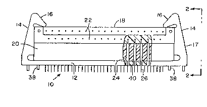
Figure 1 iB an elevational partial sectional view of the
latch connector di~posed for retention of male and female
electrical connectorY in secured relation:
Figure 2 is an end elevational view taken along line 2-2
of Figure 1:
Figure 3 is a sectional view taken along line 3 3 of
Figure 2 with the unlatching handle omitted for clarity: and
Figure3 4, 5 and 6 are elevational view, partially in
~ection, graphically illu~trating the latch connector of the
presen~ invention, respectively, in unmated, mating/unmating, and
latched posi~ions.
As seen in Figure 1 a latch connector assembly 10
include~ a base portion 12 having a pair of upwardly extending
latch portions 14 terminatiny in a pair of latch hooks 16 in

engagement with a male electrical connector 18 for maincaining a
secured relation between the male connector and a emale
electrical connector 20~ The connectors are standard electrical
connectors and the male connector~ include extending pin
conductors 22 and the female connector include~ receptacles 24
having pin conductor~ 26 extending therefrom~
As seen in Figure~ 2 and 3 the upwardly extending
portion 14 of the latch is provided with a groove 28 extending
upwardly from base portion 12 ancl terminating between the hook
portion 16 and base portion 12. The outer surface 17 of portion
14 i8 angled inwardly from the base to the hook portion. An
angled circular opening 30 i8 provided at the upper end 29 of
groove 28. A handle 32 which includes a shaft portion 34 and ball
ends 36 (Figures 4, 5 and 6) i~ positioned in groove 28 and
circular opening 30 to provide for release of the latch member ~o
that the connector bodies can be separated. soth the latch and
the handle consists of molded plastic.
In operation the latch assembly 10 i9 attached to the
connector u~ing the conector mounting rivets 38 with the pins 26
of the bottom connector (female)~20 extending through mating
openings 40 in the base portion 12 of the latch~ A ball end 36 of
handle 32 is inserted in opening 30 and groo~e 28 of latch portion
14 prior to mating the base portion 12 to connector body 20~ A~
the connectorq 18 and 20 are mated, the latch hook portions 16
cam~ on the connector body 18, flex outwardly (because of the
resiliency of portion 14) and then snap into engagement with the
upper surface of tha connector 18. (Figure 6).
Unmating the connectors i~ accomplished (~igures 4 and
-- 3 --

~ Z,~ 9()
5) by pulling on handle 32, causing it~ ball end 36 to cam on the
connector and on the latch groo~es 28 forcing the upwardly
extending latch portion~ 14 away from the connector bodies to flex
the hook portion~ 16 away from the upper connector.
-- 4 --

Dessin représentatif
Une figure unique qui représente un dessin illustrant l'invention.
États administratifs

2024-08-01 : Dans le cadre de la transition vers les Brevets de nouvelle génération (BNG), la base de données sur les brevets canadiens (BDBC) contient désormais un Historique d'événement plus détaillé, qui reproduit le Journal des événements de notre nouvelle solution interne.

Veuillez noter que les événements débutant par « Inactive : » se réfèrent à des événements qui ne sont plus utilisés dans notre nouvelle solution interne.

Pour une meilleure compréhension de l'état de la demande ou brevet qui figure sur cette page, la rubrique Mise en garde , et les descriptions de Brevet , Historique d'événement , Taxes périodiques et Historique des paiements devraient être consultées.

Historique d'événement

Description Date
Inactive : CIB de MCD 2006-03-11
Inactive : Demande ad hoc documentée 1994-03-12
Le délai pour l'annulation est expiré 1993-09-14
Lettre envoyée 1993-03-12
Accordé par délivrance 1991-03-12

Historique d'abandonnement

Il n'y a pas d'historique d'abandonnement

Titulaires au dossier

Les titulaires actuels et antérieures au dossier sont affichés en ordre alphabétique.

Titulaires actuels au dossier
S.O.
Titulaires antérieures au dossier
ALBERT W. PADDOCK
Les propriétaires antérieurs qui ne figurent pas dans la liste des « Propriétaires au dossier » apparaîtront dans d'autres documents au dossier.
Documents

Pour visionner les fichiers sélectionnés, entrer le code reCAPTCHA :


Pour visualiser une image, cliquer sur un lien dans la colonne description du document. Pour télécharger l'image (les images), cliquer l'une ou plusieurs cases à cocher dans la première colonne et ensuite cliquer sur le bouton "Télécharger sélection en format PDF (archive Zip)" ou le bouton "Télécharger sélection (en un fichier PDF fusionné)".

Liste des documents de brevet publiés et non publiés sur la BDBC .

Si vous avez des difficultés à accéder au contenu, veuillez communiquer avec le Centre de services à la clientèle au 1-866-997-1936, ou envoyer un courriel au Centre de service à la clientèle de l'OPIC.


Description du
Document 
Date
(aaaa-mm-jj) 
Nombre de pages   Taille de l'image (Ko) 
Dessins 1993-10-18 2 35
Revendications 1993-10-18 2 42
Abrégé 1993-10-18 1 10
Description 1993-10-18 4 116
Dessin représentatif 2000-07-05 1 9