Sélection de la langue

Search

Sommaire du brevet 1284031 

Énoncé de désistement de responsabilité concernant l'information provenant de tiers

Une partie des informations de ce site Web a été fournie par des sources externes. Le gouvernement du Canada n'assume aucune responsabilité concernant la précision, l'actualité ou la fiabilité des informations fournies par les sources externes. Les utilisateurs qui désirent employer cette information devraient consulter directement la source des informations. Le contenu fourni par les sources externes n'est pas assujetti aux exigences sur les langues officielles, la protection des renseignements personnels et l'accessibilité.

Disponibilité de l'Abrégé et des Revendications

L'apparition de différences dans le texte et l'image des Revendications et de l'Abrégé dépend du moment auquel le document est publié. Les textes des Revendications et de l'Abrégé sont affichés :

  • lorsque la demande peut être examinée par le public;
  • lorsque le brevet est émis (délivrance).
(12) Brevet: (11) CA 1284031
(21) Numéro de la demande: 1284031
(54) Titre français: REGULATEUR DE GARDE AU SOL POUR TONDEUSE
(54) Titre anglais: HEIGHT ADJUSTER FOR LAWNMOWERS
Statut: Périmé et au-delà du délai pour l’annulation
Données bibliographiques
(51) Classification internationale des brevets (CIB):
  • A01D 34/74 (2006.01)
(72) Inventeurs :
  • EILLES, FRANK A. (Canada)
(73) Titulaires :
  • BRIGGS & STRATTON CANADA INC.
(71) Demandeurs :
  • BRIGGS & STRATTON CANADA INC. (Canada)
(74) Agent: SMART & BIGGAR LP
(74) Co-agent:
(45) Délivré: 1991-05-14
(22) Date de dépôt: 1989-09-11
Licence disponible: S.O.
Cédé au domaine public: S.O.
(25) Langue des documents déposés: Anglais

Traité de coopération en matière de brevets (PCT): Non

(30) Données de priorité de la demande:
Numéro de la demande Pays / territoire Date
(279,164) (Etats-Unis d'Amérique) 1988-12-02

Abrégés

Abrégé anglais


ABSTRACT OF THE DISCLOSURE
HEIGHT ADJUSTER FOR LAWNMOWERS
A lawnmower has a series of openings in the housing into which
wheel axles may be selectively engaged to adjust the cutting height. The axis
ends are grooved, and the housing provided with a slot into which a clip is
insertible to coact with the groove and retain the axle in position.

Revendications

Note : Les revendications sont présentées dans la langue officielle dans laquelle elles ont été soumises.


THE EMBODIMENTS OF THE INVENTION IN WHICH AN EXCLUSIVE PROPERTY
OR PRIVILEGE IS CLAIMED ARE DEFINED AS FOLLOWS:
1. In a lawnmower including a housing; wheels and wheel axles for
supporting said housing from a ground surface; said housing having a series of
vertically spaced apart bores therein associated with each said wheel for
selectively engaging a wheel axle therein for varying the clearance of the
housing from the ground surface, each said axle having adjacent the proximal end
thereof a peripheral groove, the improvement wherein said lawnmower comprises;
guide means on said housing associated with each series of bores, said guide
means comprising a slotted passageway, each said bore of an associated series of
bores being completely intersected by said passageway, and blade means having a
plurality of transversely aligned corrugations therealong slidable along each said
slotted passageway, said blade means having an elongated opening to engage said
peripheral groove therein to secure a said axle in a selected bore, with
corrugated portions of said blade means in interfering relationship with said
guide means along the length thereof.
2. A lawnmower as defined in Claim 1, wherein one of said blade
means and said guide means is provided with a stop to limit travel of said blade
in said groove, and said corrugations are arranged such that when said blade is
positioned at its travel limit, a peak of a said corrugation remote from said
wheel is in horizontal alignment with the axis of each said bore.
3. A lawnmower as defined in Claim 1, wherein said blade includes an
upper, handle portion forming said stop, and a lower dagger portion, and wherein
said handle portion is inclined relative to said dagger portion.
4. A lawnmower as defined in Claim 1, wherein said corrugations
extend across the width of said blade means.

5. A lawnmower as defined in Claim 4, wherein said lower blade
portion is a spring tempered sheet steel.
6. In a lawnmower including a housing; wheels and wheel axles for
supporting said housing from a ground surface; said housing having a series of
spaced apart bores therein associated with each wheel for selectively engaging a
wheel axle therein for varying the clearance of the housing from the ground
surface, the improvement wherein each said axle is provided adjacent the
proximal end thereof with a peripheral groove, and wherein said lawnmower
comprises; guide means on said housing adjacent each series of bores, said guide
means having at least one surface undulation therealong, and blade means
slidable along each said guide means, said blade means having a transversely
corrugated free edge to engage said peripheral groove to secure a said axle in a
selected bore, one of said blade means and said guide means being provided with
a stop to limit travel of said blade means along said guide means such that when
said blade means is positioned at its travel limit a peak of said corrugation
remote from said wheel is in horizontal alignment with the axis of each said
bore, and at least one peak of said corrugation is in cooperative alignment with
said undulation.
'1
Patent Agent
Toronto, Ontario.

Description

Note : Les descriptions sont présentées dans la langue officielle dans laquelle elles ont été soumises.

~L284~)3~
HEIGHT ADJUSTER FOR LAWNMOWERS
This invention relates to lawnmowers. It particularly relates to a
sirnple height adjusting means.
In a lawnmower particular of the rotary blade type which includes
a housing and wheels journalled on axles mounted from the housing For supporting
5 the housing from a ground surface, the most simple height adjustment means is
formed by providing a series of bores in the housing into which the axles may be
selectively inserted and secured. Securement is usually by way of a nut which
connects to the proximal, threaded end of the axle, and adjustment of cutting
height as a consequence involves the use of a wrench, and inverting the
10 lawnmower thereby exposing the cutting blade and creating a potential hazard.
While other sophisticated height adjustment mechanisms are known
and are in commercial use, they usually involve additional expense, and are
therefore not used on low price, no frills lawnmowers.
It is an object of this invention to provide in a lawnmower a
15 simple, cheap and reliable height adjustment means.
It is a further object of the invention to provide such a means
which does not require the inversion of the lawnmower.
.

~8~)31
-- 2 --
In accordance with one object of the Invention, this comprises
provlding in a lawnmower haviny a serleS of bores into which a wheel axle may
be selectively engaged, a peripheral groove in the proximal end of the axle. Thehousing is provided with guide rneans associated with each series of bores, and
blade means slidable along the guide means. The blade means is provided with a
free edge that engages the peripheral groove to thereby retain the axle in any
selected bore.
Preferably the free edge is transversely corrugated, whereby the
peaks of the corrugation will move into interfering position with the groove in a
manner to urge the axle inwardly in the bore. Suitably the blade means will
include a stop to limit the travel of the blade means in the guide means, at
which limit a blade corrugation will be in interfering position with the axle.
Desirably the guide means will be provided with one or more surface portions
that will be in cooperating engagement with corrugations on the blade means
when it reaches its travel limit, to assist in retaining the blade means in its
inserted position in the guide means.
Suitably the blade means is in the form o-F a clip comprising a
transversely corrugated steel strip formed with a slot therelong, the edges of the
strip defining the slot forming two free edges which coact with the peripheral
groove on the axle on diametrically opposed sides thereof. In accordance with
the preferred embodiment the slot is open at the lower end thereof to permit theclip to be fully disengaged from the guide means, although it is contemplated
that a keyhole arrangement could be provided and the clip retained captive in
the guide means.
This foregoing objects and aspects of the invention, together with
other objects, aspects and advantages thereof will be more apparent from the

~28~031
following description of a preferred embodiment thereof, taken in conjunction
with the foregoing drawings, wherein
FIG. 1 - shows a lawnmower of a type in which the
invention may be embodied;
FIG. 2 - shows a partial view of one corner of a
Iawnmower housing adapted for use with the
present invention;
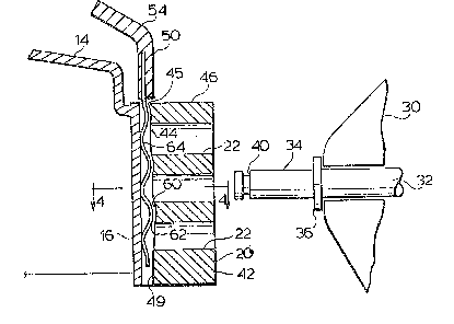
FIG. 3 - shows a section along 3-3 of Fig. 2, together
with a portion of a wheel and axle in position
for engagement in the housing, with an axle
retaining clip in its engaged position;
FIG. 4 - is a section along 4-4 of Fig. 3, with the axle in
engaged position and the clip withdrawn, and
FIG. 5 - is a perspective view of the clip of the
invention.
Considering the drawings in detail, a lawnmower is shown generally
in Fig. 1 wherein it is identified by the numeral 10.
Lawnmower 10 includes a housing 12 including a deck portion 14
and skirt wall 16 depending downwardly therefrom. Adjacent the corners of the
deck, the skirt is extended outwardly tc form a rectangular prismatic boss 20.
Boss 20 is provided with a plurality of similar horizontally aligned bores 22
therein in vertically spaced apart relationship. As best seen in Fig. 3, a wheel 30
is provided with an axle 32 which includes a shaft end portion 34 separated fromthe axle portion upon which wheel 30 is journalled by a shoulder 36. Shaft end
portion 34 is provided with a peripheral groove 40 therearound. Shaft end portion

lZB~3~
74 has a diameter whereby it will fit snugly into a selected bore 22~ with
shoulder 36 contiguous with the outward -face 42 of boss 20~
Boss 20 is provided with a deep slot 44 having an opening 45 in the
upper end 46 of the boss. Slot 44 extends paraliel to face 42~ and is in part
defined by two parallel channels 47 extending on diametrically opposed sidas of
bores 22~ The rearward plane defined by channels 47 is displaced marginally
rearwardly of the most rearward portions of the plane in which peripheral groove40 resides when axle 32 is manually inserted into a bore 22~ Slot 44 is further
defined by a Forward face 49~ The words "rearward" and "forward" have
particular reference here to Figs 3 and 4 rather than the direction of travel oflawnmower 10.
A clip 50 is provided consisting of a spring tempered steel strip
portion 52 and a handle portion 54~ Clip 50 has an elongated opening forming a
slot 56 therein, the width of which is intermediate the diameter of axle shaft
end 34 and groove 40~ Clip 50 is formed with horizontally aligned, equi-spaced
corrugations 5E~ across the width of strip portion 52~ and is general;y dimensioned
to be an easy friction fit in slot 56~ However, slot 44 is provided with
undulations in forward face 4~ comprising small depressions 60r ~/Vhen clip 50 is
inserted fully into slot 44~ handle portion 54 abuts the upper wall of boss 20 to
form a travel limit for the clip, in which position forward facing crests 62 of the
corrugations nest in surface depressions 60 to assist in retaining the clip in
position. Although shown in Fig. 3 as the crests 62 and depressions 60 being
physically spaced apart, this is for the sake of clarity only9 and these portions
will tend to be in interference.
As earlier indicated, channels 47 generally overlap rearward
portions of the plane in which peripheral axle groove 40 resides. As clip 50 is

~ 03~
urged downwardly in slot 44, rearward facing crests 64 of the corrugations will
Interfere moderately strongly with the rearward wall of groove 40, thereby
urging axle 32 rearwardly, forcing shoulder 36 into firm abutment with face 42
of boss 20. The parts are dimensioned such that rearward facing crests locate inhorizontal planes containing the axes of bores 22 when clip 50 is in its fully
inserted position.
It will be appreciated that if clip 50 as shown In Fig. 3 were
rotated out of the plane of the paper through 180", crests 62 would no longer
coact with depressions 60 and grooves 40 in the desired manner. Clip 50 is
therefore made to be asymmetric, here by handle portion 54 being rearwardly
turned, so as to provide an indication to an operator of the correct orientationof the clip.
It is also contemplated that opening 45 might be configured with
handle portion 54 to Form an asymmetric key-keyway combination, and other
alternative as will equally occur to persons in the art.
It will be apparent that the invention may be embodied In many
different forms some of which may be preferred according to particular
circurnstances and it is intended that all such embodiments should be covered bythe Spilit of the claims appended hereto.

Dessin représentatif
Une figure unique qui représente un dessin illustrant l'invention.
États administratifs

2024-08-01 : Dans le cadre de la transition vers les Brevets de nouvelle génération (BNG), la base de données sur les brevets canadiens (BDBC) contient désormais un Historique d'événement plus détaillé, qui reproduit le Journal des événements de notre nouvelle solution interne.

Veuillez noter que les événements débutant par « Inactive : » se réfèrent à des événements qui ne sont plus utilisés dans notre nouvelle solution interne.

Pour une meilleure compréhension de l'état de la demande ou brevet qui figure sur cette page, la rubrique Mise en garde , et les descriptions de Brevet , Historique d'événement , Taxes périodiques et Historique des paiements devraient être consultées.

Historique d'événement

Description Date
Le délai pour l'annulation est expiré 2007-05-14
Lettre envoyée 2006-05-15
Lettre envoyée 2005-10-18
Lettre envoyée 2001-05-31
Lettre envoyée 2000-12-08
Inactive : TME en retard traitée 1997-07-16
Accordé par délivrance 1991-05-14

Historique d'abandonnement

Il n'y a pas d'historique d'abandonnement

Titulaires au dossier

Les titulaires actuels et antérieures au dossier sont affichés en ordre alphabétique.

Titulaires actuels au dossier
BRIGGS & STRATTON CANADA INC.
Titulaires antérieures au dossier
FRANK A. EILLES
Les propriétaires antérieurs qui ne figurent pas dans la liste des « Propriétaires au dossier » apparaîtront dans d'autres documents au dossier.
Documents

Pour visionner les fichiers sélectionnés, entrer le code reCAPTCHA :


Pour visualiser une image, cliquer sur un lien dans la colonne description du document (Temporairement non-disponible). Pour télécharger l'image (les images), cliquer l'une ou plusieurs cases à cocher dans la première colonne et ensuite cliquer sur le bouton "Télécharger sélection en format PDF (archive Zip)" ou le bouton "Télécharger sélection (en un fichier PDF fusionné)".

Liste des documents de brevet publiés et non publiés sur la BDBC .

Si vous avez des difficultés à accéder au contenu, veuillez communiquer avec le Centre de services à la clientèle au 1-866-997-1936, ou envoyer un courriel au Centre de service à la clientèle de l'OPIC.

({010=Tous les documents, 020=Au moment du dépôt, 030=Au moment de la mise à la disponibilité du public, 040=À la délivrance, 050=Examen, 060=Correspondance reçue, 070=Divers, 080=Correspondance envoyée, 090=Paiement})


Description du
Document 
Date
(aaaa-mm-jj) 
Nombre de pages   Taille de l'image (Ko) 
Dessins 1993-10-19 4 71
Abrégé 1993-10-19 1 9
Revendications 1993-10-19 2 61
Description 1993-10-19 5 141
Dessin représentatif 2000-07-18 1 14
Quittance d'un paiement en retard 1997-07-29 1 172
Courtoisie - Certificat d'enregistrement (document(s) connexe(s)) 2001-05-30 1 113
Courtoisie - Certificat d'enregistrement (document(s) connexe(s)) 2005-10-17 1 106
Avis concernant la taxe de maintien 2006-07-09 1 172
Taxes 2003-05-12 1 30
Taxes 2002-03-04 1 36
Taxes 2004-04-14 1 32
Taxes 1995-05-04 1 35
Taxes 1996-04-08 1 35
Taxes 1994-04-07 1 37
Taxes 1993-05-13 1 27