Note : Les descriptions sont présentées dans la langue officielle dans laquelle elles ont été soumises.
51;~7
Methods for Weld Repairing Hollow, Air
Cooled Turbine Blades and Vanes
Technical Field
This invention relates to methods for welding
metal components. In particular, it relates to
methods for weld repairing superalloy components
used in gas turbine engines.
Background
Hollow, air cooled blades and vanes are commonly
used in modern gas turbine engines. These
components have an internal cavity through which air
flows during engine operation. This air is
discharged through holes, called cooling holes,
which are present in the airfoil section and
sometimes present in the platform and tip. See,
e.g., commonly assigned U.S. Patent No. 4,474,532 to
Pazder. The passage of air through and over the
~; blade or vane extracts heat from the component
surface, allowing use of the component even when the
gas stream temperature exceeds the melting
temperature of the alloy from which it is made.
Some gas turbine engines are designed so that
during engine operation, the tip portion of the
rotating blades rubs a stationary seal, and limits
the leakage of working medium gases in the axial
flow direction. While the seals are usually more
abradable than are the blade tips (so that during
such rub interactions, a groove is cut into the
~;` seal), the blade tips do wear, and the blades become
,~ ~
: : ~: . :: ~:;:
:: : ~
~: : :
`~ ~ , ' ;
~ ~3S~7
shorter. ~s the blades accummulate service time,
the total tip wear increases to the point that
eventually, the efficiency of the blade and seal
system is reduced, and the seal and blades need to
be repaired or replaced.
The tips of worn blades can be repaired, and the
length of the blade increased, by the addition Oe
weld ~iller metal to the tip using any of the
welding techniques (typically arc welding
techniques) known to those skilled in the art.
~uring such a weld repair operation, cooling holes
near the blade tip are susceptible to being welded
shut. These cooling holes must then be redrilled,
e.g., using conventional laser or electrodischarge
machining ~EDM) techniques, before the blade carl be
used again.
However, with some blades used in advanced gas
turbine engines, it is not practical to redrill the
cooling holes after weld repairing the tip. This is
due to the complex geometry of the holes, sometimes
referred to as diffusion or shaped holes. See,
e.y., U.S. Patent Nos. 3,527,543 to Howald and
4,197,443 to Sidenstick. Air discharged through
these holes forms an insulative film over the
surface of the blade during engine operation, which
further protects the blade from the effects of
operating at very high temperatures. Shaped holes
have a nonuniform cross section; for example, the
entrance or metering portion of the hole generally
has a very small diameter (in the range of about
0.010-0.050 cm (0.005-0.020 in.)) while the exit or
i127
diffuser portion of the hole has a relatively large
diameter (in the range of about 0.090-0.115 cm
(0.035-0.045 in.)). Furt:hermore, shaped holes may
have a square cross secti.on at the metering portion
and rectangular cross sec:tion at the diffuser
portion.
~ 9 can therefore be appreciated, the formation
o~ shaped holes can be a di~ficult and technically
complex operation. Consequently, if a blade having
shaped holes is weld repaired, such a repair
operation is preferably done so that the holes are
not welded shut and do not have to be redrilled.
Accordingly, what is needed is a method for wel~d
repairing components having shaped cooling holes so
that the holes are shielded from the molten Eiller
metal and do not need to be redrilled after the weld
; operation.
U.S. Patent No. 3,576,065 to Frazier discloses
one method for weld repairing hollow gas turbine
engine vanes having cooling holes with a constant
diameter of about 0.125 cm (0.050 in.). Prior to
welding, cylindrical ceramic inserts are inserted
into and plug each of the holes; it is stated that
the inserts prevent weld filler metal from entering
the holes. Cylindrical inserts would not fill and
therefore not protect shaped holes from molten
filler metal, due to the noncylindrical and
nonuniform cross section of the holes. Furthermore,
the small diameter of shaped holes would require
3Q equally small diameter ceramic inserts. Such
inserts, even if fabricab1e, would be extremely
'
.: '
.
:
~ ~35~
brittle, di~ficult to handle, and therefore have
questionable utility.
Summary o~ the Invention
This invention relates to a method for
preventing the deposition and solidification o~ weld
~iller metal on particular areas o~ a component
being weldad. In other words, the invention relates
to a shield or mask useeul in a welding operation.
The invention has particular utility in preventing
arc weld deposited filler metal erom solidifying in
small diameter cooling holes of hollow, air cooled
blades and vanes used in gas turbine engines when
the component is welded in an area near the cooling
holes. The invention is also use~ul in preventing
filler metal ~rom solidifying on the airfoil surface
of blades and vanes. According to the invention,
the area to be masked is covered (i.e., plugged or
coated) with a mixture or compound o~ ceramic
particles in a liquid carrier. Then, the component
is heated to evaporate the liquid carrier and to
sinter the ceramic particles to each other to ~orm a
structurally sound ceramic mask. The constituents
in the compound are chosen to minimize the amount o~
the volume change ~contraction or expansion) which
occurs during sintering or welding, and so that the
fired mask is resistant to thermal shock,
nonreactive with the molten filler metal and alloy
from which the component being welded is made, and
easily removable after the welding process.
- ~ . .
. - ' , ~
.
~ ~35~7
2referablyj the mask is also electrically
nonconductive.
A pre~erred mixture of ceramic particles to form
the mask is silica, zircon and alumina eiber;
colloidal silica is added to this mixture in a
quantity sufficient to form a compound having a
paste-like consistency. Such a consistency is easy
to apply onto air~oil surfaces and into the cooling
holes, and it conforms to the nonuniform shape of
diffusion holes. This compound also retains its
shape once fired, withstands the temperature
extremes of a welding operation and is easily
removed erom the holes after the welding operation.
Brief Description of the Drawings
Figure 1 is a perspective view of a turbine
blade for a gas turbine engine.
Figure 2 is a simpli~ied sectional view taken
along the lines 2-2 o~ Figure 1.
Figure 3 is similar to Figure 2 and shows the
ceramic mask applied to an engine operated blade
having a worn tip portion.
Figure 4 is similar to Figure 3 and shows the
blade after welding.
Figs. 5-8 are simplified cross sectional views
showing the weld repair o~ a hollow turbine vane.
Best Mode for Carrying Out the Invention
This invention will be describad primarily with
respect to the weld repair of a hollow, air cooled
blade used in the turbine section of a gas turbine
.
'
engine. However, it will be equally applicable to
the weld repair of other components such as
stationary turbine vanes, or in the repair of other
metal components.
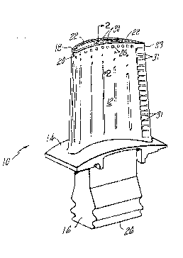
Referring to Figure 1, a turbine blade is
re~resented by the genera1 reference numeral 10.
The blade is ~abricated erom a nickel base
superalloy such as the alLoy described in ~.S.
Patent No. 4,209,348 to Duhl et al. The blade 10
has an air~oil portion 12, a platform 14, and a root
16. Recessed below the surface 18 of the blade tip
20 is a squealer pocket 22. As is also seen in
Figure 2, the blade 10 is hollow, having a cavity 24
which extends from the base 26 of the blade root 16
to near the blade tip 20. Cooling holes extend from
the cavity 24 to the external surface of the blade
- 10. During engine operation, air is flowed into the
cavity 24 and exits the blade 10 through the cooling
holes. Several of the holes 26 extend from the
cavity 24 to the airfoil surface 12; several other
holes 28 extend from the cavity 24 to the surface 18
of the blade tip 20; and several other hoies 30
extend from the cavity 24 to the squealer pocket 22.
In the blade 10 shown in the Figures, the holes 26
and 30 have a diffusion or shaped hole
configuration; while the holes 28 have a
conventional (i.e., constant geometry)
configuration. The blade 10 in Figure 1 also has
cooling holes 31 which extend from the cavity 24 to
the trailing edge 33. It should be understood that
the invention is not limited to the weld repair of a
.
. .. .
'
:
~,
: .
35~ 7
component having the same distribution of holes as
does the blade 10 shown in the Figures. As stated
above, it may be used on a broader category of
components.
As noted in the Background section, as a result
of the complex geometry of shaped cooling holes,
their formation is a technically complex, time
consuming, and expensive part of the overall blade
fabrication. Consequently, when turbine blades
having shaped holes are in need of weld repair, it
is preeerred that the holes not be welded shut, and
that their size and shape not be altered.
According to this invention, molten weld filler
metal is prevented from solidifying within cooling
L5 holes and upon any other surfaces of the blade which
are preferably kept free of the filler by a mask of
sintered ceramic particles present in the holes and
on these other surfaces. The ceramics in the mask
are nonreactive (inert) with the blade substrate,
and are thermally stable, i.e., resistant to
degradation at the welding temperatures and
resistant to thermal shock which takes place on
solidification of the molten filler metal. Further,
the ceramics are dimensionally stable, i.e., they do
not expand or contract an excessive amount during
the sintering treatment or during the welding
operation. As will be discussed below, when arc
welding techniques are used, the mask is preferably
electrically nonconductive, and prevents an arc from
being maintained between a welding electrode and the
co-ponent being weld repai-ed. Finally, the mask is
,
:
~ ,C'J~5~7
easily removed from the repaired component after
welding.
Since the composition of the superalloys used to
make modern gas turbine engine components are
S closely controlled, it is readily understood why the
ceramics in the mask must not react with the
superalloy. For similar reasons, the ceramics must
also not react with the molten filler metal.
Resistance to high temperature degradation and
thermal shock is necessary because the mask must
have sufficient structural integrity to act as a
physical barrier to keep the molten weld bead from
solidifying on the surfaces being shielded. The
mask must be dimensionally stable; in other words,
lS there should not be a drastic volumetric change in
the mask during the sintering operation or during
the welding operation. If there was such a change,
the molten weld bead might be able to solidify upon
the areas which are intended to be weld bead free.
The combined volume change during sintering and
welding should not be more than about one or two
percent.
Since arc welding techniques such as tungsten
inert gas (TIG) are preferably used in weld
repairing components according to this invention,
the sintered mask should be sufficiently
nonconductive to prevent an arc from passing between
the substrate and the welding electrode. The
ability of the mask to prevent an arc from being
maintained prevents the filler metal from being
melted, and therefor, from being deposited on the
:
., ,
.
27
_9~
surface which is masked. The need for
nonconductivity is most important when the mask is
used to shield major blade surfaces like airfoil,
tip, pLatform, etc. surfaces. The need for
electrical nonconductivity appears to be less
important when the mask is used only to s'hield
coolin~ holes.
Finally, the mask must be readily removed from
the blade a~ter the welding process. This not o~ly
includes easy removal of the mask, but also complete
removal of the mask. As can be appreciated by those
skilled in the art, the blade could be seriously
damaged during service use i~ all of the mask were
not removed after the weld operation.
The above mask properties may be achieved by
using one or more of the single or complex oxides of
Group IIA, IIIA, IVA, IIIB or IVB elements. Also,
single or complex oxides of the rare earth elements
; may be used. Preferred simple oxides include
silica, alumina, yttria, and hafnia. Preferred
complex oxides include zirconium orthosilicate and
aluminum silicate, and other similar spinel groups.
Most preferably, the cerarnic mixture contains, on a
weight percent basis, about 10-50 percent zirconium
orthosilicate (zircon), 1-20 percent alumina,
balance silica. Silica is a desired constituent
because it is, in general, nonreactive with the
blade and filler metal alloys, has good thermal
characteristics (high resistance to thermal shock
and a low thermal expansion coe~ficient) and is
readily dissolved in caustic leaching solutions.
` '' ! ''~
.
351~:7
--10--
Zircon is desired since it, too, has a high shock
resistance, and also has high thermal conductivity.
Alumina, preferably alumina fibers, are a
constituent in the ceramic mixture to add strength
to the sintered mask.
The preferred liquid carrier to use with the
silica-zircon-alumina mixture is aqueous coLloidal
silica. When colloidal silica is mixed with silica,
zircon and alumina, the silica in suspension
infiltrates the interstices between the larger
silica and zircon particles and the alumina fibers,
and enhances the leachability of the mixture after
it has been fired.
The following examples are provided to
illustrate the invention.
Example I
A mixture of ceramic constituents containing, on
a weight basis, about 64~ fused sil-ica powder, about
3% fumed silica powder, about 28~ zircon powder, and
about 3~ high aspect ratio alumina ~iber was blended
with colloidal silica to form a paste-like compound
mixture. The ratio of the ceramics to colloidal
silica was about S0-S0 by weight (i.e., between
about 30-70 and 70-30); however, the actual ratio of
constituents (i.e., ceramic to colloidal silica) is
not as important as is the resultant consistency of
the compound, which was in the range of about
20,000-50,000 centipoise. Compounds having this
range of viscosity readily adhere to metallic
surfaces, and have good ~lowability.
'
,
, ,
~?~8~
This paste-like ceramic containing compound was
used in conjunction with t:he weld repair of a
service operated turbine blade which had a
configuration similar to the blade 10 shown in
Figure 1: shaped cooling holes 26, 30 were present
in the airfoil surface 12 and in the squealer pocket
22, respectively, and conventional cooling holes 28
were present in the blade tip 20. Figure 3 shows a
turb~ne blade 10 in cross sectLon after engine
operation. As is seen by comparing Figure 3 with
Figure 2, the tip portion 20 of the engine operated
blade has been worn down, and extends less in the
outward radial direction than the tip portion 20 of
the blade before engine operation, Figure 2. The
purpose of the weld repair operation was to increase
the longitudinal dimension of the blade 10, by
adding weld filler metal to the blade tip surface
18. Prior to welding, the coating on the blade
(see, e.g., commonly assigned U.S. Patent No.
4,585,481 to Gupta) was locally removed from the tip
20, and then the squealer pocket 22 and the shaped
holes 30 within the squealer 22 were completely
filled with the compound 34. The compound 34 was
also applied onto the airfoil surface 12 adjacent to
and even with the surface 18 of the blade tip 20.
The thickness of the compound 34 on the airfoil
surface 12 was in the range of about 0.050-0.200
inches, although the maximum thickness did not
appear to be critical. The compound 34 was forced
into the shaped holes 26, 30 and the squealer pocket
Z-, ta~ing particul-- care to insuce that the holes
. ~
.
~ : ' ' ` '
35 ;L~
26, 30 were ~illed, i.e., that the compound 34 was
present along the length of each hole. (The length
of the hole was equal to the thickness of the wall
which the hole penetrated). None of the compound 34
was applied to the tip surface 18 of the blade 10,
since that was the area which was to be weld
repaired. In order to decrease the possibility that
the compound 34 on the airfoil sur~ace 12 would
contaminate or otherwise intereere with the tip
welding, the compound 34 was beveled away from the
tip 18, as shown in Figure 3.
Following a low temperature bake at about 95C
(200F), to evaporate the liquid carrier from the
compound, the blade was heated to about 540C
(l,OOOaF) for two hours to sinter the ceramic
particles to each other, and form the mask.
Temperatures as low as about 480C (900F) will
likely be useful, as will temperatures above 540C.
The maximum sintering temperature for the compound
will likely be dictated by the heat treatment limits
of the alloy from which the blade is made.
Metallographic and visual examination of the blade
after sintering showed that the mask 34 completely
filled the cooling holes and was structurally sound,
notwithstanding the presence of some small cracks
(microcracks). A deposit of weld ~iller metal 36
(Figure 4) was then applied to the blade tip surface
18 using conventional TIG welding techniques.
After;welding, inspection of the blade 10
indicated that the ceramic mask 34 on the blade
sur~ace 12 a d in the cooling holes 26, 30 was still
: ~ .
~'
~: :
,
: . .
.
,
~ ~5~7
intact. More importantly, the mask 34 kept the
holes 26, 30 from being ~illed with weld filler
metal. As is seen in Figure 4, the filler metal
weld bead 36 penetrated below the orlginal surface
18 of the blade tip 20, but was conined entirely
between the mask 34 in areas that the mask 34 was
present.
After welding, the blade 10 was lightly blasted
with alumina abrasive media, which removed nearly
all of the mask 34. Then, the blade 10 was exposed
to a caustic (e.g., sodium or potassium hydroxide)
autoclave cleaning process such as is described in
commonly assigned U.S. Patent No. 4,439,241 to Ault
et al, which completely removed any of the remaining
ceramic, and washed with a high pressure water jet
to remove the caustic and any other debris still
present.
The weld deposit 36 on the blade tip 20 was then
ma~hined to produce a blade having the desired
length, and conventionally shaped cooling holes
electrodischarge machined into the tip. (The
original holes 28 had been welded shut during the
repair operation.) Following all other required
machining, application of the required coating on
the blade surface, a post welding heat treatment,
shot peening the blade root 16, and inspection, the
; blade was in the condition shown in Figures 1 and 2,
and rea~y ~or service use.
Exam~e II
Cracks on the airfoil section of hollow vanes
used in~gas turbine engin~es are weld repaired using
the techniques of this invention. The method for
repairing such vanes is shown in Figures 5-8, where
;
,: ` :
,
~.~8S~27
-14-
the vane 40 is shown as having an internal cavity 42
and a crack 44 which extends through the airfoil
walL 46 and into the cavity 42. The ~irst step o~
this method is to remove the coating tif present) on
the airfoil internal and external vane surface. The
coating may either be removed from the entire vane,
or locally removed from areas adjacent to the crack
44. (In Figures 5-8, the blade 40 is shown ~ree o~
a coating.) Next, a ceramic compound 48 like that
in Example I is injected into the interior vane
cavity 42 so as to at least fill the area adjacent
to the crack 44. In some cases, it will be easiest
to completely fill the cavity 42, as shown in Figure
6. The compound 48 is baked and fired in ~he manner
disclosed in Example I. The cracked portion 44 o~
the vane is then ground away using, e.g., an
abrasive machining tool, (Figure 7) so that any
contamination and/or oxides present in the crack 44
are removed. This step also removes any of the
compound (designated 48' in Figure 1) which may have
flowed from the cavity 42 through the crack 44. The
vane 40 is ground until the crack 44 is completely
removed. Whether the crack 44 has been completely
removed is readily determinable by fluorescent
penetrant inspection. If the crack 44 extends
entirely through the airfoil wall 46 (as shown in
the Figures), the grinding process is performed to
expose the internal vane cavity, but so that as
little of~the ~ired ceramic mask 48 in the cavity 42
is removed. In other words, once the airfoil wall
~ 46 is penetrated, the grinding is stopped. The
::
'
:' .
:
- .. . . .
35~
ground area 52 of the vane 40 (the crack now
removed) is then repaired (filled) with weld filler
metal 54, which is applied by arc welding techniques
such as TIG. The ceramic mask 48 in the cavity 42
acts as a backer to prevent molten filler metal erom
entering and solidifying in the cavity 42. If the
eiller metal was allowed to solidify in the vane
internal cavity 42, this could complicate the
insertion of an internal cavity baffle, cause
structural problems, and/or disrupt air flow through
the cavity during engine operation. Following the
welding operation, thé mask 48 is removed by caustic
autoclave cleaning and high pressure water blast, as
discussed in the above example. The weld bead 54 is
then blended to conform with the shape of tHe
external air~oil wall surface 46, and the vane 40
recoated, heat treated, etc., as required~
Although this invention has been shown and
described with respect to a preferred embodiment
thereof, it should be understood by those skilled in
the art that other various changes and omissions in
the form and detail thereof may be made without
departing from the spirit and scope of the
invention.
.
'
'~
.