Sélection de la langue

Search

Sommaire du brevet 1288323 

Énoncé de désistement de responsabilité concernant l'information provenant de tiers

Une partie des informations de ce site Web a été fournie par des sources externes. Le gouvernement du Canada n'assume aucune responsabilité concernant la précision, l'actualité ou la fiabilité des informations fournies par les sources externes. Les utilisateurs qui désirent employer cette information devraient consulter directement la source des informations. Le contenu fourni par les sources externes n'est pas assujetti aux exigences sur les langues officielles, la protection des renseignements personnels et l'accessibilité.

Disponibilité de l'Abrégé et des Revendications

L'apparition de différences dans le texte et l'image des Revendications et de l'Abrégé dépend du moment auquel le document est publié. Les textes des Revendications et de l'Abrégé sont affichés :

  • lorsque la demande peut être examinée par le public;
  • lorsque le brevet est émis (délivrance).
(12) Brevet: (11) CA 1288323
(21) Numéro de la demande: 1288323
(54) Titre français: CONTROLEUR DE DEBIT DE GAZ DANS UN TUBE D'ESSAI
(54) Titre anglais: TEST-TUBE THROTTLE
Statut: Périmé et au-delà du délai pour l’annulation
Données bibliographiques
(51) Classification internationale des brevets (CIB):
  • G01N 01/22 (2006.01)
  • G01N 01/28 (2006.01)
  • G01N 01/40 (2006.01)
  • G01N 21/78 (2006.01)
  • G01N 31/22 (2006.01)
(72) Inventeurs :
  • KRETSCHMER, WOLFGANG (Allemagne)
(73) Titulaires :
  • WOLFGANG KRETSCHMER
(71) Demandeurs :
(74) Agent: SMART & BIGGAR LP
(74) Co-agent:
(45) Délivré: 1991-09-03
(22) Date de dépôt: 1986-11-20
Licence disponible: S.O.
Cédé au domaine public: S.O.
(25) Langue des documents déposés: Anglais

Traité de coopération en matière de brevets (PCT): Non

(30) Données de priorité de la demande:
Numéro de la demande Pays / territoire Date
P 35 42 780.9 (Allemagne) 1985-12-04

Abrégés

Abrégé anglais


ABSTRACT
The invention describes a test-tube for the quantitative
measurement of very small concentrations of gas components with a
reagent strip impregnated with chemical reagents. Arranged before
the reagent strip in the direction of flow of the test gas, is a
flow throttling element. By means of this arrangement, the test
air, which is passed through the test-tube by an air feed pump, has
its forward motion throttled to such an extent that the test air
flows slowly past the sensitive reagent strip producing a change of
colour in zones.

Revendications

Note : Les revendications sont présentées dans la langue officielle dans laquelle elles ont été soumises.


The embodiments of the invention in which an exclusive
property or privilege is claimed are defined as follows.
1. A test-tube for the quantitative measurement of
minimal concentrations of gas components with a test strip
impregnated with chemical reagents, a gas permeable,
flow-throttling holding element arranged in front of this test
strip in the flow through direction, wherein the
flow-throttling element is a fine-grained layer of a chemically
inert material which has a substantially uniform grain size.
2. A test-tube according to claim 1, characterized in
that the grains in the flow-throttling layer are spherical.
3. A test-tube according to claim 1, characterized in
that a granular reaction layer is applied to the flow
throttling element and to the reagent strip.
4. A test-tube according to claim 3, characterized in
that the reaction layer is impregnated with a reagent for
converting the polluting component to be determined into an
easily detectable chemical sequential product.
5. A test-tube according to claim 4, characterized in
that the reaction layer is impregnated with a reagent which
reacts with an unwanted accompanying substance and filters it
out,
6. A test-tube according to claim 1, characterized in
that the reagent strip is made from an impregnated absorbent
material.
7. A test-tube according to claim 1, characterized in
that the reagent strip is made from a nonabsorbent material to
which is applied a layer of an absorbent, finely granular
material which has been impregnated in a suitable manner.
-6-

8. A test-tube according to claim 1, characterized in
that one end of the reagent strip is laid around a gas
permeable mounting element in order to secure the said strip in
the test tube in the longitudinal direction thereof.
9. A test-tube for the quantitative measurement of
minimal concentrations of gas components with a test strip
impregnated with chemical reagents, a gas permeable,
flow-throttling holding element arranged in front of this test
strip in the flow through direction, wherein the
flow-throttling element is a capillary tube which is located in
the testing tube in a close fitting relationship.
-7-

Description

Note : Les descriptions sont présentées dans la langue officielle dans laquelle elles ont été soumises.

il3~3
The invention relates to a test-tube for quantitative
measurement of very small concentrations of gas components with
a reagent strip impregnated with chemical reagents.
In the case of a known test-tube of this kind, the
reagent strip, impregnated with a detecting reagent, is held to
the inner wall of the test-tube with a granular filler material
(German OS 32 36 792). It is to be regarded as a disadvantage
that, as a result of fluctuations in grain-size and packing
density, the granular filler material may cause flows of test
gas which differ widely locally. This may lead to
irregularities, and thus to inaccuracies in the display
provided by the highly sensitive reagent strip. In addition to
this, there is the danger that dust may be formed during the
filling and application of the granular filler material. If
any of this dust is deposited onto the reagent strip, it can
also cause trouble and lead to incorrect indications.
It is therefore the purpose of the invention to
provide a test-tube with which very small concentrations of gas
components may be measured and may be detected with great
accuracy with a sensitive reagent strip.
According to one aspect of the present invention,
there is provided a test-tube for the quantitative measurement
of minimal concentrations of gas components with a test strip
impregnated with chemical reagents, a gas permeable,
flow-throttling holding element arranged in front of this test
strip in the flow through direction, wherein the
flow throttling element is a fine-grained layer of a chemically
ne/~t
material which has a substantially uniform grain size.
~, . ..";, .

332~
The advantages obtained with the invention are, in
particular, that the test air delivered through the test-tube
by the feed pump has its forward motion throttled or reduced,
before ~
- 2a -

3..~ .323
, .
reaching the reagent strip, to such an extent that it flows slowly
and uniformly past the said strip, thus ensuring a clearly
determinable display.
An example of embodiment is illustrated in the drawing
attached hereto and is explained hereinafter in greater detail. In
the said drawing:
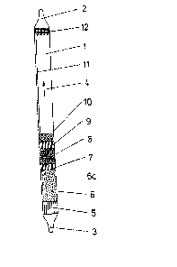
Figure 1 is a longitudinal section through a test-tube with a
reagent strip and a flow throttle according to the invention; and
Figure 2 is a longitudinal section through a test-tube with a
reagent strip and another design of flow throttle according to the
invention.
As may be seen from 1 and 2, glass test-tube 1 comprises
molten ends 2 and 3. In the direc-tion of flow 4 of the test air, the
following components are arranged in the said test-tube.
A mounting component 5 which is permeable to the test air, a
flow throttle 6 in the form of a layer finely granular, chemically
inert material (Fig. 1), or a flow throttle 6a in the form of a
capillary tube (Fig. 2), a gas permeable mounting component 7, a
granular sorption - or reaction layer 8, a gas permeable mounting
component 9, a gas permeable mounting component 10 which secures a
reagent strip 11 in the longitudinal direction of the test-tube 1
and, finally a further gas permeable mounting component 12.
The gas permeable mounting components 5, 7, 9 and 12 consist
of a synthetic material, glass, ceramic or metal.
Reagent strip 11 contains a detecting reagent for the
constituent in the air or gas under investigation to be determined,
the detection reaction producing a change in colour. In this

~.2~ 3
DS11-4361-5
connection, reaqent. str;p 11 is made oF an ahsorbent mater;a]., for
example, paper, cardboard or t.extile which is impregnated with the
detect;.ng reaqent.
However, the said reagent strip 11 may al.so consist of a
non-absorbent carri.er, for example, a synthetic material or metal,
to which ;.s appl;.ed a layer of fi.nely qranu].ar absorbent material
suitably impregnated with the detecting reagent.
~ ccord;.nq to Figure 1, flow throttle 6 arranged beEore
reagent strip ll, ;.s a finely granuJ.ar layer of chemically inert
material, preferably of uniform grain size, for example, spheres of
equal size~ This produces a definite flow resistance and thus
uniform distribution of the flow of test qas. This layer acts as a
so-called flow throttle. It serves to throttle, or slow down the
forward mot;.on t.o the test air, passed through t.he test-tube by the
feed pump, to such an extent that the said test air flows slowly
past the reagent strip. This allows the sensitive reaqent strip to
be d;..scoloured in zones and ensures a clear]y determinable display.
In Fiqure 2, flow throttle fia is in the form of a capillary
tube inserted into the qlass tube with its edges sealed, with a
spec;fic openinq and lenqth. The effect of this is similar to that
of layer 6 described above in connection with Fiqure 1 If, for the
purpose of direct determination oF the gas to be measured, no
suitable reagent is availab].e for the test-tube procedure, but a
su;.table reagent is availab~e for an eas;.ly determinable sequential
product, then it is advantageous to incorporate, after throt-tling
layer 6 according to Figure 1, or after capillary tube 6a according

to Figure 2, the granular sorption - or reaction layer 8 which is
impregnated with a reagent for converting an easily determinable
chemical sequential product.
If unwanted accompanying substances in the test gas to be
measured falsify the results, but the gas component to be determined
reacts directly with reagent strip 11, sorption - and reaction layer
8 may act as a filter to hold back these unwanted accompanying
substances selectively. In this case, layer 8 is also impregnated
with a reagent which reacts with the accompanying substance and
filters it out. In the form of a preliminary layer in ~ront of
reagent strip 11, layer 8, suitably impregnated, may serve as a
filter, and as a conversion layer, for a new chemical sequential
product, if this is necessary.
In order to take a measurement, ends 2 and 3 of the test-tube
are broken off and test air is drawn through the open test-tube in
the direction of arrow 4, by means of an air feed pump. These test
air flows firs-t through flow throttling layer 6 (Fig. 1) or capillary
tube 6a (Fig. 2), then through sorption - and reaction layer 8, after
which it flows uniformly past reagent strip 11. In the presence of a
substance to be detected, this allows sensitive reaction strip 11 to
be discoloured in zones.
, .... ... ...

Dessin représentatif
Une figure unique qui représente un dessin illustrant l'invention.
États administratifs

2024-08-01 : Dans le cadre de la transition vers les Brevets de nouvelle génération (BNG), la base de données sur les brevets canadiens (BDBC) contient désormais un Historique d'événement plus détaillé, qui reproduit le Journal des événements de notre nouvelle solution interne.

Veuillez noter que les événements débutant par « Inactive : » se réfèrent à des événements qui ne sont plus utilisés dans notre nouvelle solution interne.

Pour une meilleure compréhension de l'état de la demande ou brevet qui figure sur cette page, la rubrique Mise en garde , et les descriptions de Brevet , Historique d'événement , Taxes périodiques et Historique des paiements devraient être consultées.

Historique d'événement

Description Date
Inactive : CIB de MCD 2006-03-11
Inactive : Demande ad hoc documentée 1994-09-03
Le délai pour l'annulation est expiré 1994-03-05
Lettre envoyée 1993-09-03
Accordé par délivrance 1991-09-03

Historique d'abandonnement

Il n'y a pas d'historique d'abandonnement

Titulaires au dossier

Les titulaires actuels et antérieures au dossier sont affichés en ordre alphabétique.

Titulaires actuels au dossier
WOLFGANG KRETSCHMER
Titulaires antérieures au dossier
S.O.
Les propriétaires antérieurs qui ne figurent pas dans la liste des « Propriétaires au dossier » apparaîtront dans d'autres documents au dossier.
Documents

Pour visionner les fichiers sélectionnés, entrer le code reCAPTCHA :


Pour visualiser une image, cliquer sur un lien dans la colonne description du document (Temporairement non-disponible). Pour télécharger l'image (les images), cliquer l'une ou plusieurs cases à cocher dans la première colonne et ensuite cliquer sur le bouton "Télécharger sélection en format PDF (archive Zip)" ou le bouton "Télécharger sélection (en un fichier PDF fusionné)".

Liste des documents de brevet publiés et non publiés sur la BDBC .

Si vous avez des difficultés à accéder au contenu, veuillez communiquer avec le Centre de services à la clientèle au 1-866-997-1936, ou envoyer un courriel au Centre de service à la clientèle de l'OPIC.

({010=Tous les documents, 020=Au moment du dépôt, 030=Au moment de la mise à la disponibilité du public, 040=À la délivrance, 050=Examen, 060=Correspondance reçue, 070=Divers, 080=Correspondance envoyée, 090=Paiement})


Description du
Document 
Date
(aaaa-mm-jj) 
Nombre de pages   Taille de l'image (Ko) 
Revendications 1993-10-21 2 51
Abrégé 1993-10-21 1 13
Dessins 1993-10-21 1 20
Description 1993-10-21 5 144
Dessin représentatif 2002-03-25 1 5