Note : Les descriptions sont présentées dans la langue officielle dans laquelle elles ont été soumises.
~ z2~63
1 COMPOSITE TUB~LAR STRUCTURE
Background of the Invention
Traditionally, vehicle drive shafts have been
formed of a steel tube having a high flexural modulus
with a forged yoke welded to each end of the steel
tube. With both the tube and the yokes formed of steel
the drive shaft is a relatively heavy structure.
At certain rotational speeds, a drive shaft
can become dyn~mically unstable. The critical speed at
which the instability occurs is generally proportional
to the flexural modulus of the shaft and its moment of
inertia and generally inversely proportional to the
weight of the shaft and its length. To maintain an
acceptably high critical speed with a tubular steel
drive shaft, the drive shaft in many instances is
formed of short multiple sections and shaft support
bearings are utilized along the length of the drive
shaft which act to rotationally support the shaft sec-
tions.
Recently there has been considerable activity
in the development of composite drive shafts which are
composed of a fiber reinforced resin tube or shaft and ~;
light weight metal, such as aluminum, yokes. The com-
posite drive shaft achieves a substantial weight reduc-
tion as compared to a steel drive shaft and due to the
lighter weight, a one piece composite shaft can replace
the multi-section steel shafts, with the resultant
elimination of the shaft support bearings which are
utilized with a multi-section steel shaft.
However, a problem in the production of a
composite drive shaft has been the lack of an adequate
connection between the fiber reinforced resin tubular
member and the yokes. In one approach to providing an
adequate connection between the tube or shaft and the
35 ~ yokes, the ends of the tube/ which surround the sleeve
63
1 portion of the yoke, are connected to the sleeve
portion by rivets. In another approach, as shown in
United States Patent 4,279,275, the sleeve portion of
the yoke is provided with a plurality of longitudinally
extending grooves and the resin impregnated fibrous
material, when producing the tubular member, is wound
circumferentially over the grooves to provide an
improved mechanical connection between the tube and the
yokes.
In the ~nited Sta~es Patent 4,358,284 the
sleeve portion of the yoke is provided with circum-
ferential extending grooves or threads and the fibrous
material is wound in the grooves to provide an improved
attachment, while in Unitec States Patent 4,380,443 a
plurality of angularly extending pins are employed to
interconnect the wound tube with the sleeve portion of
the yoke.
~nited States Patent 4,248,062 proposes to
increase the bond between the wound tube and the sleeve
portion of the yoke by employing a specific winding
pattern including longitudinal helical and circumferen-
tial windings.
_ mmary of the Invention
The invention is directed to a composite
tubular structure, such as a drive shaft having an
improved attachment between the fiber reinforced resin
tubular member or shaft and the metal yokes. In
accordance with the invention, the sleeve portion of
each yoke is provided with a plurality of
longitudinally extending raised ribs or bosses which
are received in slots formed in the respective ends of
the fiber reinforced resin tubular member. Windings of
a fibrous material impregnated with the thermosetting
resin can be applied over the joint between the yokes
and the tubular member. With this construction the
~2~ i3
l torsional load is transmitted through the ribs and
slots rather than through an adhesive bonded interface
between the tubular member and the yokes.
In a modified form of the invention, the
portion of the yoke sleeve extending between the bases
of adjacent ribs is formed with a recess that extends
at acute angle to the axis of the yoke. The end por-
tions of the tubular member located between adjacent
slots define flexible tongue, ~nd thc end of each
tongue is bent inwardly and received within one of the
recesses in the sleeve portion of the yoke. An adhesive
bond is employed to secure the tips of the tongues
within the recesses as well as to bond the contiguous
portions of the tubular member to the sleeve of the
yoke.
The invention provides an improved mechanical
connection between the fiber reinforced resin tubular
member or shaft and the yokes in which the torsional
load is transmitted through the ribs and slots.
The composite drive shaft of the invention
has a substantially reduced weight over a conventional
steel drive shaft and reduces operational noise and
vibration.
The composite drive shaft of the invention
can be used for relatively long drive shafts and elim-
inates the need for shaft support bearings which are
reguired in multi-section steel drive shafts. Due to
the lesser weight, the drive shaft produces less stress
on the supporting bearings.
By use of the fiber reinforced resin tubular
member along with forged aluminum yokes, the drive
shaft is corrosion resistant.
Other objects and advantages will appear in
the course of the followinq description.
., ~ ,,
63
1 Description of the Drawings
The drawings illustrate the best mode
presently contemplated of carrying out the invention.
In the drawings:
Fig. 1 is a side elevation of the composite
drive shaft of the invention with parts broken away in
section;
Fig. 2 is an exploded perspective view showing
an end of the fiber reinforced resin tubu~ar member and
the yoke;
Fig. 3 is an exploded perspective view of a
modified form of the invention showing the ends of the
tubular member and the yoke;
Fig. 4 is a longitudinal section of the con-
nected members as illustrated in Fig. 3; and
Fig. 5 is a trznsverse section taken a~ona
line 5-5 of Fig. 4.
Description of the Illustrated Embodiment
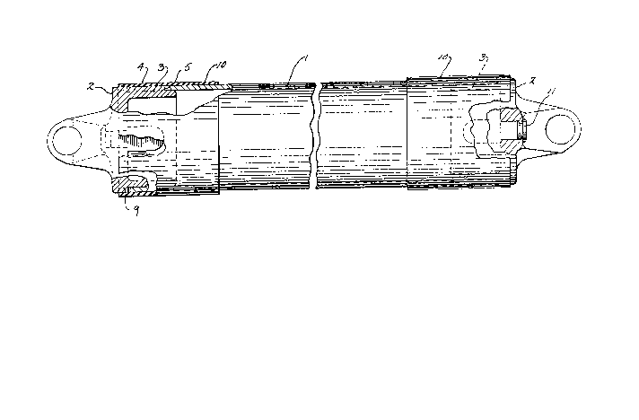
Fig. l illustrates a composite drive shaft
composed of a fiber reinforced resin shaft or tubular
member l and a pair of metal yokes 2, formed of alum-
inum or the like, each of which is connectecl to an end
of the tubular member l.
Tubular member l ;s formed of a fibrous
material such as glass fibers, or a combination of
glass and graphite fibers, which are wound in a pattern
to provide the desired mechanical properties in the
tubular member. A combination of different winding
patterns can be used, such as substantially circum-
ferential windings, helical windings and substantially
longitudinal windings. The particular winding pattern
and fibrous material employed in forming tubular rnember
l is conventional and in itself forms no part of the
invention.
. .
~2~963
1 The fibrous material in tubular member 1 is
bonded together by a cured thermosetting resin, such as
an epoxy or polyester resin.
As best illustrated in Fig. 2, each yoke 2 is
provided with a generally cylindrical sleeve portion 3
and a plurality of longitudinal raised ribs or bosses 4
are formed on the outer surface of the sleeve 3. As
shown, four ribs 4 are utilized, but depending upon the
p~rticular application, o,~e or more such ribs can be
employed. Each rib is provided wi.h a generally curved
or rounded outer end 5 as shown in Fig. 2.
As shown in Fig. 2, the ends of the tubular
member 1 are provided with longitudinal slots 6 which
receive the ribs 4 on yoke 2. Each slot 6 is bordered
by a pair of generally parallel walls 7 and a generally
curvea or rounded base 8 which engages the rounded end
5 of the respective rib 4. When tubular member 1 is
applied over the sleeve 3, the ends 5 of ribs 4 bottom
out aa,ainst the bases 8 of slots 6 so that the end of
the tubular member 1 is spaced out of contact with the
shoulder 9 on the outer surface of yoke 2.
As an alternate construction, the ribs 4 can
be formed on the inner surfce of the sleeve 3, and the
sleeve inserted over the tubular member 1, so that the
ribs are received in slots 6.
The contiguous surfaces of tubular member 1
and yokes 2 are bonded together, preferably by a
thermosetting resin or an adhesive system.
To provide additional attachment between
tubular member 1 and each yoke 2, a fibrous material
impregnated with a thermosetting resin can be wound
around the outer surface of tubular member 1 and yoke 2
and across the joint therebetween, as indicated by
10. The outer surfaces of ribs 4 are substantially
flush with the outer sur'ace of .he tubular member 1 so
12~1~3963
1 that the resulting windings 10 will have a smooth outer
surface or contour. Alternately, a metal clamping band
can be clamped over the joint in place of the fibrous
windings lO.
Each yoke 2 is provided with an axial bore
which is normally enclosed by a plug 11. During the
application of the windings 10, the composite struc-
ture, including tubular member 1 and yokes 2, can be
sup2orted by 2 central shaft that extends through the
axial openings in yokes 2. The shaft serves to proper-
ly align the two yokes 2 and tubular member 1 during
winding of the layer 10. After the windings have been
applied, the shaft is removed from the composite struc-
ture and the axial bores are closed by the plugs 11.
Figs. 3-5 illustrate a modified form of the
invention in which the composite drive shaft includes a
fiber reinforced resin shaft or tubular member 12 and a
pair of metal yokes 13. The cylindrical sleeve portion
14 of each yoke 13 is formed with a plurality of long-
itudinaily extending raised ribs or bosses 15. As
illustrated in Fig. 5, sleeve portion 14 includes six
ribs 15 but it is contemplated that any number of ribs
can be utilized.
Each rib 15 is bordered by a pair of angul-
arly extending sides 16 which are connected together by
a generally square end 17. As best illustrated in Fig.
4, the portions of sleeve 14 extending between the
bases of adjacent ribs 15 are formed with recesses 18
which extend at an acute angle of about 10 to 20 with
respect to the axis of sleeve 14.
As best shown in Fig. 3 each end of tubular
member 12 is provided with a plurality of tongues 19
which border slots 20. Tongues 19 taper or converge
inwardly, as illustrated in Fig. 3, and are receivec n
the spaces between ribs 15 on sleeve 14. The tongues
~L ~A '~
~8~963
1 19 are relatively flexible and the tips 21 of the
tongues are bent or deformed inwardly and are received
within the angular recesses 18 in sleeve 14. In this
construction, the bases of slots 20 bottom out against
the ends 17 of ribs 15 and the contiguous surfaces of
the tubular member 12 and sleeve 14 are bonded together
by an adhesive such as a thermosetting resin. Bonding
of the bent ends 21 of tongues 19 within recesses 18
serves to enhance th~ conr.ectior between the tubular
member 12 and yokes 13
As.in the case of the first embodiment, wind-
ings 22 of a fibrous material impregnated with a
thermosetting resin can be applied over the outer sur-
face of the tubular member 12 and yokes 13 to bridge
the joint between th~ members.
The invention provides an improved mechanical
interlock between the fiber reinforced resin tubular
member or shaft and the metal yokes in which the
torsional loaa is transmitted between the ribs and
slots rather than through an adhesive bonded interface
between the members.
The composite drive shaft has a substantially
reduced weiaht over a conventional steel drive shaft
and provides reduced operational noise in service.
While the above description has illustrated
the invention as applied to a cornposite drive shaft, it
is contemplated that t'he composite tubular member can
be used in other load transmittinq applications.