Sélection de la langue

Search

Sommaire du brevet 1290078 

Énoncé de désistement de responsabilité concernant l'information provenant de tiers

Une partie des informations de ce site Web a été fournie par des sources externes. Le gouvernement du Canada n'assume aucune responsabilité concernant la précision, l'actualité ou la fiabilité des informations fournies par les sources externes. Les utilisateurs qui désirent employer cette information devraient consulter directement la source des informations. Le contenu fourni par les sources externes n'est pas assujetti aux exigences sur les langues officielles, la protection des renseignements personnels et l'accessibilité.

Disponibilité de l'Abrégé et des Revendications

L'apparition de différences dans le texte et l'image des Revendications et de l'Abrégé dépend du moment auquel le document est publié. Les textes des Revendications et de l'Abrégé sont affichés :

  • lorsque la demande peut être examinée par le public;
  • lorsque le brevet est émis (délivrance).
(12) Brevet: (11) CA 1290078
(21) Numéro de la demande: 1290078
(54) Titre français: AGENCEMENT CALOPORTEUR POUR COMPOSANTS GENERATEURS DE CHALEUR MONTES SUR UN SUBSTRAT
(54) Titre anglais: COOLING STRUCTURE FOR HEAT GENERATING ELECTRONIC COMPONENTS MOUNTED ON A SUBSTRATE
Statut: Périmé et au-delà du délai pour l’annulation
Données bibliographiques
(51) Classification internationale des brevets (CIB):
  • H01L 23/34 (2006.01)
  • H01L 23/433 (2006.01)
  • H01L 23/473 (2006.01)
(72) Inventeurs :
  • MINE, SHINJI (Japon)
  • SHIMONISHI, TERUMI (Japon)
(73) Titulaires :
  • NEC CORPORATION
(71) Demandeurs :
  • NEC CORPORATION (Japon)
(74) Agent: SMART & BIGGAR LP
(74) Co-agent:
(45) Délivré: 1991-10-01
(22) Date de dépôt: 1988-07-22
Licence disponible: S.O.
Cédé au domaine public: S.O.
(25) Langue des documents déposés: Anglais

Traité de coopération en matière de brevets (PCT): Non

(30) Données de priorité de la demande:
Numéro de la demande Pays / territoire Date
157800/1987 (Japon) 1987-10-15
185182/1987 (Japon) 1987-07-24
189201/1987 (Japon) 1987-07-29
204168/1987 (Japon) 1987-08-19

Abrégés

Abrégé anglais


ABSTRACT
A cooling structure for cooling heat generating elec-
tronic components mounted on a substrate is disclosed. It includes
a cold plate fixed on the substrate which is provided with first
through holes opposed to the upper surfaces of the heat generating
electronic components. Flow paths are formed inside the cold
plate for circulating a coolant. An inlet is provided on a side
of the cold plate for supplying the coolant to the flow paths.
An outlet is provided on a side of the cold plate for exhausting
the coolant from the flow paths. Pistons are inserted and
held inside the through holes so that the lower surfaces of the
pistons come into contact with the upper surfaces of the heat
generating electronic components.

Revendications

Note : Les revendications sont présentées dans la langue officielle dans laquelle elles ont été soumises.


- 7 -
What is claimed is:
1. A cooling structure for heat generating electronic
components mounted on a substrate comprising:
a cold plate fixed on said substrate which is provided
with first through holes opposed to the respective upper
surfaces of said heat generating electronic components;
flow paths formed within said cold plate for
circulating a coolant;
an inlet provided on a side of said cold plate for
supplying said coolant into said flow paths;
an outlet provided on a side of said cold plate for
exhausing said coolant from said flow paths; and
pistons inserted through and held within said first
through holes so that the lower surfaces of said pistons
come into contact with said upper surfaces of said heat
generating electronic components.
2. A cooling structure as claimed in Claim 1, wherein
an intermediary member made of a heat-conductive material
is interposed between each of said lower surfaces of said
pistons and a corresponding one of said upper surfaces of
said electronic components.

- 8 -
3. A cooling structure as claimed in Claim 1, wherein
each of said pistons comprises:
a longitudinal slit extending through the center
thereof;
a threaded hole formed within said slit; and
a screw which is inserted into said threaded hole
so as to expand said slit for causing the wall surface
of the first through hole, in which the piston is inserted,
to snugly come into contact with the outer surface of
the piston.
4. A cooling structure as claimed in Claim 2, wherein
said intermediary member has a first -threaded hole; and
each of said pistons comprises: a longitudinal slit
extending through the center thereof;
a second through hole provided at the center thereof;
a first screw inserted through said second through
hole to be engaged with said first threaded hole;
a second threaded hole formed within said slit at a
position near said second through hole; and
a second screw inserted into said second threaded
hole so as to expand said slit for causing the wall surface
of the first through hole, in which the piston is inserted,
to come into contact with the outer surface of the piston.

- 9 -
5. A cooling structure as claimed in Claim 1, wherein
said first through holes are threaded holes and said
pistons is screws to be engaged with said first through
holes.
6. A cooling structure as claimed in Claim 5, wherein
an intermediary member made of a heat-conductive material
is interposed between each of the lower surfaces of said
pistons and a corresponding one of the upper surfaces of
said electronic components.
7. A cooling structure as claimed in Claim 1, wherein
said pistons are cylindrical.
8. A cooling structure as claimed in Claim 2, wherein
said heat-conductive material is one of metal and silicone
rubber.
9. A cooling structure as claimed in Claim 6, wherein
said heat-conductive material is one of metal and silicone
rubber.

Description

Note : Les descriptions sont présentées dans la langue officielle dans laquelle elles ont été soumises.

7~
Cooling Structure for Heat Generating Electronic
Components ~ounted on a Substrate
Background of the Invention
The invention relates to a cooling structure for
heat generating electronic components such as integrated
circuit (IC) chips.
U.S. Patent No. 4,628,990 discloses an example of
prior art cooling structures for IC chips. The prior
art structure disclosed, however, has a disadvantage
that since a long transmission path of the heat from
each of the IC chips to the coolant increases the thermal
resistance of the path, the heat generated from the
IC chips cannot effectively be dispersed. In addition,
since the prior art structure is designed to be used
in planar packaging, its height is tall and it is not
applicable to three-dimensional packaging.
Summary of the Invention
An object of the invention is, therefore, to
provide a cooling structure free of the above-mentioned
disadvantages of the prior art structure.
According to an aspect of the invention, there is
provided a cooling structure for heat generating electronic
components mounted on a substrate which comprises: a cold

1~9(~V~7~
plate fixed on said substrate which is provided with firs'
through holes ooposed to the upper surfaces of the heat
generating electronic components; flow paths formed inside
the cold plate for circulating a coolant; an inlet provided
on a side of the cold plate for supplying the coolant to
the flow paths; an outlet provided on a side or the cold
plate for exhausting the coolant from the flow paths; and
pistons inserted and held inside the through holes so that
the lower surfaces of the pistons come into contact with
the upper surfaces of said heat generating electronic
components.
Brief Description of the Drawings:
Other features and advantages of the invention will
become more apparent from the following detailed description
when taken in conjunction with the accompanying drawings
in which:
Fig. 1 shows a perspective view with a partially
exploded section of first through third embodiments of
the invention;
Fig. 2 shows a cross-sectional view of the first
embodiment;
Fig. 3A and 3B are plane and side views of a piston
used in the first embodiment, respectively;
Fig. 4 is a cross-sectional view of the second
embodiment;

~'9~ 78
-- 3 --
Figs. 5A and 5B are plan2 and side views of a piston
used in the second embodiment, respectively; and
Fig. 6 shows a cross-sectional view of the third
embodiment.
In the drawinys, the same reference numerals xepresent
the same structural elements.
De~ailed Description of the Preferred Embodiments
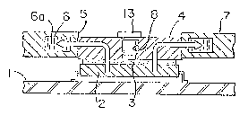
Referring to Figs. 1 and 2, a first embodiment of
the invention comprises a substrate 1, IC chips 2 mounted
on the substrate 1, elastic heat-conductive sheets 3 of
silicone rubber placed on the upper surfaces of the
chips 2, pistons 4 in contact with the upper surfaces
of the sheets 3, and a cold plate 7 having a plurality
of holes 5 and flow paths 6 which cools the pistons 4
inse~ted in the holes 5 with a coolant 6a circulating
through the flow paths 6~ The heat generated from the
chips 2 is transmitted through the sheets 3, the pistons
4 and the plate 7 to the coolant 6a. Compared to the
heat transmission path of the prior art strubture
mentioned above, the heat transmission path according
to the invention is considerably short to achieve an
effective radiation of heat.
Referring to Figs. 3A and 3B, each of the pistons 4
is provided with a threaded hole 8 and a slit 9, and has
the same structure as that disclosed in the above-mentioned

-- 4 --
U.S. Patent. Each piston is held within a corresponding
one of the holes 5 of the cold plate 7 with a screw 1~ in
a manner similar to that disclosed in the abo~Je-mentioned
U.S. Patent. (Its description is omitted for simplicity's
sake.)
The plate 7 is provided with an inlet 10 and an
output 11 for the coolant 6a on a side thereof. The plate
7 is separated from the substrate 1 by a predetermined
distance by stiffeners 12. The plate 7, the stiffeners 12
and the substrate 1 are fixed with screws 19. The plate 7
may be made integrally with the stiffener 12.
A second embodiment shown in Figs. 1 and 4 comprises
a substrate 1, IC chips 2 mounted on the substrate 1,
heat-conductive plates 14 of metal attached on the upper
surfaces of the chips 2 with an adhesive agent 15, pistons
20 in contact with the plates 14, and a cold plate 7 having
flow paths 6 and a plurality of holes 5 for insertion of
the pistons 20. The plate 7 cools the pistons 20 inserted
in the holes 5 with a coolant 6a circulating through the
flow pa-ths 60 The heat generated from each chip 2 is
transmitted through a path extending from the agent 15 via
the plate 14, the piston 20 and the plate 7 to the coolant
6a. Referring to-Figs. 5A and 5B, each of the pistons 20
has a through hole 19, a threaded screw hole 17 and a
slit 9.
The pistons 20 are inserted into the holes 5 of the

o~
-- 5
cold plate 7 to come to contact with the upper surfaces of
the plates 14, respectively. Eirsc threaded screws 13 are
driven into the through holes 19 of the pistons 20 to be
engaged with threaded screw holes 16 formed in the heat
conductive plates 14 until flanges ~ormed at the tops o' ~he
screws 13 comes to abut against the upper surfaces of
the pistons 20, respectively. This fixes the pictons 20
on the plates 14. Then, second threaded screws 18 are
mated with the screw holes 17 of the pistons 20. By
tightening the screws 18 in the screw holes 17, the slits
on the pistons 20 are expanded to fix the pistons 20
snugly in the holes 5 of the cold plate 7 through friction.
Referring to Fig. 6, a third embodiment of the
invention comprises a substrate 1, IC chips 2 mounted on
the substrate 1, and a cold plate 7 having flow paths and
a plurality of threaded holes 23 for insertion of pistons
21. The plate 7 cools the pistons 21 inserted in the
threaded holes 23 with a coolant 6a circulating through
the flow paths. A threaded portion 21a is formed on the
outer periphery of each of the pistons 21 to be mated with
a corresponding one of the threaded holes 23 of the cold
plate 7. Eac-h of the lower surfaces of the pistons 21
and a corresponding one of the upper surfaces of the
chips 2 are either directly or through an intermediary
member 24 in contact with each other. The intermediary
member 24 may be a heat conductive compound having a

~90(~78
- 6 -
elasticity or an elastic heat-conductive sheet.
While this invention has been described in conjunction
with the preferred embodiments thereof, it will no~J readily
be possible for those skilled in the art to put this
invention into practice in various other manners.

Dessin représentatif
Une figure unique qui représente un dessin illustrant l'invention.
États administratifs

2024-08-01 : Dans le cadre de la transition vers les Brevets de nouvelle génération (BNG), la base de données sur les brevets canadiens (BDBC) contient désormais un Historique d'événement plus détaillé, qui reproduit le Journal des événements de notre nouvelle solution interne.

Veuillez noter que les événements débutant par « Inactive : » se réfèrent à des événements qui ne sont plus utilisés dans notre nouvelle solution interne.

Pour une meilleure compréhension de l'état de la demande ou brevet qui figure sur cette page, la rubrique Mise en garde , et les descriptions de Brevet , Historique d'événement , Taxes périodiques et Historique des paiements devraient être consultées.

Historique d'événement

Description Date
Inactive : CIB de MCD 2006-03-11
Le délai pour l'annulation est expiré 2000-10-02
Lettre envoyée 1999-10-01
Accordé par délivrance 1991-10-01

Historique d'abandonnement

Il n'y a pas d'historique d'abandonnement

Historique des taxes

Type de taxes Anniversaire Échéance Date payée
TM (catégorie 1, 6e anniv.) - générale 1997-10-01 1997-09-16
TM (catégorie 1, 7e anniv.) - générale 1998-10-01 1998-09-17
Titulaires au dossier

Les titulaires actuels et antérieures au dossier sont affichés en ordre alphabétique.

Titulaires actuels au dossier
NEC CORPORATION
Titulaires antérieures au dossier
SHINJI MINE
TERUMI SHIMONISHI
Les propriétaires antérieurs qui ne figurent pas dans la liste des « Propriétaires au dossier » apparaîtront dans d'autres documents au dossier.
Documents

Pour visionner les fichiers sélectionnés, entrer le code reCAPTCHA :


Pour visualiser une image, cliquer sur un lien dans la colonne description du document. Pour télécharger l'image (les images), cliquer l'une ou plusieurs cases à cocher dans la première colonne et ensuite cliquer sur le bouton "Télécharger sélection en format PDF (archive Zip)" ou le bouton "Télécharger sélection (en un fichier PDF fusionné)".

Liste des documents de brevet publiés et non publiés sur la BDBC .

Si vous avez des difficultés à accéder au contenu, veuillez communiquer avec le Centre de services à la clientèle au 1-866-997-1936, ou envoyer un courriel au Centre de service à la clientèle de l'OPIC.


Description du
Document 
Date
(aaaa-mm-jj) 
Nombre de pages   Taille de l'image (Ko) 
Revendications 1993-10-21 3 69
Dessins 1993-10-21 3 59
Abrégé 1993-10-21 1 18
Description 1993-10-21 6 154
Dessin représentatif 2000-07-10 1 7
Avis concernant la taxe de maintien 1999-10-31 1 178
Taxes 1994-09-14 1 72
Taxes 1996-09-17 1 85
Taxes 1995-09-21 1 74
Taxes 1993-09-19 1 47