Sélection de la langue

Search

Sommaire du brevet 1291388 

Énoncé de désistement de responsabilité concernant l'information provenant de tiers

Une partie des informations de ce site Web a été fournie par des sources externes. Le gouvernement du Canada n'assume aucune responsabilité concernant la précision, l'actualité ou la fiabilité des informations fournies par les sources externes. Les utilisateurs qui désirent employer cette information devraient consulter directement la source des informations. Le contenu fourni par les sources externes n'est pas assujetti aux exigences sur les langues officielles, la protection des renseignements personnels et l'accessibilité.

Disponibilité de l'Abrégé et des Revendications

L'apparition de différences dans le texte et l'image des Revendications et de l'Abrégé dépend du moment auquel le document est publié. Les textes des Revendications et de l'Abrégé sont affichés :

  • lorsque la demande peut être examinée par le public;
  • lorsque le brevet est émis (délivrance).
(12) Brevet: (11) CA 1291388
(21) Numéro de la demande: 1291388
(54) Titre français: BAC DE RANGEMENT DE BOITIERS DE DISQUES AUDIO SIMPLES ET DOUBLES
(54) Titre anglais: DUAL AND SINGLE AUDIO DISC BOX STORAGE TRAY
Statut: Périmé et au-delà du délai pour l’annulation
Données bibliographiques
(51) Classification internationale des brevets (CIB):
  • B65D 85/57 (2006.01)
  • G11B 33/04 (2006.01)
(72) Inventeurs :
  • MASTRONARDO, PATRICK (Etats-Unis d'Amérique)
  • LIU, FU J. (Taïwan, Province de Chine)
(73) Titulaires :
  • PATRICK MASTRONARDO
  • FU J. LIU
(71) Demandeurs :
(74) Agent: DOUGLAS S. Q.C. JOHNSONJOHNSON, DOUGLAS S. Q.C.
(74) Co-agent:
(45) Délivré: 1991-10-29
(22) Date de dépôt: 1987-07-17
Licence disponible: S.O.
Cédé au domaine public: S.O.
(25) Langue des documents déposés: Anglais

Traité de coopération en matière de brevets (PCT): Non

(30) Données de priorité de la demande:
Numéro de la demande Pays / territoire Date
887,839 (Etats-Unis d'Amérique) 1986-07-21

Abrégés

Abrégé anglais


DUAL AND SINGLE AUDIO DISC BOX
STORAGE TRAY
ABSTRACT OF THE DISCLOSURE
A storage tray has opposed first sets of spaced ribs forming parallel
compartments and a second set of shorter ribs disposed between the first sets of
ribs with the spacing being one first rib and one adjacent second rib being sized
to slidably receive one single compact audio disc box, so that two single compact
audio disc boxes fit every compartment. Two adjacent single boxes may be
removed, and then one dual audio disc box is received in the compartment
between adjacent first ribs, and with the second rib being slidably received in the
back recess of a conventional dual audio disc box. The storage tray is self-
interlocking with another storage tray so as to form a self-constructing cabinet.

Revendications

Note : Les revendications sont présentées dans la langue officielle dans laquelle elles ont été soumises.


THE EMBODIMENTS OF THE INVENTION IN WHICH AN EXCLUSIVE
PROPERTY OR PRIVILEGE IS CLAIMED ARE DEFINED AS FOLLOWS:
1. A storage tray for audio disc boxes comprising:
opposed top and bottom walls and a back wall
interconnecting said top and bottom walls, a plurality of
elongated first ribs disposed on at least one of the top
and bottom walls, with the spacing between adjacent first
ribs being about equal to the thickness of a conventional
dual audio disc box, and a plurality of second ribs, and
one of said second ribs being disposed between adjacent
first ribs with the distance between a first rib and an
adjacent second rib being about equal to the thickness of a
conventional single audio disc box, and wherein the length
of the second rib being sized to slidably fit a back recess
formed in the conventional dual audio disc box, said second
ribs are disposed on said back wall and are shorter than
said first ribs and are centrally disposed between said top
wall and bottom wall, whereby one dual disc box is stored
in the compartment between adjacent first ribs with the
second rib fitting into the back recess or two single audio
disc boxes are stored in the compartment with each single
disc box disposed between a first rib and a second rib.
2. The storage tray of claim 1, wherein the second
ribs are disposed 90° from the first ribs.
3. The storage tray of claim 2, said tray being U-
shaped.
- 7 -

4. The storage tray of claim 2, further comprising
first ribs facingly disposed on the top wall and bottom
wall.
5. The storage tray of claim 1, further comprising
end walls between said top wall and bottom wall, and in
parallel disposition to said first ribs.
6. The storage tray of claim 5, said end walls formed
with a portion contiguous to said back wall.
-
7. The storage tray of claim 6, said tray comprising
a unitary molded plastic piece.
8. The storage tray of claim 1, said second ribs
comprising rounded edges.
9. The storage tray of claim 1, further comprising
third ribs being disposed between said first ribs, said
third ribs being of lesser height than said first ribs, and
being coplanar with said second ribs.
10. A storage tray construction for audio disc boxes
comprising:
opposed top and bottom walls, and a back wall
interconnecting said top and bottom walls, said top and
bottom walls comprising means for self-interconnecting
- 8 -

other storage trays to the outside surface of the top and
bottom walls, a plurality of elongated first ribs disposed
on at least one of the inside surfaces of the top and
bottom walls, with the spacing between adjacent first ribs
being about equal to the thickness of a conventional dual
audio disc box and a plurality of second ribs, and one of
said second ribs being disposed between adjacent first ribs
with the distance between a first rib and an adjacent
second rib being about equal to the thickness of a
conventional single audio disc box, and wherein the length
of the second rib being sized to slidably fit a back recess
formed in the convential dual audio disc box, whereby one
dual audio disc box is stored in the compartment between
adjacent first ribs with the second rib fitting into the
back recess, or two single audio disc boxes are stored in
the compartment with each single disc box disposed between
a first rib and a second rib, and whereby a plurality of
said trays are self-interconnected to form a storage tray
construction.
11. The storage tray of claim 10, further comprising
end walls on said top wall and bottom wall, and in parallel
disposition to said first ribs, said end walls being formed
with cooperative means for interlocking said trays in a
side-by-side construction.
- 9 -

Description

Note : Les descriptions sont présentées dans la langue officielle dans laquelle elles ont été soumises.

~9~3~
FIELD OF ~
This invention relates to a storage tray for compact audio discs.
BACKGROUND AND DISCUSSION OF THE PRIO~ ART
With the invention of compact audio discs, the protection and
storage of these discs presented a problem for manufacturers QS well as
consumers. At first a single compact audio disc was packaged in a
rectilinear clear plastic box. One prior art construction to store these
single discs was a tray with upper and lower opposed spaced parallel
elongated ribs, with the spacing between the ribs being sized to slidably
receive one single disc box.
~ ong-playing works QS well a multiple related works had to be
recorded on two discs which gave rise to the dual disc plastic box~ This
plastic box folded open in a book-like manner in two opposed sections, with
one disc being housed in each section.
The art then desired a storage tray which would readily accept
both the single disc boxes as well as the dual disc boxes, so that a consumer
in purchasing a disc storage tray would be assured that the tray would
accomodate both single and dual boxes in a reasor~able storage mode.
SU.UMARY OF THE INVENTION
A storage tray is formed with elongated parallel first ribs
which first ribs are spaced at distances approximately equal to the
thickness of a dual compact audio disc box so as to form a compartment
for the dual box, and one each of a second set of ribs is disposed between Q
pair of adjacent first ribs, with the space between one first rib ~nd one
second rib being approximately equal to the thickness of a single audio disc
box, and with the second rib sized to slidably fit into the back recess of the
--2--
.

1~9~3~38
spine of the conventional dual audio disc box, so that each compartment
receives either one dual audio disc box or two single audio disc boxes. The
second ribs are disposed on the back wall of the tray and at an angle of 90
from the first ribs.
Third ribs are disposed between the first ribs to guide the single
boxes into place, and the third ribs are sized so that a dual box fits
between upper and lower third ribs and rests on the lower third rib.
The tray is self-interlocking with other trays so as to form a
cabinet.
BRIEF DESCRIPTION OF THE DRAWINGS
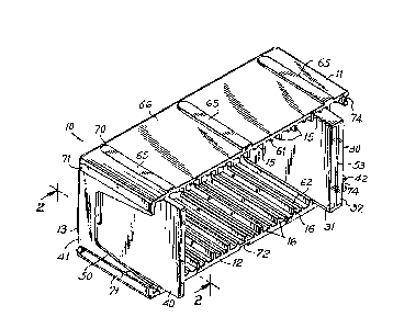
FIG.l is a perspective view of the storage tray of the present invention;
FIG. 2 is an enlarged side elevational view of the storage tray taken along
line 2-2 of FIG.l;
FIG. 3is a fragmentary sectional view taken along line 3-3 of PIG.l;
FIG. 4 is a sectional view taken along line ~4 oî FIG. 3;
FIG. 5 is a sectional view taken along line 5-5 of FIG. 3; and
FIG. 6 is a sec~ional view taken along line 6-6 of FIG. 3
DISC USSIO N OF THE PR EFER RED E BO DIM ENTS
Referring to the FIGS., there is shown the storage tray of the
present invention generally referred to by reference numeral 10. Tray 10
is of unitary injection molded construction and has a top wall 11, a bottom
wall 12, and a rear or back wall 13, so as to form a U-shaped structure 50,
with bottom wall 12 resting on a flat horizontal surface (not shown). End
walls 41 and 42 partially enclose the tray 10 in structure 50. Back wall 13
may also be mounted through mounting hole 19 to a flat vertical surface
--3--

3~3
(not shown).
A plurality of elongated spaced parallel ribs I S and 16 are-
formed in the top and bottom walls I 1 and 12, respectively. Ribs 15 and 16
are formed in opposing top and bottom wall surfaces 17 and 18,
respectively, so as to provide a series of compartments 20 disposed
between adjacent ribs 15, or 16, or 15 and 16. The distance A between
_
adjacent ribs 15, and similarly between adjacent ribs 16, is approximately
equal to thickness B of dual compact audio disc box 30. Box 30 is of
conventional construction and contains two standard compact ~udio discs,
with each disc being stored on separate sides 31 and 32, with back spine
midline 33 ~nd front midline 53, so that sides 31 and 32 part in a book-like
manner on opposite sides of midline 53 for access to the individual discs.
The conventional dual box 30 is provided with a vertical slot 35
formed in the spine 36. Slot 35 is ~isposed in the middle of spine 36 and is
of the entire length C
Back wall 13 of tray 10 is formed with a series of spaced
parallel ribs 38 which are shorter than sides 15 and 16, and have a length n,
which is shorter than the length C of slot 35. Ribs 38 are centrally
disposed on the inside surface 34 of wall 13. It is important to note that
while ribs 38,are disposed at 90 from ribs 15 and 16, ribs 13 bisect
distance A so as to form dual or twin cornpartments 39, with a distance E
between rib 38 and rib 15 or rib 16, which distance E is about equal to the
thickness F of a conventional single audio disc box 40. Ribs 38 are formed
wi;h rounded inner ed~es 44 for ready insertion in slot 35.
Third sets of ribs 61 and 62 are formed in and extend from toP
and bottom walls 17 and 18. respectively. Ribs 61 and 62 are parallel to

~X'3~ 88
ribs 15 and 16, respectively, and are of substantially lesser height than ribs
15 and 16. Ribs 61 and 62 are coplanar with ribs 38, but disposed at 90
ther0to. :
By the aforesaid manner of construction, single disc box 40 is
slidably received in compartment 39 between one rib 38, ribs 61 and 62,
and ribs 15 and 16. Two single disc boxes 40 fit within one compartment
20. With the removal of the two single disc boxes 40, one dual disc box 30
may then be slidably received in compartment 20 between adjacent ribs 15
at the top and between adjacent ribs 16 at the bottom. Box 30 is disposed
between ribs 61 und 62, ~nd mounts lower rib 62. With full ins~rtion of box
30, rib 38 is slidably received in slot 35 to securely mount box 30, with box
spine 36 abutting back w~ll 13.
Another important aspect of the present invention is the serf-
interlocking COnStrllCtiOn. A series of three elongated flanges 65 are
formed on the top slJrface 66 of top wall 11. Flanges 65 are formed with
chamfered edge 67 extending from front edge 68 to rear portion 69, at
which point flange 65 is formed with rearward curved portion 70. A series
of two parallel elongated flanges 71, similary constructed to flanges 65,
are formed on end wall ~1. A series of three elongated groves 72 are
formed on the bottom surface 73 of bottom wall I2. Grooves 72 are spaced
and sized to slidably receive flanges 65 of a second tray ~not shown) so as
to provide two trays in a self-interlocking vertic~l stacked mode. End wall ~ '
42 is formed with two parallel elongated grooves 74, which are similar to
grooves 72 and are speced and sized to slidably receive flanges 71 of a
second tray (not shown) so as to provide two trays in a self-interlocking
sid~by-side mode. ln the aforesaid manner, a plurality of trays 10 may be
-5-

$313~
self-interlocked to form a free standing cabinet or structure.
There has been shown a storage tray which can readily store
both single audio disc boxes as well as dual audio disc boxes in a secure and
convenient manner.
Various modifications are with the contemplation of the
invention including the mounting of the storage tray 10 in a carrying case
construction for portable use.
It is also within the contemplation of the invention to mount
the U-shaped tray in an upright manner so that in effect the back wall
rests on a flat horizontal surface.
.
.

Dessin représentatif
Une figure unique qui représente un dessin illustrant l'invention.
États administratifs

2024-08-01 : Dans le cadre de la transition vers les Brevets de nouvelle génération (BNG), la base de données sur les brevets canadiens (BDBC) contient désormais un Historique d'événement plus détaillé, qui reproduit le Journal des événements de notre nouvelle solution interne.

Veuillez noter que les événements débutant par « Inactive : » se réfèrent à des événements qui ne sont plus utilisés dans notre nouvelle solution interne.

Pour une meilleure compréhension de l'état de la demande ou brevet qui figure sur cette page, la rubrique Mise en garde , et les descriptions de Brevet , Historique d'événement , Taxes périodiques et Historique des paiements devraient être consultées.

Historique d'événement

Description Date
Inactive : CIB de MCD 2006-03-11
Inactive : Demande ad hoc documentée 1994-10-29
Le délai pour l'annulation est expiré 1994-04-30
Lettre envoyée 1993-10-29
Accordé par délivrance 1991-10-29

Historique d'abandonnement

Il n'y a pas d'historique d'abandonnement

Titulaires au dossier

Les titulaires actuels et antérieures au dossier sont affichés en ordre alphabétique.

Titulaires actuels au dossier
PATRICK MASTRONARDO
FU J. LIU
Titulaires antérieures au dossier
S.O.
Les propriétaires antérieurs qui ne figurent pas dans la liste des « Propriétaires au dossier » apparaîtront dans d'autres documents au dossier.
Documents

Pour visionner les fichiers sélectionnés, entrer le code reCAPTCHA :


Pour visualiser une image, cliquer sur un lien dans la colonne description du document. Pour télécharger l'image (les images), cliquer l'une ou plusieurs cases à cocher dans la première colonne et ensuite cliquer sur le bouton "Télécharger sélection en format PDF (archive Zip)" ou le bouton "Télécharger sélection (en un fichier PDF fusionné)".

Liste des documents de brevet publiés et non publiés sur la BDBC .

Si vous avez des difficultés à accéder au contenu, veuillez communiquer avec le Centre de services à la clientèle au 1-866-997-1936, ou envoyer un courriel au Centre de service à la clientèle de l'OPIC.


Description du
Document 
Date
(aaaa-mm-jj) 
Nombre de pages   Taille de l'image (Ko) 
Abrégé 1993-10-22 1 28
Dessins 1993-10-22 3 133
Revendications 1993-10-22 3 86
Description 1993-10-22 5 156
Dessin représentatif 2001-11-18 1 23