Note : Les descriptions sont présentées dans la langue officielle dans laquelle elles ont été soumises.
3~7
~KI ~OOT ANl) SAF~TY ~IN!~IN~
Back~round of the Tnvention
This invention re]ates to ski boots and ski bindings9 and in particular
to an operative combination of a ski boot and integral binding which is
simple, effective and which allows release in all directions. This invention
also relates to improvements in the structure of a ski boot, including
the facilitation of walking in the boot, rearward release to prevent knee
injuries and adjustability of the degree of forward and rear lean of the
skier's leg when the boot is worn.
As the technology relating to skis and ski boots advances, leg
injur es encountered bv skiers have been reduced dramatically. ~lowever,
the vast majority of all commercial skiing combinations comprise a ski
boot, a binding for attachment of the boot to a ski, and, of course, a
ski. Typically, the manufacturers of the skiJ binding and boot are
different, leading to the possibility of incompatability, but, more
importantlv, preventing more radical advances in skiing safety by
permittin~ integration of these three operative e]ements or of flt least
the ski boot and binc3ings. Therefore, bindings. while experiencing minor
~ ~ advances over the years, have st;ll c]ung to the decades old structure of
., ~
a toe portion and a heel portion, which clamp respectively to the skier's
boot toe and boot heel. 13ecause the typical boot sole is quite ]ong
c]amping at these great ]engths necessitates a rather long lelrer arm for
release.
U.S. Patent No. 3,918,732 describes a considerable improvement
in sl;i binc~in~s, where the degree of reliability of the release oî tl~e
: ::
1~99L637
binding is increased ~reatly over conventional heel and toe bindings.
~lowever, the structure requires the skier to be somewhat elevated above
the ski in relation to elevations with conventional heel and toe bindings,
an additional height which may be objectionable to some skiers. Also.
with one exception, the binding of this patent is a separate structure
from the boot, necessitating an additional plate and therefo e additional
weight. l'hus, while a considerable improvement over conventional heel
and toe bindings, the invention of this patent is not the perfect answer
to problems encountered with heel and toe bindings.
t~onventional ski boots have a relatively stiff, long sole in order
to function compatibly with conventional heel and toe bindings. As a
result, walking in ski boots for any distance whatsoever is an
uncomfortable and awkward procedure. Also, conventional ski boots of
the clam shell type (having forward and rear cuffs) have onlv limited
]ean, with resistance to change of lean being the same in forwerd and
rearward directions. Tn this type of ski boot, and indeed, in most modern~
stiff ski boots, ankle injuries have largely been eliminated, but,
unfort~mately the stiffness of the boot and inability to bend rearwardly
has created new knee problems, flnd in particular tears of the anterior
cruciate ligaments. This type of injury can often end a skier's skiing
career, or force the truly avid skier to wear a knee brace in order to
~be able to ski in the future.
ummarv of he Tnvention
The invention pertains to a combined ski boot and binding for
releassbly attaching the ski boot to a ski. Include-? in the combination
is first connecting means secured to the ski beneath the boot and a
second connecting means secured to the boot, with the second connecting
:
::
~ ::
637
means spanning the first connecting means ~lith portions in a fore-and-
aft re]ationship generall~ along the length of the ski. The fore portion
is located beneath the boot and at least part of the aft portion is located
beneath the boot, depending on the form of the invention. ~eans is
provided for re]easedly coupling the first and second connecting means
so that they may be separated in the forward, backward or lateral
directions, or a combination thereof, under predetermined load conditions.
The coupling system includes a major plunger means and a minor plunger
means aligned with one another and generally parallel to the longitudinal
axis of the ski, one of the plunger means being located in the first
connecting means and the other of the plunger means being located in
the second connecting means. First and second spaced and aligned sockets,
each being engaged by one of the plunger means, also comprises part of
the coupling system, one of the sockets being located in the first
connecting means and the other of the sockets being located in the second
connecting means. Each of the plunger means is adjustably urged by a
spring into engagement with its respective engaged socket. Finally, the
invention includes meflns for temporarily withdrawing one of the plunger
means from its engaged socket to permit separation of the first and
second connecting means without load thereon.
In accordance with the preferred embodiment of the invention, the
major plunger is located in the aft portion of the second connecting
means and the minor plunger is located in the first connecting means.
The plungers are oriented in the same direc~ion, facing forward in the
normal direction of trsvel of the ski. The major plunger may be located
at an elevation above the ski which is slightly greater than the elevation
of the minor plunger means.
637
Each plunger has a nose formed at a particular angle, with the
corresponding socket being similarly shaped. The holding force of the
binding which determines release in the lateral direction is thus determined
by a combination of that angle, the force of the spring, and the spacin~
of the sockets, since for lateral release, one plunger acts as a fulcrum
for the other pl~mger, which releases.
For forward and rear release, fore and aft fulcrum members are
mounted on the ski beneath the boot. The fl~crum members may be
adjusted to change the lever arm for forward and rear release, and
therefore the amount of force required to release the skier from the ski
in these directions.
The fore portion of the second connecting means is preferably
immediately adjacent to, and in front of, the first connecting means.
Thus, any forward thrust of the ski in relation to the skier will not tend
to compress the minor plunger means and therefore adversely increase
temporarily the lateral release settings for the binding. The fore portion
includes a pair of opposed lateral plunger guides to guide the plunger
during lateral release of a ski from the combined sW boot and binding
of the invention.
In order to withdraw one of the plungers from its socket to permit
easy release of the boot from the ski, the one plunger includes an inte~ra]
collar. A rotatable cam is provided, secured to a shaft and mounted
adjacent to and bearing on the collar. A cam actuation arm is secured
to the shaft to permit rotation of the shaft, which causes engagement
of the cam on the collar, ancl withdrawing or extending of the one plunger
means, dependin~ on the direction of rotation of the actuation arm.
Preferably, the one plunger means is located in the aft portion of the
:
'
37
5-
second connecting means on the boot, and the actuation arm comprises
a release lever extending from one end of the shaft adjacent to the ski
boot. The release lever includes an enlarged actuation element for easy
gripping by the skier, or for engagement by a ski pole tip to facilitate
release. In another form of the invention, the one plunger means is
located in the first connecting means on the ski, and the actuation arm
comprises a release lever extending from one end of the shaft adjacent to
a side of the ski boot.
The major plunger means is mounted to control separation in the
forward and rearward directions, while the minor plunger means is mounte~
to control separation in the lateral direction. Preferably, the sockets
are spaced from one another a distance of up to about three inchest
thereby creating a ]ever arm for release in the lateral direction of up
to three inches.
In the preferred embodiment of the invention, both plunger means
and, indeed the entire second connecting means are located beneath the
boot. In another form of the invention, the major plunger is located on
the boot in the aft portion of the second connecting means, but the
means which adjustably urges the plunger means into engagement with
its respective second means comprises a spring which is mounted vertically
behind the heel of the boot. A ~inkage is provided connecting the spring
to the major plunger means. ln yet another form, the major plunger is
located on the boot, and the spring is mounted horizontally on the ski
behind the heel of the boot.
The ski boot includes a foot shell and an integral sole. The shell
comprises unattached first and second shell segments which are secured
to the sole, one of the segments overlapp;ng the other at approximately
~ .
37
the location of the ball of a foot when within the boot. The separation
of the two shell segments at this location provides a living hinge in the
sole in the vicinity of the overlap of the segments. In accordance with
the preferred embodiment of the invention, the first segment is mounted
to slide within the second segment while pivoting about the living hinge.
The invention includes means to lock the first segment relative to the
second segment to prevent such sliding when the skier is not walking and
when the boot is secured to a ski. The lock means comprises a displaceable
stop mounted in the second segment and engaging the first segment. The
first segment includes a raised flange captured within the second segment,
with the stop engaging one side of the flange when locking of the first
and second segments is required.
The ski boot according to the invention includes forward and rear
cuffs, and a strap attached to the forward cuff for seeuring the rear
cuff to the forward cuff when the boot is worn. The invention includes
means releasably securing one end of the strap to the forward cuff so
that under predetermined rearwardly-directed load conditions, the strap
will separate from the forward cuff to permit free movement of the
rear cuff. The means for releasably securing preferably comprises a
notch in the strap and a strap channel in the forward cuff, and includes
an adjustable spring-loaded plunger extending into the channel and
engaging the notch.
In the preferred form of the invention, the actua-tion arm for
releasing the two connecting means of the binding extends behind the
rear cuff. If the strap securing the two cuffs together is released~ the
rear cuf~ wi~l tend to automatically disengage the boot from the ski by
striking and pushing the arm downwardly as the cuff opens.
,
;~
~L2~
The forward cuff is hinged for forward and
rearward pi~oting of the leg of a skier when the boot is
worn. The invention includes means for separately
controlling the degree of resistance to forward and
rearward lean of the skier, comprising a pair of
oppositely directed springs connected between the forward
cuff and an immobile portion of the boot. Thus,
resistance to forward lean can be increased or decreased
relative to the r~sistance to rearward lean, providing0 diffPrent settings, as desired.
The invention also includes means for
setting a minimum forward lean of the front cuff. This
means comprises an attitude strap secured to the forward
cuff, and also attached to the foot shell of the boot. A5 series of holes or detents are included in the attitude
strap, and a displaceable stop is mounted in an immobilP
portion of the boot in registration with and engageable
with each of the holes or detents in order to adjust the
forward lean of the front cuff.
According to an aspect of the invention,
in combination, a ski boot and a binding for releasably
attaching the ski boot to a ski, comprises
a. first connecting means secured to the ski
beneath the boot,
b. second connecting means secured to the
boot, said second connecting means
spanning said first connecting means with
portions in a ~ore-and-aft relationship
generally along the length of the ski, the
~ore portion being located beneath the
boot and at least part o~ said a~t portion
being located beneath the boot,
c. means for releasably coupling said first
and second connecting means so that said
first and second connecting means may be
separated in the forward, backward, or
lateral directions, or a combination
7~
thereo~, under predetermined load
conditi.ons, said coupling means including
i. a major plunger means and a minor plunyer
means aligned with one another in the same
direction and generally parallel to the
longitudinal axis of the s~i, one of said
plunger means being located in said first
connecting means and the other of said
plunger means being located in said second
connecting means,
ii. first and second spa~ed and aligned socket
means, each being engaged by one of said
plunger means, one of said socket means
being located in said first connecting
means and the other of said socke~ means
being located in said second connecting
means.
iii. each of said plunger means including means
adjustably urging said plunger means into
engagement with its respective engaged
socket means, and
d. means for temporarily withdrawing one of
said plunger means from its engaged socket
means to permit separation of said first
and second connecting means without load
thereon.
In accordance with another aspect of the
: invention, in combina-tion, a ski boot and a binding for
releasably attaching the ski boot to a ski, comprises
a. first connecting means secured to the ski,
b. second connecting means secured to the boot,
c. means for releasably coupling said first and
second connecting means so that said first and
second connecting means may be separated under
predetermined load conditions, and
d. a foot shell and an integral, resilient and
unitary sole for said boot, said shell
: ~,
~ ~Z~3~7
7b
comprising unattached first and second shell
segments both secured to said sole in a fore-
and~aft relationship, one of said shell
segments overlapping the other of said shell
segments at approximately the location of the
ball of a foot when within the boot forming a
discontinuity in said shell at the overlapping
of said segments, thereby forming a living
hinge in said resilient sole in the vicinity of
the overlapping o~ said segments.
In accordance with another aspect of the
invention in combination, a ski boot and a binding ~or
releasably attaching the ski boot to a ski, comprises
a. first connecting means secured to the ski,
b. second connecting means secured to the boot,
c. means for releasably coupling said first and
second connecting means so that first and
second connecting means may be separated under
predetermined load conditions,
d. said boot including forward and rear cuffs and
a flexible strap attached to said forward cu~f
and extending about said rear cuff for securing
said rear cuff to said forward cuff, and
e. means for releasably securing said strap to
said forward cuff so that under predetermined
; rearwardly-directed load conditions said strap
will separate ~rom said forward cuff to permit
free movement of said rear cu~f.
, ~ Brief Des,,cription of_ he Drawings
The invention is described in greater detail in
the following description of examples embodying the best
mode of the invention, taken in conjunction with the
; drawing figures, in which:
Figure l is a side elevational view of a
combined ski boot and ~inding according to the invention;
;3'7
7c
Figure 2 is a side elevational view similar to
Figure 1, with portions omitted and with the springs for
forward and rear lean control being illustrated;
Figure 3 is an enlarged partial top plan view
of the invention, as illustrated in Figure 1, with the
ski omitted;
Figure 4 is a top plan view of the ski binding
portion of the invention, with the ski boot omitted,
; ~ '
::~
~Z~37
Figure 5 is a side elevational view thereof, shown in relation to
the ski and ski boot, and including. in phantom, release positions for the
incorporated ski brake and release arm;
Figure 6 is a plan view of the release cam according to the
inventi on;
Figure 7 is a cross sectional view taken along lines 7-7 of Figures 6;
Figure 8 is a top plan view of yet another form of the ski-mounted
portion of the binding of the invention;
Figure 9 is a side elevational view thereof;
Figure 1û is a bottom plan view thereof;
Figure 11 is a top plan view of the heel portion for the ski boot
which engages the ski-mounted portion of the first form of the invention
shown in Figllres 8 through 10;
Figure 12 is a side elevational view thereof;
Figure 13 is a bottom plan view thereof;
Figures 14A, 14B and 14C are, respectively, top, end and side
views of the toe socket portion, or fore portion, of the ski binding of
the invention;
Figure 15 is a side elevational view of the front or minor plunger
of the invention;
~ igures 16A and 16B and 16C illustrate, respectively, top, side
elevationa~ and rear views of a guide for the p]unger for ~igure 11;
Figure 17 is an elevational view of a socket for the rear, or rnajor,
plunger of the invention;
FigLIres 18A and lBB illustrate, respectively, side and top views
of engagement of the rear p]unger in its socket;
~Z9~63~
g
Figure 19 is an e1evational view, partly in cross section, showing
the orientation of the socket for the rear plun~er in re]ation to the ski;
Figure 20 is a top plan view of an nlternative embodiment of the
invention, with the ski boot omitted;
Figure 21 is an enlarged, side elevational view of the alternative
embodiment of Figure 20, with a portion of the ski boot illustrated as well.
Figure 22 is a top plan view of the ski-mounted portion of the
binding of another alternative form of the invention;
~ igure 23 is a side elevational view thereof, show;ng the release
position in phantom; and
Figure 24 is a side elevational view of yet another form of the
invention.
Descriptions of Ex m~les Embodying the Best Mode of the Invention
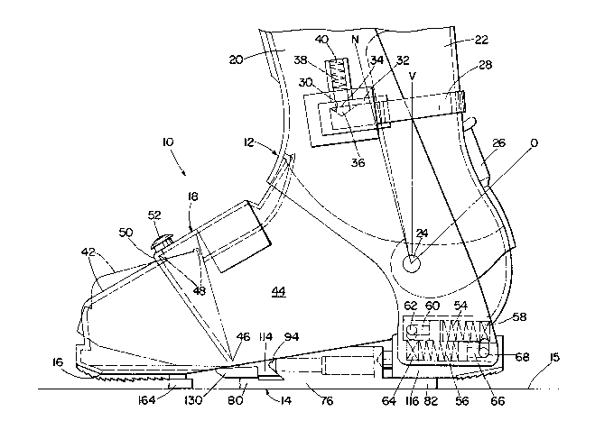
A combined ski boot and binding according to the invention is
shown ~enerally at 10 in the drawing figures. It is comprised of a ski
boot portion 12 and a binding portion 14 which is partially incorporated
into the ski boot 12 and partially secured to a ski 15, as ~qill become
evident from the following description of the sW boot 12 and binding 14.
The ski boot 12 is of the clam shell type, having an integral sole
16 from which a foot shell 18 extends, and including a forward cuff 20
~; and ~ rear cuff 22 which pivot about a central pivot 24 1Ocated on
opposite sides of the ski boot (only one side of the ski boot bein~
illustrated in the drawing figures). The forward cuff 20 overlies the rear
~uff 22, with the portion of the rear cuff 22 beneath the forward cuff
20 being shown in phantom in the drawing figures. The ski boot 12 may
also include a conventional adjustment means 26 for adjusting the ~it of
the boot to the individual wearer's foot.
: : :
3~
--10-
A strap 28 is used for securing the rear cuff 22 to the forward
cuff 20. As is conventional, the strap 28 is secured to one side of the
forward cuff 20 and extends about the rear cuff 22, being releasably
engaged to the opposite side of the forward cuff 20. The type of
attachment of the strap 28 to the one side of the forward cuff 20 has
not been illustratedy and may be a buckle or other conventional means
which will be quite evident to those skilled in the art. The opposite end
of the strap 28 engages means for releasably securing the strap to the
forward cuff 20 so that under predetermined rearwardly-directed load
conditions, the strap 28 will separate from the forward cuff 20 to permit
the rear cuff 22 to freely pivot rearwardly. To this end, the strap 28
includes a notch 30, and a strap channel 32 is secured to or formed in
the inside of the forward cuff 20. An adjustable spring-loaded plunger
34 extends into the strap channel 32 and has a plunger nose 36 shaped
to engage the notch 30.
Under normal load conditions, the rear cuff 22 bears against the
strap 28, which in turn bears against the plunger 34 by means of the
notch 30. The plunger 34 is normally held in place by means of a spring
38, the foree of which may be adjusted by an adjustment screw 40. If
the rearward force exerted by the cuff 22 against the strap 28 exceeds
the holding force of the spring 38, the plunger 34 rises against the spring
38, allowing the strap 28 to become disengaged from the plunger 34 and
therefore permitting the rear cuff 22 to open. The holding force of the
spring 38, a.s adjusted by the adjustment screw 403 may be varied as
desired to aid in preventing an anterior cruciate ligament tear in a skier's
knee.
3L2~
The foot shell 18 is separated into first and second shell segments
42 and 44. As best shown in Figures 1 and 2, the second shell segment
44 overlaps the first shell segment 42, creating a living hinge 46 in the
sole 16 at approximately the location of the ball of a foot when within
the boot. The hinge 46 aids a skier tremendously while walking in a ski
boot 12, since the typical ski boot has a rigid sole, thus having a fulcrum
point at the toe when walking9 rather than at the ball of the foot. The
ski boot 12 of the present invention does not suffer that deficiency.
For proper functioning of the binding 1~, the sole 16 ~nust normally
be rigid, and therefore the fulcruming of the hinge ~6 must be eliminated.
To this end, the first shell segment 42 includes an upstanding flange 48,
and the second shell segment includes a downwardly depending,
corresponding flange 50. The flanges interengage as shown so that the
shell segment 42 may not be inadvertently withdrawn out of sliding
engagement within the shell segment 44. In order to lock the first shell
segment 42 relative to the second shell segmenet 44, a displaceable stop
52 is provided, engaging the flange 48. The stop 52 includes a spring
(not iUustrated) biasing the stop 52 in the postion illustrated 50 that
when the shell segments 42 and 44 are in the bold orientation shown in
Figures 1 and 2 with the nange 48 sandwiched between the flange Sû
and stop 52, the sole 16 is rigid, while if the stop is lifted to permit
,,
the flange 48 to pass therebeneath, the sole 16 is aUowed to freely pivot
about the living hinge 46, as shown in phantom in Figures 1 and 2.
:
NormaUy, in a clam shell-type ski boot arrangement, the front
cuff 20 is rigidly fixed in place, and any forward movement of the cuff
is due to either the flexibility of the material of the cuff, or the
incorporation of a flexible insert into the cuff. 7'o control both forYvard
3~
-12-
and rearward excursion of the cuff 20, incorporated into the ski boot 12
is a pair of sprin~s 54 and .~6 which are secured to the front cuff 20.
The spring 54, which is adjustable by means of a screw adjustment 58,
bears upon a plunger 60 which in turn bears upon a pin 62 secured to
either the sole 15 or the foot shell 18. Similarly, the spring 56, which
is adjusted by means of a screw adjustment 64, is secured to the forward
cuff 20, and besrs on a plunger 66 which in turn bears on a pin 68
secured to either the sole 16 or the foot shell 18. The spring 54
compresses upon forward ]ean ag~inst the forward cuff 20, and therefore
controls the degree of forward lean, while the sprin~ 58 compresses upon
rearward lean of the cuf~ 20, and therefore controls the degree of
rearward movement of the cuff 20 when the ski boot 12 is worn. J~ue
to the separate screw adjustments 58 and 64, it should be evident that
the forward and rearward lean can be adjusted independantly of one
another.
In a typical ski boot of the clam shell type, the forward cuff is
normally locked at a particular angle, so that the skier, when wearing
the boot, must stand at that predetermined angle. The ski boot 12
includes means for variably setting the forward lean of the cuff 20. ~s
shown in Figure 1, the ski boot 12 includes an attitude strap 70 secured
to the forward cuff 20, and extending within the foot shell 18. The
strap 70 includes a series of holes or detents 72 (Figure 3), and a
displaceable stop 74 is mounted in the sheU segment 44 in registration
with and engageable with each of the holes 72. The stop 74 is spring
biased into the orientation illustrated, and must be lifted to be disen~aged
from an enga~ed hole 72.
,~
:
:
37
The vertical is indicated in Figures 1 and 2 by V. The normal
attitude of the forward cuff 20 is indicated by N, flnd may be altered
depending on adjustment of the attitude strap 70. The open orientation
of the rear cuff 22 is indicated by 0, approximately 45 degrees from the
vertical V, thus allowing plenty of space for insertion of a skier's foot,
and also opening quite adequately to help prevent anterior cruciate
ligament tears.
The binding 14 includes two primary portions, a first connecting
means secured to the ski 15 beneath the boot 12, and a second connecting
means secured to the boot. Those portions are illustrated in detail in
the first embodiment of Figures 1 through 19.
The first connecting means is designated generally ~t 76 in drawing
figures, and is best shown in Pigures 8 through 10. It comprises a central
block 78 and extending forward and re~r support portions 80 and 82 which
are preferably integral extensions of the block 78. The block 78 and
support portions 80 and 82 are provided with a series of mounting apertures
84 to permit the connecting means 76 to be securely attached to a ski.
It is preferred that at least sorr e of the apertures 84, such as those
shown in the support portion 82, be elongated somewhat to accommodate
~lexing of the ski beneath the connecting means 76.
The block 78 includes a stepped longitudinal central bore in which
i`
a spring 86 and plunger 88 are located. The spring 86 bears against an
enlarged head or flange 90 on the plunger 88. An adjustment scre~v 92
is provided for altering the force with which the spring 86 bears upon
the enlarged flange 90. The plunger 88 has an extending nose 9~ which,
as will be seen below, engages a corresponding socket. The nose 94
extends through a bore 96 in ~ guide 98 which is preferaMy of metal
~2~37
--14-
and hardened to prevent any ~ouging or binding. The guide 98 is secured
to the Mock 78 by means of a pair of screws 100 (Figure 16). A socket
plate 102 having a socket 104 and sdjustment aperture 106 (for providing
access to the adjustment screw 92) is mounted in the block 78 immediately
adjacent to the adjustment screw ~2. The socket plate 102 is best shown
in Figures 17 through 19, ancl mar be secured to the block 78 with screws
passing through attachment apertures 108.
For halting a runaway ski, the first connecting means 76 also
incorporates a conventional ski brake llO having a spring 112 which biases
the brake 110 against the block 78 to a substantiall~ vertical orientation
when the ski boot 12 is not attached to ski, thst orientation being shown
in phantom in Figures 1 and 5.
The second connecting means of the binding 14 comprises two
parts secured to the ski boot 12. Those parts are a fore portion 114 and
an aft portion 116. As best shown in the elevational drawing figures,
the aft portion 116 takes the place of a heel of the ski boot 12, while
the fore portion 114 is located beneath the arch.
The fore portion 114 preferably comprises a single met~llic
structure having a socket 118 shaped to be en~aged by the nose 94 of
the plunger 88. Also, for upward release of the binding 14 at the toe,
the fore portion 114 includes a ~-shaped gap 120 in a lower extension
.~
122. For guiding the plun~er ~8 during release or reattachment of the
elements oî the binding 14, the fore portion 114 also includes a pair of
guide grooves 124. For attachment of the fore portion 114 to the so]e
16 of a ski boot 123 the fore portion 114 includes a series of holes 126.
The fore portion 114 is provided with a channel 128 which may
carry an antifriction device 130 (Figures 1 and 2) secured thereto in a
637
hole 132. The antifriction ~levice 130 may be made of any friction-
reduclng plastic or other composition, as appropriate.
The aft portion 116 is best shown in Figures 11 through 13. It
includes a stepped longitudinal central bore in which are mounted a
plunger 134 having a flange 136 engaged by a spring 138 bearing against
an adjustment screw 140. AdJustmenî of the screw 140 determines the
compression force of the spring 138 against the flange 136. The aft
portion 116 is also provided with a series of attachment aperatures 142
and a removable cover plate 144 which is secured to the aft portion 116
by appropriate fasteners in holes 146.
The plunger 134 includes a nose 148 angled to engage the socket
104. The plunger 134 is mounted to be temporarily withdrawn from the
socket 104 to permit separation of the binding 14, and therefore removal
of the sW boot ] 2 from attachment to the first connecting means 76
when secured to a ski 15. To this end, a rotatable lateral shaft 152 is
secured within the aft portion 116 and includes a pair of integral cams
154 which are adjacent to, and bear upon, the flange 136. The cams
154 are spaced on opposite sides of the plunger 134. The sh~ft 152
includes a pair of integral collars 154 to allow proper ali~nment of the
shaft 152? and includes threads 158 at either end. A cam actuation arm
or lever 160 is appropriately secured to the threads 158 and extends
about the heel of the ski boot 12 when the plunger 134 is in its normal
orientation extending from the aft portion 116. The actuation arm 160
includes an enlarged actuation element 162 which may be engaged by
the skier's hand or the tip of a skier's ski pole in order to rotate the
actuation arm 160 to the released orientation sho~,~rn in phantom in Figures
1 and 5. In that orientation, as best shown in Figure S, the plunger 134
~3~637
-16--
is with(lrawn the against the force of the spring 138 by the cams 154,
and therefore the nose 148 of the plunger 134 is out of engagement with
the socket 104.
The noses of the plungers 88 and 134 are angled to aid in adjusting
ho]ding force of the binding 14. The angles may range from 50 to 90
degrees, with the mated sockets having corresponding conical angles.
Also, the lower extension 122 and mating portion of the block 76 are
similarily angled to determine a range of holding force. Those angles
may vary from 30 to 45 degrees from horizontal.
The binding 14 functions as follows. With the first connecting
means 76 attached to a ski 50, and the fore and aft portions 114 and
116 secured to the ski boot 12, the actuation arm 160 is rotated to the
downwnrd position shown in phantom in Figures 1 and 5. Doing so causes
the cams 154 to withdraw the plunger 134 into the aft portion 116,
allowing the skier to step on the ski 15 over the fi~st connnection means
76. If desired, a toe guide (not illustrated) can be mounted on the ski 15
to a;d in guiding the skier onto the ski 15. When the skier is in the
proper orientation, the plunger 88 engages the socket 11~, and in order
to secure the skier in place on the ski 15, the actuation arm 160 is
rotated to the normal orientation shown in the drawing figures, flllowing
the p]unger 134 to engage the socket 104~ The slder is then he]d firmly
in place.
The plunge 134 is the major plunger, in that it controls forward
and rear release of the binding 14, while the plunger 88 is the minor
plunger, in that it provides for R latera] release of the binding 114, the
rear plunger 134 serving as a fulcrum point for such lateral release. As
explained above, the bearing force of each of the plungers 88 and 134
--17--
is adjustable by means of the respective ac1justment screws 92 and 140,
permitting different release settings to accommod~te skiers of different
weights and skiing abilities. Because of the different functions served
by the plungers 88 and 134, the plungers need not be at equal elevations
flbove the ski 150. Thus, to accommodate the major plunger 134 in the
heel of the ski boot 12, the ~naior plunger 134 is located at a greater
elevation above the ski 15, and is angled downwardly slightly~ as well.
That downward angle may be on the order of six degrees.
For release in the forward direction, a fulcrum member 164 is
mounted on the ski 150. The location of the fu1crum member 164
determines the lever arm between the fulcrum member 164 and the
plunger 134, and therefore, given a particular setting of the spring 138,
will dictate the amount of force necessary to separate the ski boot 12
from the ski 15 in the forward direction. Judicious placement of the
fulcrum member 164 changes the length of the lever arm, and therefore
the forward release characteristics. Similarly, the rear support portion
82 of the block 78 dictates the lever arm for the plunger 134 in the
rear release direction. The support portion 82 serves as a fulcrum member
for rearward release, and will dictate rearward release characteristics
depending upon its extent beneath the boot 12. As explaine~ above, the
fore portion 114 includes a lower extension 1~ which, as best shown in
Figure 5, extends within a corresponding groove 166 formed in the block
78 and the guide 98. On rearward release, the extension 122 captured
beneath the groove 166 forces the s1ci boot 12 to move forwardly relative
to the block 78, compressing the rear plunger 134 against the force of
the spring 138. Full release occurs when the nose 94 of the plunger 88
passes through the gap 120.
63~
-18-
It is preferred thnt the sockets 104 and 118 be seperated from
one another a distance of up to about 3 inches, therefore providing a
very short lever arm for release in the lateral direction. Unlike
convention~l bindings, which are attached to the toe and heel of the
boot, and therefore have a ]ever arm of typically 12 inches or more,
misadjustment of the holding force with the three inch lever arm of the
present invention will not tend to have such disasterous effects on the
leg of a skier as does misadjustment with a lever arm of 12 inches or more.
Figures 20 and 21 illustrate an alternative form of the invention.
The first connecting means 76 and fore portion 114 remain the same,
and therefore the same reference numerals are used throughout~ Also,
for the purposes of description, certain items have been omitted for
clarity of description. For example, the ski brake 110 has been omitted,
although, obviously, it would be used in combination with the block 78.
Also, in Figure 20, certain portions of the first connecting means 76,
such ~s the support portions 80 and 82, have been omitted, but are shown
in Figure 21. The major change between the embodiment of Figures 20
and 21 is in the aft portion of the binding and in a separate retention
means, both of whieh are described immediately below.
The block 78 in the embodiment of Figures 20 ~nd 21 includes a
retention member 168 which is secured thereto. A seperate, second
retention member 170 is secured to the underside of the sole 16 of the
ski boot 12. As best seen in Figure 20, when the ski boot is secured to
the ski, the retention members 168 and 170 abut. Thus, during skiing,
where there sudden decelaration of the ski relative to the skier (and
therefore forward momentum of the ski boot relative to the first
connecting means 76), the abutting retention members 168 and 170 prevent
-19-
compression of the two retention plungers, yet do not affect release of
the ski boot from the ski in the forward direction, since if the boot rises
slightly, as occurs as a forward fall begins, the retention members 168
and 170 no longer abut since the member 170 has risen above the member
168, and therefore the binding is free to release in the norma] fashion.
The reten~ion members 168 and 170 prevent compression of the plungers
due to a forwardly impacting longitudinal force, thus preventing
compression of the retention springs and undesired increasing of the
release force necessary for the binding to separate.
In the embodiment of ~i~ures 20 and 21, the aft portion of the
ski binding, generally designated at 172, includes a plunger 174 which
engages the socket 104 of the socket plate 102 in a fashion identical to
that described above. The socket 174 is terminated by a flange 176
having a spherical surface which engages a ball 178. The ball 178, in
turn, engages the similarly-shaped end of a horizontal link 180 which
~oins, and bears against, a vertical link 182. The vertical link 182 is
topped by a flange 184 upon whi~h bears a spring 186 capped by an
adjustment screw 188. The adjustment screw 188 is used to vary the
bearing force of the spring 186. The flange 184 also bears on n seat
190 which limits the downward excursion of the vertical link 182. Also
beflring on the ball 178 is a circlùar plate 192 extending from a cylindrical
housinF 194. The diameter of the housing 19~ is on the order of at least
as great as the diameter of the ball 178. The plate 192 is urged against
the ball 178 by a spring 196 within the housing 194 which also bears
agaînst an adjustment s~rew 198.
A horizontal arm 200 bears on the opposite side of the ball 178.
The arm 20û extends from the aft portion 172 and is joined to a lever
637
-20-
arm 202, which may be integral with the arm 200, and which is topped
by an actuation element 204, identical to the actuation element 162.
The arm 200 also includes a pin 206 which bears against a fixed camming
surface 208.
The compression force of the spring 186 bears through the links
180 and 182 through the ball 178 to the p~unger 174. In order to release
the compression force of the spring 186 bearing against the plunger 174,
the ]ever arm 202 is rotated to the downward, opened position shown in
Figure 21. During rotation, the pin 206 bears flgainst the camming
surface 208, causing the arm 200 to force the ball 178 against the plate
192, compressin~ the spring 196. The camming surface 208 is also curved,
in a fashion not illustrated, to accommodate the rotation of the arm 200
during this procedure. When the ball 178 compresses the plate sufficiently,
the p]unger 174 is freed and ma~ be withdrawn into the aft portion 172
permitting separation of the ski boot from the ski. Rejoining the ski
boot to the ski is via the opposite procedure.
As illustrated in phantom in ~igure 21, the spring 186 need not
be vertical in order to function properly. Furthermore, it should be
evident that the lever arm 202 may, if desired, be conIigured to extend
behind the ski boot rather th~n to one side, as shown in Fi~ure 21.
ures 22 and 23 illustrate an alternative form 76' of the first
connecting means. Where elements are identical to elements of the first
:
form of the invention, those e]ements either bear identical reference
numbers, or have been omitted. Also, given the form of the connecting
: `:
means 76' OI Figures 22 and 23, and the fact that the means for permitting
~; separation of the first and second connecting meflns is ]ocated in the
connecting means 76', obvious]y the shaft 152 and cams 154 would be
:
,
-:
'~ ;
63~
--21--
eliminated, along with the actuation arm 160, and the aft portion 116
~ould therefore simp]y include an internal spring 138 bearing upon a
flan~e 136 of the plunger 134.
The connecting means 76t includes a hori~ontal shaft 210 frorn
which opposite lever arms 212 extend. The arms 212 may each be topped
by an actuation element 214. A pair of springs 216 are engaged about
the shaft 210 to maintain the arms 212 in the normal, upright orientation
as shown in bold fashion in Figure 23.
A pair of CQms 21û are secured to the shaft 21û and, in the normal
orientation, bear against a socket plate 220 carrying a socket 222 which
is identical to the socket 104. The socket plate 220 includes a hinge
pin 224 about which the plate 220 may rotate. Stops 226 prevent the
socket plate 220 from escaping the connecting means 76'.
In the normal orientation shown in Figure 23, the cams 218 bear
~gainst the socket plate 220, and maintain the socket plate 220 in the
fixed, upright orientation. However, when either of the lever arms 212
is depressed downwardly, the attached cams 218 are rotated downwardly,
and the socket plate 220 is free to pivot about its pivot 224 to the
orientation shown in phantom in ~igure 23. In this orientation, the
plunger 134 is free of the socket 222, and therefore the fore and aft
portions of the second connecting means (not illustrated in these figures)
may be removed from the first connecting means 76' to release the skier
from the ski.
Figure 24 illustrates yet another form of the invention. lqhere
ele~ents are identical to those elements described above, the previously-
described elements bear identical reference numerals, or, in some cases
for purposes of clarity, have been omitted entirely.
~2~37
-22--
ln this form of the invention, the first connecting means 76 is
identical to that previously described, and is mounted on the ski 15 The
second connecting means comprises the fore portion 114, the aft portion
116, and an additional aft portion 230 whicl- is mounted directlv on the
ski 115. In this form of the invention, no spring is located in the aft
portion 116, but rather, a spring 232 is located within the second ~ft
portion 230. The spring 232 is mounted between a collar 234 of a plun~er
236 and an adjustment screw 238. The col]ar 234 bears upon a stop (not
illustrated) so that the plunger 236 may extend no farther than illustrated
from the aft portion 230. The adjustment screw 238 is used to adiust
the bearing force of the spring 232 against the collar 234, and therefore
the plunger 236.
When the boot 12 is on the ski 15~ the plunger 236 butts against
a second plunger 240 which extends through the aft portion 116 and
engages a plunger 242 which, in turn engages the socket 104. The
plungers 236 and 240, where they abut, are rounded slightly as illustrated
to aid in their en~agement when the ski boot 12 is mouslted on the ski 15.
The same actuation arm 160 and associated mechanism is utilized
as in the previous embodiments of the invention, the plunger 242 having
an integral collar 244 against which the cams and associated portions of
; the actuation arm 160 bear. Rotation of the arm 160 will withdraw the
plunger 242 from the socket 1û4, but does not shift the location of the
plunger 240 from the orientation illustrated.
It will therefore be seen that the embodiment of Figure 24 functions
identically to the embodiment of Figures 1 through 19, the orLly difference
being thflt no spring is cQrried in the ski boot 12, that being replaced by
the spring 232 and additional plungers 236 and 240.
~Z~3~7
-23-
lt will be evident from the foregoing description of examples
embodyin~ the invention that the invention may take other forms, as
well. Various changes may be made to the invention without departing
from the spirit thereof or scope of the following claims.
:;