Note : Les descriptions sont présentées dans la langue officielle dans laquelle elles ont été soumises.
~2~53 ~i
WORKPIECE SECURING APPARATUS FOR A MACHINE TOOL
Background of the Invention
In the art of modular fixturing or tooling systems, it is
known to use various grid plates or components which have flat surfaces
each provided with a precision X-Y grid pattern of threaded holes and
precision bores for conveniently attaching and precisely locating a
workpiece to the table of a machine tool. For example, U.S. Patents
No. 4,073,215 and No. 4,310,963 each discloses a system including a
base plate or sub-plate having an X-Y grid pattern of threaded holes
and precision bores, and the systems are used for securing workpieces
to the table of a machine tool. The use of such a modular fixturing
or tooling system has been found highly desirable for reducing the set-
up time required to secure a workpiece to a machine tool table at pre-
determined positions depending upon the type of machining required on
the workpiece.
Summary of the Invention
The present invention is directed to improved apparatus for
securing workpieces to a machine tool table and which are particularly
useful with a modular tooling system having grid plates with a precision
X~Y grid pattern of threaded holes and precision bores such as disclosed
in the above patents. The apparatus of the invention significantly
reduces the time required for precisely aligning or locating a workpiece
on a machine tool table and for repositioning the workpiece to machine
various surfaces on the workpiece.
In accordance with one apparatus of the invention, a column
frame has a bottom flange adapted to be secured to a machine tool table,
3 ~
and precision grid plates are secured to the sides of the frame in precision
locations. A column extender frame is secured to the top of the column
frame in precision registration, and precision grid plates are secured
to the sides and/or top of the column extender frame so that the grid
plates on the extender frame are in precise registration with the corresponding
grid plates on the underneath column frame and form continuations of
the grid plates on the column frame.
The threaded holes in a grid plate are each adapted to receive
a workpiece clamping device which has a body rotatably mounted on a
cylindrical head portion of a stud threaded into one of the threaded
holes in the grid plate. The body is provided with means for threading
and tightening the stud into the threaded hole after the body is assembled
for rotation on the head portion of the stud. The workpiece clamp may
comprise an over-center toggle clamp or an edge gripping clamp having
a nose member movable along an inclined track in response to rotation
of a set screw.
In another embodiment, one of the base or sub grid plates
supports an angle plate which also has a precision X-Y grid pattern
of threaded holes and precision bores with the same spacing between
the bores and holes as the bores and holes on the grid plate. In addition,
the angle plate includes multiple pairs of precision bores corresponding
to different predetermined angles of the angle plate relative to the
supporting grid plate with each pair of precision bores in the angle
plate being aligned with a pair of precision bores in the base plate
for each predetermined angle. The angle plate also includes a counter-
bored pivot hole and another counter-bored hole for each predetermined
angle for receiving screws which secure the angle grid plate to the
base grid plate at each predetermined angle.
lZ9~3~
A workpiece may also be secured to a base or sub grid plate
by T-slot plates which have precision outer edge surfaces and precision
bores located for alignment with the precision bores within the grid
plate. The T-slot plates cooperate to define precision T-slots which
may be located according to the shape, size and position of the workpiece
to be machined.
Other features and advantages of the invention will be apparent
from the following description, the accompanying drawing and the appending
claims.
~rieF Description of the Drawings
Fig. 1 is an exploded perspective view of a modular fixturing
column assembly constructed in accordance with the invention and having
a set of corresponding grid or sub-plates;
Fig. 2 is an enlarged fragmentary section taken generaly
on the line 2-2 of Fig. 1;
Fig. 3 is a perspective view of a toggle clamp unit constructed
in accordance with the invention and adapted to be mounted on a grid
plate;
Fig. 4 is a perspective view of an edge clarrlp un:it constructed
in accordance with the invention and adapted to be rnounted on a grid
plate;
Fig. 5 is a fraymentary view of the edge clamp unit shown
in Fig. 4;
Fig. 6 is an elevational view of the toggle clamp unit shown
in Fig. 3 and with portions broken away to illustrate its connection
to a grid plate;
Fig. 7 is an elevational view of the edge clamp unit shown
in Fig. 4 and with portions broken away to show its connection to a
grid plate;
~L2~3.~5
Fig. 8 is a fragmentary view in part section of a clamp unit
secured directly to a machine tool table;
Fig. 9 is a plan view of an angle plate constructed in accord-
ance with the invention and illustrating its mounting on a grid plate;
Fig. 10 is a fragmentary section taken generally on each
of the lines 10-10 of Fig. 9.
Fig. 11 is a fragmentary plan view of T-slot plates constructed
and mounted on a grid plate in accordance with the invention; and
Fig. 12 is a fragmentary section taken generally on the line
12-12 of Fig. 11.
Description oF the Preferred Embodiments
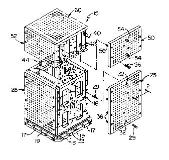
Fig. 1 illustrates a column assembly 15 which includes a
box-shaped hollow frame 16 fabricated of metal plates and having a bottom
flange 17 with peripherally spaced slots 18 and precision holes 19 for
securing the frame 16 to the table or movable pallet of a machine tool.
The slots 18 are adapted to receive screws (not shown) which are threaded
into T-nuts (not shown) located within T-slotR forlned within the machine
tool table. Preferably, Lhe colulllrl Frnrlle 16 hus a uquare horizonta1
conFiguration with each side having a width within a range between 13.25
inches and 23.25 inches. The column frame 16 may also be constructed
with diFferent heights, for exarnple, within a range between 15.5 inches
and 28 inches.
Precision base or sub-plates 25 and 26 are secured to the
side walls of the column frame 16 by a set of cap screws (not shown)
which extend through counterbored holes within the sub-plates and into
threaded holes 27 formed within the side walls of the frame 16. Each
plate 25 and 26 is precisely located with respect to the frame 16 by
a pair of dowel or locating pins 29 which extend through corresponding
~Z9~i3~
precision bushings 32 and 33 precisely inserted into the plates and
frame, respectively. Another set of cap screws 36 extend through the
vertical edge portions of the sub-plates 25 into aligned threaded holes
37 within the edge portions of the other set of opposing sub-plates
26.
As also shown in Fig. 1, the column frame 16 receives a column
extension frame 4û which mounts on top of the column frame 16 and has
the same horizontal cross-sectional configuration. The extension frame
4û is secured to the frame 16 by a set of peripherally spaced screws
1û 42 and is precisely located with respect to the frame 16 by a pair of
dowel or locating pins 44 which extend into aligned bushings 47 inserted
into the top wall of the column frame 16 and the bottom wall of the
column extension frame 4û. The vertical side walls of the extension
frame 40 receive corresponding vertical base or sub-plates 50 and 52
each of which is precisely located on the extension frame 40 by a pair
of dowel or locating pins 54 and is secured by a set of cap screws 56.
A square base or sub-plate 60 is secured to the top wall
of the extension frame 40 by a set of cap screws (not shown) and i9
precisely located by a pair of locating pinq (not shown) exter)ding inlo
aligned bushings or bores, in the same manner as the plates 50 and S2
are located and secured. The base plate 60 is also adapted to be mounted
and precisely located on the top wall of the column frame 16 by means
of the locating pins 44 and cap screws 42. As a result of the precision
location oF the column extension Frame 40 on the column frame 16 and
the precision location of each of the base or sub-plates 25, 26, 50,
52 and 60, all of the plates and the precision bores within the plates
remain in precise registration with each other.
As shown in Fig. 2, each of the base or sub-plates 25, 26,
--5--
~Z~3-~
50, 52 and 60 is provided with a precision X-Y grid pattern of alternating
threaded holes 64 and precision locating bores 66. Each of the precision
bores 66 is defined by a corresponding precision hardened bushing 68
confined within the base or sub-plate by a surrounding layer of hardenable
or epoxy material 72 in a manner as generally disclosed in above-mentioned
Patent No. 4,310,963. A hole 73 extends from the bottom of each precision
bore 66 through the base or sub-plate and is slightly smaller in diameter,
as shown in Fig. 2.
Preferably, the centerlines of the bushings 68 are located
1û within the grid pattern at distances of 2.5000 inches between adjacent
bushings, and the spacing between adjacent threaded holes 64 is the
same so that the centerline spacing between adjacent bushings 68 and
threaded holes 64 is 1.2500 inches. After all of the sub-plates are
mounted on the frames 16 and 40, each of the sub-plates 50 and 52 forms
an extension of the underlying corresponding sub-plate 25 and 26 with
the precision spacing between the bushings 68 continuing from each lower
sub-plate to the corresponding upper sub-plate. This precision spacing
results from the precision coupling of the column extension frame 40
to the column frame 16 and the precision connection of each sub-plate
to its supporting frame.
Referring to FIGS. 3 and 6, a workpiece W is clamped to a
base or sub-plate such as the grid or base plate 60 by a toggle clamp
unit 80 which includes a U-shaped sheet metal bracket 82 mounted within
a slot 83 formed within the top of a cylindrical support body 84. The
bracket is secured to the body by a pair of cross pins 86, and the body
84 has a cylindrical hole or bore 87 which receives a mating cylindrical
head portion 89 of a threaded support stud 91 which extends into a threaded
hole 64 within the base plate 60. The head portion 89 of the stud 91
supports the body 84 for rotation, and a retaining ring 93 locks the
--6--
~Z~3~
head portion 85 within the bore 87 for rotation of the body 84. The
body 84 has a transverse hole 96 (FIG. 3) which aligns with a hole 97
within the head portion 89 of the stud 91 when the body 84 is rotated
relative to stud 91 to the aligned position. In this position, a cross
pin or key (not shown) is inserted into the aligned holes 96 and 97,
and the toggle clamp unit 80 is rotated to tighten the stud 91 into
the hole 64.
In a conventional manner, the bracket 82 of the toggle clamp
unit 80 pivotally supports a bar or arm 101 by a pivot pin or rivot
102. The arm 101 carries a threaded bolt or spindle 104 which is secured
by a pair of clamping plates 106 and adjustable nuts 107. The lower
end portion of the spindle 104 carries a resilient pad 109 which is
adapted to press downwardly on a workpiece W while it is resting on
a head portion 113 of a support pin 114 extending into a bushing 68.
The bracket 82 also pivotally supports a handle 118 by a
pivot pin or rivot 119, and the handle is connected to the arm 101 by
a formed U-shaped sheet metal link 122 and a set of pivot pins or rivots
124 and 126. The toggle clamp unit 80 is movable between a retracted
or open position (FIG. 3) and a clamped position (FIG. 6) in response
to pivoting of thE~ hantile 118 between .its open position (I-~G. 3) anti
its overcenter locked position (FIG. 6).
A workpiece W may also be clamped to a base or sub-plate
such as the base plate 60 by an edge clamp asse~mbly or unit 130 (FIG5.
4, 5 and 7) which includes a cylindrical body 132 having a cyl.indrical
hole or bore 134 for receiving the head portion 89 of a threaded stud
91 in the same manner as described above in connection with the toggle
clamp unit 80. The body 132 also has a diametrically extending hole
136 (FIG. 4) which may be aligned with the hole 97 within the head portion
~Z~3-~
89 Fc)r receiving a cross pin or key to provide for threading the stud
91 i.nto a hole 64 by rotation oF the clamp body 132. After the stud
91 is tightened, the cross pin or key is removed so that the body 132
may rotate on the head portion 89 where the body is retained by the
retaining ring 93.
The edge clamp unit 130 has coplaner surfaces 138 (FIG. 4)
which form the seat for the workpiece W, as shown in FIG. 7. The surfaces
138 extend from perpendicular surfaces 141, and a slot 143 interupts
the surfaces 13B and 141. The slot 143 has undercut dovetail-shaped
tracks or recesses 144, and the slot 143 and recesses 144 extend on
an incline wi.thin the body 132. A semi-cylindrical threaded surface
147 forms the botl.om of the slot 143.
A jaw or nose member 152 has a bottom portion which mates
with the undercut recesses 144 and has a semi-cylindrical bottom
surface which cooperates with the threaded surface 147 for receiving
and adjusting set screw 154. As shown in FIGS. 5 and 7, when the screw
154 is rotated clockwise with a suitable wrench, the nose member 152
moves downwardly along the inclined undercut surfaces 144 to clamp the
workpiece W against the surfaces 138 and a serrated front surface 156
of the nose member 152. As apparerlt rronl lllo above descri.bed rotary
support incorporated as part of Ihe loggle clamp unit 80 and the edge
clamp unit 130, erlch unit i8 free to rotate on the threaded support
stud 91 so that the unit may be precisely positioned at the desired
location relative to the workpiece.
As shown in FlG. 8, it is not necessary for the rotary toggle
clamp unit 80 or the rotary edge clamp unit 30 to be mounted on a grid
base or sub-plate 60, as shown in FIG. 6 and 7. For example, the rotary
body 87 may be connected directly to a machine tool table 160 having
parallel spacecl F-slots 162 by a T-nut 164 located within the slot 162
alld receivi.ng tile threaded stud 91. A washer 166 is located between
3~953~5
the head portion 89 of the stud 91 to bridge the open top of the slot
162. The stud 91 is tightened into the nut 164 by means of a cross
pin or key extending into the aligned holes 96 and 97 within the body
84 and head portion 89 of the stud 91, as described above in connection
with FIGS. 6 and 7.
Referring to FIGS. 9 and 10, the base plate 6û or one of
the other grid plates having a precision X-Y grid pattern of threaded
holes 64 and precision bores 66 formed by the bushings 68, is adapted
to receive an angle plate 175. A square angle plate 175 is illustrated
in FIG. 9 and has a precision X-Y grid pattern of threaded holes 177
and precision bores 178 which have precisely the same spacing as the
threaded holes 64 and precision bores 66 within the base plate 60 and
other grid plates described above. The angle plate 175 is adapted to
be selectively positioned at one of a plurality of different angles
relative to the base plate 60, for example, at angles of 15, 30, 45
and 60.
As shown in FIG. 10, the angle plate 175 is provided with
a counterbored hole 182 for each of the various angles, and another
countedbored hole 182 is located within the lower corner portian of
the angle plate 175, The holes 182 are adapted to receive socket head
cap screws 183, For each of the selected angles, the angle plate 175
is also provided with a pair of precision bores 184 which align with
a corresponding pair of bores 66 within the base plate 60 at the selected
angle, A pair of locating pins 186 extends into the pair of aligned
precision bores 66 and 184 for the selected angle and precisely locate
the angle plate 175 with respect to the base plate 60, As also shown
in FIG, 9, one set of precision bores 184 is located at a uniform radius
with respect to the lowermost bore 182 so that the cap screw 183 within
~Z~5~5
the lowermost bore 182 may serve as a pivot pin for the angle plate
175 before the cap screws are tightened. After the angle plate 175
is located at a selected angle and the precision locating pins 186 are
inserted, the cap screws 183 are tightened to secure the angle plate
175 to the base plate 60.
Referring to FIGS. 11 and 12, a precision base or sub-plate
such as the base plate 60 with the X-Y gr.id pattern of threaded holes
64 and precision bores 66, may receive a pair or set of T-slot plates
such as the triangular plates 190, square plates 192 and rectangular
plates 194. Each of the plates 190, 192 and 194 has a peripherally
extending undercut recess 196 (FIG. 12) so that a combination of any
two plates properly mounted on the base plate 60 forms an inverted T-
slot 198 between the two plates. Each of the T-slot plates 190, 192
and 194 also has a plurality of counterbored holes 201 and a plurality
of precision bores 202. The spacing between the threaded holes 201
and precision bores 202 is the same as the spacing between the threaded
holes 64 and precision bores 66 within each of the base or sub-plates
descr.ibed above, and the aligned bores 66 and 202 rece.ive locating pins
such as the pins 186. The outer peripheral surfaces 203 of each of
the T-slot plates 190, 192 and 194 are precisely ground E;O that not
only may T-nuts (not shown) be used within the slots 19a, but the outer
edge surfaces of the plates may be used for precisely locating a workpiece
on the T-slot plates with respect to the base plate 60 or machine tool
table.
From the drawings and the above description, it is apparent
that the present invention provides apparatus for quickly and precisely
securing a workpiece to the table of a machine tool and further provides
for accommodating workpieces of many different sizes and shapes. The
-10-
~Z~ 5
modular fixture components or apparatus of the invention further provide
for using a precision X-Y grid pattern of threaded holes and precision
bores within a base or sub-plate so that the components may be used
with a modular Fixturing system in order to minimize the time required
to set up, locate and secure a workpiece to the machine tool table for
precision machining.
The precisionly attached base or sub-plates to the column
frame and to the extension frame shown in FIG. 1 provide for conveniently
selecting columns of various heights and with a precision X-Y grid pattern
of threaded holes and precision bores on each face or surface of the
column. In addition, the rotary clamping units sn and 130 provide for
accommodating workpieces of various conf.igurations and for quickly securing
each workpiece to a precision base plate or grid plate, and the angle
plate 175 provides for quickly and precisely position.ing a workpiece
at a selected angle relat.ive to the base or grid plate. Furthermore,
the T-slot plates shown in FIG. 11 provide for forming on a base or
support plate T-slots with precision edge surfaces to provide for quickly
locating a workpiece in addition to the infinite adjustability of clamps
secured to nuts within the T-slots 19~.
While the forms of fixturing apparatus herein described con-
st.itute preferred embodiments of the invention, it is to be understood
that the invention is not limited to these precise forms of apparatus,
and that changes may be made therein without departing from the scope
and spirit of the invention as defined in the appended claims.
The invention having thus been described, the following is
claimed:
-11-