Note : Les descriptions sont présentées dans la langue officielle dans laquelle elles ont été soumises.
1:~00939
CONNECTING DEVICES
The present invention relates to connecting devices
for use in connecting structural elements, for example,
elements of space display systems.
Various forms of such connecting elements are known
in the prior art. Australian Letters Patent No. 472753 by
Hedley Lawrence discloses a connector for tubular members,
having a bolt-type mechanism. This mechanism has the
disadvantage of requiring rotation of the structural
members themselves in order to tighten the connection and it
requires the provision of a special portion in one member
for insertion of the bolt.
Australian Patent Specification No. AU-B-38555/78
by Mero-Raumstruktur GmbH & Co. Wurzburg discloses a
different bolt connector for tubular members. This
connector can be tightened without rotation of the tubular
members to be connected, but requires that the end of one .
tubular member to be connected have a connection part welded
therein.
The necessity in these disclosures for a separate
part to be joined to both members gives rise to extra
expense and complication in their manufacture. The need to
either insert the bolt during manufacture, or else weld a
connection when the members are to be connected is
inconvenient, time consuming and wasteful of resources.
One way of overcoming this drawback is disclosed in
PCT/AU80/0019 by the Applicant. This specification
discloses a connector which is force fitted into one member,
thereby removing the need for a welded connection at one
end. However, this connector suffers from a tendency to
inadvertently disconnect at the force fitted end when
subjected to mechanical or thermal stress.
Various disclosures in the prior art show means for
clamping tubular members together. Australian Specification
No. AU-A-29209/84 is exemplary of these techniques, which
rely on an external wedge action to connect tubular members.
Such external means are not desirable where connection
3 1300~9
members for space display systems are involved, as the~ are
not visually pleasing and mar the exterior of the members to
be connected. They do not leave a smooth, uninterrupted
surface on the space display system.
It is an object of the present invention to provide
a connector which is force fitted into one of the members to
be joined and which force fitting is not readily dislodged,
yet which remains unobstrusive once in use and simple to
operate.
Another object of the present invention is to
provide an improved connector of the type disclosed in the
Applicant's PCT/AU80/0019 specification, but which has
superior resistance to mechanical and thermal stresses.
A further object is to provide a space display
system which is easily and quickly erected yet secure and
aesthetically pleasing.
The present invention utilises a deformable sleeve
member and a bolt with a widening near the head end, which
in use upon sufficient rotation interact to expand the end
of the sleeve inside one of the structural elements which
are to be connected, thereby enhancing the connection at the
force fitted end.
In a preferred embodiment the present invention
is directed to a device for connecting two hollow tubular
structural elements, a first one of said elements having
a threaded opening and a second one of said elements
having a cavity therein, comprising: a bolt having a
threaded end adapted to cooperate with the threaded
opening of the first structural element and a head end,
said bolt increasing in thickness towards said head end;
a nut member disposed on said bolt and rotationally keyed
so as to be adapted to rotate said bolt and to actually
float on said bolt; and a sleeve disposed between said
nut member and said head end of said bolt, said device
being characterised by said sleeve being adapted to be
force fitted into the cavity of said second structural
, ~ .
i300939
- 3a -
element, said sleeve being at least partially deformable;
whereby upon sufficient rotation of said bolt in the
threaded opening said bolt contacts inwardly and expands
S at least part of said sleeve outwardly to enhance the
force fitting of said sleeve in said cavity.
~..
1300~39
-- 4 --
It will be understood that the part of the sleeve
which is defo~mable may be constructed of a material which
is inherently deformable or, alternatively, may be
physically so constructed as to facilitate deformation.
Examples of the latter include the provision of one or more
slots, mere cutting of the sleeve so that it can be
deformed, or other techniques well known for producing
deformable structures.
While the invention is exemplified with respect to
force fitting into a structural element with an internally
circular cross-section, the invention is equally applicable
to elements with other internal cross-sections, with
appropriate modifications which would be apparent to one
skilled in the art. Similarly, the cross-section of the
sleeve need not be the same as the internal cross-section of
the s_ructural element. According to the instant invention,
it need only be shaped so as to expand within and contact
the inside wall of the structural element.
It also detracts in no way from the instant
invention if the widening near the head of the bolt has a
different cross-section to the portion of the sleeve which
is deformable. It is only necessary that the bolt be
capable of expanding the sleeve in such a way as to contact
the inside wall of the structural member and enhance the
force fit.
It will also be understood that the external shape
and dimensions of the structural elements to be connected
are irrelevant so long as they are consistent with enabling
operation of the connecting device according to the present
invention.
Preferably, the sleeve is longitudinally slotted
over a major part of its length so as to facilitate
expansion, and more preferably there are one or more
circumferential ribs provided with one such rib being
disposed at or near the head end of the bolt.
Preferably also, the floating nut has an inner
surface matching the outer surface of the shank of the bolt
:~300939
-- 5 --
in the region of the shank proximate the threaded end. More
preferably, said shank region includes a plurality of
circumferentially spaced, longitudinally extending ribs, and
said inner nut surface includes a plurality of
circumferentially spaced, longitudinally expanding channels
for accomodating said ribs, the arrangement then being such
that rotation of the floating nut may only be effected with
an accompanying rotation of the shank and hence the bolt as
a whole.
In order that the invention may be more fully
described and/or understood, regard is now to be had to an
embodiment of the invention with reference to the
accompanying drawings in which:-
Figure 1 is an exploded view illustrating the
various components of the connecting device;
Figure 2 is an exploded view of a preferred
embodiment of the invention; and
Figure 3 is a perspective view illustrating the
connecting device when force fitted into one of the
structural elements.
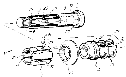
Referring to Figure 1, the connecting device -
generally designated as 1 - consists of a bolt 2, sleeve 28,
washer 4, floating nut 5 and pin 6.
The bolt 2 is characterised by a head 7, shank 8
and threaded end 9. The shank 8, at the head end, has an
inclined ramp surface 10 with the larger dimension at the
end nearest the head 7. The shank 8 also comprises a
plurality of circumferentially spaced, longitudinally
extending chanels 11 with diverging sides 12, these channels
thereby defining therebetween a plurality of tapered ribs 13
and being situated immediately 'upstream' of the threaded
end 9. One of the ribs 13 is itself slotted at 14.
The sleeve 28 consists of a main cylindrical body
15, a knurled section 16 and a plurality of longitudinally
extending slots 29.
The floating nut 5 is characterised by
longitudinally extending channels 19, 20 in both the
130Q~39
internal and external surfaces 21, 22 respectively. A small
hole 23 also extends through the nut between surfaces 21, 22
midway between a pair of adjacent channels 20. The pin 6 is
dimensioned to fit neatly through the hole 23, with the
inner end 24 adapted to come to rest in the bolt slot 14
when the device is assembled.
To connect together the structural elements using
the device is a fairly simple procedure involving, first of
all, assembly of the device, and then fixing thereof to the
10 reSpective elements.
More particularly, the sleeve 28, washer 4 and nut
5 are threaded on to the bolt in that order with the ends of
the first three elements arranged as illustrated in Figure 1
and, moreover, with the hole 23 in alignment with the slot
14 so that the pin 6 can be (and is) inserted into the hole
23. The pin 6 thus renders the nut 5 captive on the shank 8
to the extent of the travel of the pin end 24 between the~
ends 25 of the slot 14. The device is assembled thus.
One of the structural elements to be connected - in
fact, that depicted in Figure 2 as 26 - has an axial bore
into which the assembled device, and more particularly the
sleeve 28, is force fitted. At this point, it is the
knurled section 16 which provides the purchase or grip on
the wall of the axial bore. This assures, of course, that
no inadvertent rotation of the sleeve occurs. The head 7 of
the bolt 2 is of a slightly smaller diameter than the sleeve
ribs 17 so that the head and hence the bolt 2 as a whole is
free to rotate in the bore of element 26.
The other structural element (not shown), in
contrast to element 26, has a threaded aperture to receive
the bolt thread 9. With the aid of a spanner or like tool,
the bolt is screwed into said other element, utilizing the
floating nut 5 as the means of purchase for the turning
tool.
Once the thread 9 is inserted to a normally tight
state, the nut 5 may be rotated even further and the effect
of this is to deform the sleeve 28 as it rides up the ramp
i300939
-- 7 --
10, finally coming to a halt as it abuts the underside 27 of
the head 7. The deformation assumes the form of a flaring
out of the sleeve 28, permissible because of the plurality
of slots 29. This enhances the force fit relationship of
the device within element 26. It therefore becomes
considerably more difficult for inadvertent disconnection of
the element 26 from the device to take place.
Figure 2 illustrates a preferred embodiment of the
invention. The connecting device is the sam~ as previously
described except for the provision of a sleeve 3 provided
with two longitudinal slots 18 and a pair of circumferential
but interrupted ribs 17. When the connecting device is
assembled and tightened as previously described, not only
the sleeve proper but also the longitudinal ribs 17 are
deformed outwardly inside the element 26. The ribs produce
even greater enhancement of the force fit, as they are
adapted to bite into the axial bore of element 26. The
sleeve also need not be deformed so far to produce an
enchanced force fit, as the ribs 17 extend further radially
outwards than the main body of the sleeve 15.
It is to be understood that variations and/or
modifications may be made to the aforementioned disclosure
and embodiments without in any way departing from the
overall spirit and scope of the invention.