Sélection de la langue

Search

Sommaire du brevet 1301737 

Énoncé de désistement de responsabilité concernant l'information provenant de tiers

Une partie des informations de ce site Web a été fournie par des sources externes. Le gouvernement du Canada n'assume aucune responsabilité concernant la précision, l'actualité ou la fiabilité des informations fournies par les sources externes. Les utilisateurs qui désirent employer cette information devraient consulter directement la source des informations. Le contenu fourni par les sources externes n'est pas assujetti aux exigences sur les langues officielles, la protection des renseignements personnels et l'accessibilité.

Disponibilité de l'Abrégé et des Revendications

L'apparition de différences dans le texte et l'image des Revendications et de l'Abrégé dépend du moment auquel le document est publié. Les textes des Revendications et de l'Abrégé sont affichés :

  • lorsque la demande peut être examinée par le public;
  • lorsque le brevet est émis (délivrance).
(12) Brevet: (11) CA 1301737
(21) Numéro de la demande: 1301737
(54) Titre français: CRIC POUR LONGUES POUTRES
(54) Titre anglais: LONG TRAVEL BEAM JACK
Statut: Périmé et au-delà du délai pour l’annulation
Données bibliographiques
Abrégés

Abrégé anglais


ABSTRACT OF THE DISCLOSURE
A jack for supporting a ceiling beam is provided and
consists of a pair of vertical sliding support members
operated by a winch mechanism with cable which allows one
person to set the beam. The jack will lift heavy loads
eliminating the need for a crane and more manpower. In a
modification the winch handle can be operated by a foot lever
on base of the jack.
-10-

Revendications

Note : Les revendications sont présentées dans la langue officielle dans laquelle elles ont été soumises.


CLAIMS
What is claimed is:
1. A jack for supporting a ceiling beam which
comprises:
(a) a base member disposed upon a horizontal flat
surface;
(b) a first support member retained at lower end by said
base member in a vertical position;
(c) a first track member mounted transversely to upper
end of said first support member;
(d) a second support member;
(e) a second track member mounted transversely to lower
end of said second support member whereby said second track
member can travel on said first support member while said
second support member can travel within said first track
member;
(f) a plate member for carrying the ceiling beam, said
plate member being pivotally connected to upper end of said
second support member;
(g) means mounted between said first track member and
said second track member along side of said second support
member for raising and lowering said second support member;
(h) a telescoping adjustment portion slideably extending
upwardly therefrom, with said plate member pivotally connected
to the upper end of said telescoping adjustment portion, said
-7-

telescoping adjustment portion having a plurality of
vertically spaced apart apertures therethrough;
(i) a locking pin extending through said second support
member and vary of the apertures in said telescoping adjustment
portion to vary overall height of said jack;
(j) a winch mechanism suspended downwardly from said
first track member, said winch mechanism includes a spool
having a ratchet wheel formed on one flange of the spool and a
pivotable arm having a pawl engageable with the ratchet wheel
to turn the spool;
(k) a pulley suspended upwardly from said second track
member;
(1) a cable attached at one end to bottom of said winch
mechanism, extending around said pulley and winded around the
spool of said winch mechanism for raising and lowering said
second support member when said winch mechanism is manually
activated by the pivotable arm thereof;
(m) a spring biased foot lever mounted to said base
member;
(n) a plurality of rollers spaced apart and each of
which is rotatively affixed to said base member, side of said
first support member opposite from said second support member
and top of said first track member; and
(o) an elongated second cable attached at one end to
said foot lever, extending past said rollers with other end
attached to distal end of the pivotable arm of said winch
-8-

mechanism so that a person can operate said winch mechanism
by foot control.
-9-

Description

Note : Les descriptions sont présentées dans la langue officielle dans laquelle elles ont été soumises.

G R ~D i`~ S
~3~ 3~
BACKGROUND OF THE INVENTION
The instant invention relates generally to hoists and
more specifically it relates to a jack for supporting a
ceiling beam.
Numerous hoists have been provided in prior art that are
adapted to be used for lifting, positioning and installing
panels and other building material. For example, U.S. patents
numbered 2, 969,220; 3,930,645 and 4,600348 all are
illustrative of such prior art. While these units may be
suitable for the particular purpose to which they address,
they would not be as suitable for the purposes of the present
invention as heretofore described.
--1--

37
SUMMARY OF=_~@_~y~
A primary objec-t of the presen-t invention is to provide
a jack for supporting a ceiling bearn tha-t allows one person to
set the beam and which the jack will lift heavy loads
eliminating the need for a crane and more manpower.
An additional objec-t is to provide a jack for suppor-ting
a ceiling beam in which the winch handle can be operated by a
foot lever giving the person operating the jack more control
over the jackO
A further object is to provide a jack Eor supporting a
ceiling beam that is simple and easy to use.
A still further object is to provide a jack Eor
supporting a ceiling beam that is economical in cost to
manuEacture.
Further objects of th~ invention will appear as the
description proceeds.
To the accomplishment o:E the above and related objects,
this invention may be embodied in the form illustrated in the
accompanying drawings, attention being called to the fact,
however, that the d.rawings are illustrative only, and that
changes may be made in the speciflc construction illustrated
and described within the scope of -the appended claims.

~3~7;~7
BRIFF DESCRIPTION OF T~E DRAWING FIGURES
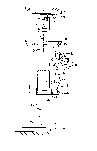
Figure 1 is a side elevational view of the invention
with par-ts broken away.
Figure 2 is an enlarged front view of the winch
mechanism in greater detail as indicated by arrow 2 in Figure
1.
Figure 3 is an enlarged cross sectional view taken along
line 3-3 in figure 1 showing the lower track member in greater
detail.
Figure 4 is a side elevational view of a modification
with parts broken away in which the winch handle is operated
by a foot lever attached to an operating cable with rollers.

~1.3~737
DETAILED DESCRIPTION
Turning now descriptively to the dra~ings, in which
similar reference characters denote similar elements
throughout the several views, Figures 1, 2 and 3 illustrate a
jack 10 for supporting a ceiling beam 12 consisting of a base
member 14 disposed upon a horizontal flat surface, such as a
floor 16. ~ first support member 18 is retained at lower end
20 by the base msmber 14 in a vertical position. A first
track member 22 is mounted transversely to upper end 24 of the
first support member 18. A second support member 26 is
provided with aa second track member 28 mounted transversely
to lower end 30 of the second support member 26. The second
track member 28 can travel on the first support member 18
while the second support 26 can t~avel within the first track
member 22. A plate member 32 is for carrying the ceiling beam
12. The plate member is pivotly connec-ted at 34 to upper end
36 of the second support member 26. A device 38 mounted
between the first traclc member 22 and the second track member
28 along side of the second support member 26 for raising and
lowering the second support member.
The second support member 26 further contains a
telescoping adjustment portion 40 slideably extending upwardly
therefrom, with the plate member 32 pivotly connected at 334
to -the upper end 36 of the telescoping adjustment portion 40.
The telescoping adjustment portion has a plurality of
vertically spaced apart apertures 42 therethrough. A locking

131)~7
pin 44 extends through the second support member 26 and any of
the aper-tures 42 in the telescoping adjustment portion 40 very
overall height of the jack 10.
The device 38 contains a winch mechanism 46 suspended
downwardly by hook 48 from flange 50 of the first track member
22. The winch mechanism 46 includes a spool 52 that has a
ratchet wheel 54 formed on one flange of the spool 52 and a
pivotable arm 56 that has a pawl 58 engageable with the
ratchet wheel 54 to turn the spool 52. ~ pulley 60 is
suspended upwardly by hook 62 from flange 64 of the second
track member 28. A cable 66 is attached at one end 68 to
bottom 70 of the winch mechanism 46, extends around the pulley
60 and winded around the spool 52 of the winch mechanism for
raising and lowering the second support member 26 when the
winch mechanism 46 is manually activated by the pivotable arm
56 thereof.
As shown in Figure 4, the jack 10 can further contain a
sprin~ biased foot lever 72 mounted to the base member 14 at
74. A plurality of rollers 76 are spaced apart and each of
which is rotatably affixed to the base member 14, side of the
first support member 18 opposite from the second support
member 26 and the top of the first track member 22. An
elongated second cable 78 is attached at one end 80 to the
foot lever. extending past the rollers 76 with other end 82
attached to distal end 84 of the pivotable arm 56 of the winch
mechanism 46 so that a person can operate the winch mechanism
by foot control.
--5--

~0~7"
While certain novel features of this invention have been
shown and described and are pointed out in the annexed claims,
it will be understood that various omissions, substitutions
and changes in the forms and details of the device illustrated
and in its operation can be made by those s~illed in the art
without departing from the spirit of the invention

Dessin représentatif
Une figure unique qui représente un dessin illustrant l'invention.
États administratifs

2024-08-01 : Dans le cadre de la transition vers les Brevets de nouvelle génération (BNG), la base de données sur les brevets canadiens (BDBC) contient désormais un Historique d'événement plus détaillé, qui reproduit le Journal des événements de notre nouvelle solution interne.

Veuillez noter que les événements débutant par « Inactive : » se réfèrent à des événements qui ne sont plus utilisés dans notre nouvelle solution interne.

Pour une meilleure compréhension de l'état de la demande ou brevet qui figure sur cette page, la rubrique Mise en garde , et les descriptions de Brevet , Historique d'événement , Taxes périodiques et Historique des paiements devraient être consultées.

Historique d'événement

Description Date
Inactive : Demande ad hoc documentée 1995-05-26
Le délai pour l'annulation est expiré 1994-11-26
Lettre envoyée 1994-05-26
Accordé par délivrance 1992-05-26

Historique d'abandonnement

Il n'y a pas d'historique d'abandonnement

Titulaires au dossier

Les titulaires actuels et antérieures au dossier sont affichés en ordre alphabétique.

Titulaires actuels au dossier
WESLEY A. GORDON
GEORGE SPECTOR
Titulaires antérieures au dossier
S.O.
Les propriétaires antérieurs qui ne figurent pas dans la liste des « Propriétaires au dossier » apparaîtront dans d'autres documents au dossier.
Documents

Pour visionner les fichiers sélectionnés, entrer le code reCAPTCHA :


Pour visualiser une image, cliquer sur un lien dans la colonne description du document (Temporairement non-disponible). Pour télécharger l'image (les images), cliquer l'une ou plusieurs cases à cocher dans la première colonne et ensuite cliquer sur le bouton "Télécharger sélection en format PDF (archive Zip)" ou le bouton "Télécharger sélection (en un fichier PDF fusionné)".

Liste des documents de brevet publiés et non publiés sur la BDBC .

Si vous avez des difficultés à accéder au contenu, veuillez communiquer avec le Centre de services à la clientèle au 1-866-997-1936, ou envoyer un courriel au Centre de service à la clientèle de l'OPIC.

({010=Tous les documents, 020=Au moment du dépôt, 030=Au moment de la mise à la disponibilité du public, 040=À la délivrance, 050=Examen, 060=Correspondance reçue, 070=Divers, 080=Correspondance envoyée, 090=Paiement})


Description du
Document 
Date
(aaaa-mm-jj) 
Nombre de pages   Taille de l'image (Ko) 
Abrégé 1993-10-29 1 12
Revendications 1993-10-29 3 62
Dessins 1993-10-29 1 34
Dessins représentatifs 2003-03-11 1 6
Description 1993-10-29 6 134