Note : Les descriptions sont présentées dans la langue officielle dans laquelle elles ont été soumises.
l~es cr i pt i o n ~ 6~
~ethod for the control of the dispatch of elevator cars from the
main stop during upward peak traffic.
The invention relates to a method for the control of the dispatch
of elevator cars from the main stop of an elevator group consisting
of at least one elevator, where the dispatch of the elevator cars
from the main stop during upward peak traffic takes place in depen-
dence (or as a function) of a dispatch interval, which can be
matched to the fluctuating passenger traffic.
A dispatch control for an elevator group consisting of several
elevators is known according to European patent - A3 0 030 163,
in which the dispatch interval is based on an approximate round
trip time (RTT) of an elevator car or on a mean round trip time,
which results from the three preceding, approximate round trip
times. The round trip time is divided by the number of elevator
cars taking part in the servicing of the main stop. From this
results a mean dispatch time interval. The approximate round trip
time is the expected time, which the elevator car requires for the
upward trip, the servicing of the car calls registered at the main
stop and the return trip to the main stop and is calcuated from
tlle building parameters, the installation parameters and condition
parameters. In case the elevator car exhibits less than half the
nominal load after expiration oE the calculated interval time,
there takes place,in function of thè cars available at the main
stop, a shortening of the calculated interval time. In case the
elevator car exhihits, after expiration of the calculated inter-
val time, at least half the nominal load, the calculated interval
time is shortened in a similar manner, however, with a different
weighting of the available cars.
The disadvantage of this known control resides in the fact~ that
the present (or actual) dispatching interval time is determined
on the basis of approximate round trip times calculated from data
of the past. This permits J in the best case, to estimate the
dispatching interval necessary for the coverage of the actual traf-
fic requirements (?). A further drawback is the fact, that the
... .. . . ...
~3~ G8
--2--
1 control differentiates (or distinguishes) only between a
departure load, being smaller than half the nominal load and
a departure load which is at least equal to half the nominal
load~ and in doing so shortens the interval time based on
the (number of~ cars available at the main stop. From this
there results again an approximate matching with the
effective variations of the traffic requirements.
Consequence of both drawbacks is a not optimal utilization
of the elevator cars.
It is here, that the invention tries to provide a remedy.
As characterized in the claims, the invention solves the
problem to create a method, in which the offer of
transportation is matched to the demand for transportation
at the main stop of an elevator installation.
The advantages realized by the invention can be seen
essentially in the fact, that the passengers of the
elevators, thanks to the variable conveying capacity of the
elevators, are profiting from a service friendly to the
user. The car loading matched to the upward-peak-traffic
make a smooth tra~`fic flow at the main stop possible.
Accordingly in one of its aspects this invention resides in
providing a method for the control of the dispatch of
elevator cars, during up peak traffic conditions from a main
stop or floor of an elevator group having at least one
elevator, co~prising the steps of detecting building filling
passenger traffic arriving at a main floor by a first
traffic measurement and detecting building filling passenger
traffic departing at the main floor by a second traffic
measurement; creating data fields by storing predetermined
data related to transport capacities, nominal departure
. ~
~5 '
.
96~
- a-
1 loads and nominal time intervals calculated according to an
algorithm; establishing nominal values of a departure load
variable and a time interval variable dependent on said
first and second traffic measurements and dependent on said
predetermined data stored in said da~a fields and calculated
according to said algorithm; and comparing an actual value
of a departure load for each elevator car with said nominal
departure load variable value established in said step c and
comparing an actual time interval with said nominal time
interval variable value established in said step c and, upon
at least one of said actual values reaching said compared
nominal value, dispatching an associated elevator car from
the main floor.
In another aspect this invention resides in providing an
apparatus for controlling the dispatch of at least one
elevator car during up peak traffic conditions from a main
floor comprising a first sensor for generating a first
traffic measurement signal representing building filling
passenger trafEic arriving at a main floor; a second sensor
for generating a second trafic measurement signal
representing building filling passenger traffic departing at
the main floor; means defining data fields for storing
predetermined data related to transport capacities, nominal
departure loads and nominal time intervals calculated
according to an algorithm; means for storing said algorithm
and for calculating nominal values of a departure load
variable and a time interval variable dependent on said
first and second traffic measurement signals and dependent
on said predetermined data stored in said data fields; and
means connected to said first and second sensors, said means
for storing and for calculating, and said means defining
data fields for comparing an actual value of a departure
load for an associated elevator car with said calculated
nominal departure load variable value and for comparing an
~3~ 96~
-2b-
1 actual time interval with said calculated nominal time
interval variable value and, upon at least of one said
actual values reaching said compared nominal value,
dispatching said associated elevator car from the main
floor.
In a preferred aspect the transport capacities are
calculated according to an equation
TC = CFl-SL
.
1 + NOF(l ~ (( NOF - 1 ) /NOF ) SL )
wherein CFl is a predetermined calibrating factor one, SL is
said nominal departure load variable and NOF is a number of
floors serviced by the associated elevator cars of an
elevator group.
In a further aspect tllis invention resides in providing an
apparatus for controlling the dispatch of elevator cars of
an elevator group having at least on elevator, during up
peak traffic conditions, from a main floor comprising a call
registering device for generating a first traffic
measu~ement signal as a destination calls variable
representing building fi~ling passenger traffic arriving at
a main floor; a load measuring device for generating a
second traffic measurement signal as an actual departure
load variable representing building filling passenger
traffic departing at the main floor; means for creating data
fields by storing predetermined data related to transport
capacities nominal departure loads and nominal time
intervals calculated according to an algorithm; means for
calculating nominal values of a departure load variable and
a time interval variable dependent on said destination calls
variable and said actual departure load variable and
dependent on said predetermined data stored in said data
,~
~y~
13~J~IL96~
-2c-
.
1 flelds, and calculated according to said algorithm; and
means connecting said call registering device, said load
measuring device, said means for creating data fields and
said means for calculating for comparing an actual value of
a departure load for each elevator car with said nominal
departure load variable value and comparing an actual
interval with said nominal time interval variable value and
upon at least one of said actual values reaching said
compared nominal value, dispatching an associated one of
said elevator cars from the main floor.
The invention will be explained in more detail in the
following with the aid of drawings illustrating only one way
of execution. Shown are in:
Figure 1 a schematic presentation of the elevator group
participating in the method (and) consisting of
the elevators l; 2 ..... n,
20 figure 2 a schematic presentation of the data sources
and data sinks,
figure 3 a flow chart of an algorithm for the dispatch
of the elevator car pertaining to the elevator
group,
figure 4 a flow chart of the algorithm for the
determination of the traffic requirement and
30 table 1 a listing of the constants, status variables,
variables and field variables involved in the
method.
To assure a better survey (or review) the name of the algorithm
,,~ ; i
~u~
-3-
1 and the names of the devices of the figures 1, 2, 3 and 4 as well
as the abbreviations of the constants, status variables, variables
and field variables quoted in the column ~Memo-Code~ of the table
1, are used as reference symbols. In the figures 1, 2, 3 and 4
reference symbols with and wikhout indices are used. Not indexed
reference symbols refer to elevator groups consisting of n eleva-
tors. Reference symbols indexed with .1; .2 ... ~n refer to the
elevators l; 2 ... n. A reference symbol indexed with .x refers
to one of the elevators l; 2 ...n. Steps are presented in the
figures 3 and 4, in which it is examined, whether constants, status
variables or variables satisfy the triangularly shaped framed con-
ditions positively or negatively. A positive result of an examina-
tion (or test) is characterized with the reference symbols J, a
negativ~ result of an examination (or test) is characterized with
the reference symbol N in each respective step of examination.
Presented in figure 1 is an elevator group consisting of the ele-
vators l; 2 ...n~ A conveying machine designated with MOTOR.l
drives an elevator car CAR.l of the elevator 1. The conveying
machine MOTOR.l is supplied with electrical energy by a drive
system SYSTEM.l, which is controlled by an elevator control
CONTROL.1.
For the detection of the building-~filling passenger traffic depart-
ing at a main stop MAINSTOP, load measuring devices or passenger
counting devic~s are provided as execution variants of a sensor
SENSOR.1 arranged on the elevator car CAR.1. The SENSOR.1 is in
connection with the elevator control CONTROL.1. The elevators
2; 3 ... n with the conveying machines MOTOR.2;~MOTOR.3... MOTOR.n,
drive systems SYSTEM.2; SY~TEM.3... SYSTEM.n, elevator controls
CONTROL.2; CONTROL.3... CONTROL.n, sensors SENSOR,2; SENSOR.3...
SENSOR.n and the not shown elevator cars CAR.2; CAR.3... CAR.n
correspond in their construction and in their mode of functionung
to elevator 1. A sensor designated by SENSOR detects at the main
stop M~INSTOP the arriving building-filling passenger traffic. A
process computer COMPUTER is in connection with the elevator con-
trols CONTROL.l; CONTROL.2-.. CONTROL.n9 with the sensor SENSOR
and with an input~output unut TERMINAL. An algorithm CONTROLLER
.
~3~3L96~3
--4--
l implemented in the process computer COMPUTER c~ntrols the dispatch
of the elevator cars CAR.l; CAR.2... CAR.n.
Presented in figure 2 are the algorithm CONTROLIER implemented in
the process computer COMPUTER and the data sources and data sinks
participating in the method (or process). Provided at the main
stop MAIN6~OPforthe detection of the arriving building-filling
passenger traffic are, as variants of embodiment of the sensor
SENSOR, light barriers, turnstiles, infrare~ detectors,
field detectors or call registering devices. The building-filling
passenger traffic originating from (or at) the main stop M~INSTOP
is detected by sensors SENSOR.l; ~ENSOR.2... ~ENSOR.n arranged on
the elevator cars CAR.l; CAR.2... CAR.n and passed on to the ele-
vator controls CONTROL.l) CONTROL.2,.. CONTROL.n. Constants re-
quired in the method (or process) can be chosen freely (or at ran-
dom) and are communicated to the algorithm CONTROLLER by means of
the input/output unit TERMIN~L. Destination calls DCL detected by
the sensor SENSOR and actual departure loads LFB.1; LFB.2...LFB.n
are inputted to the algorithm CONTROLT~R and processed further.
The constants calibrating factor l CFl, calibrating factor 2 CF2,
calibrating factor 3 CF3, calibrating factor 4 CF4, calibrating
factor 5 CF5, calibrating factor 6 CF6, nominal load LCC, minimum
transport capacity MTC, number of elevators NOC, number of floors
NOF, passenger access basis PAB can be chosen freely (or at random)
by way o the input~output unit TER~5IN~L. The elevator controls
CONTROL.l; Co~rRoL.2... CONTROL-n generate the status variables
elevator start CS.1;CS.2,.. CS.n, data inquiry DR.l; DR.2... DR.n
according to the algorithm CONTROLL~R and receive from the algo-
rithm CONT~OLLER the status variables door closing command DC.l;
DC.2... DC.n.
In a first step sequence the algorithm CONTROLT~R creates a trans-
port capacity field TCA and an interval field IVA. In a first cycle
through the first step sequence a transport capacity TC and
a nominal time interval IV is determined as a function of the nominal
departure load ~L~ where the value of SL is equal to one. The
value of the calculated transport capacity TC, and the
,. ~
~ s
~3~9~
--5--
1 calculated nominal time interval IV are deposited in a field compo-
nent of the transport capacity field TCA and the interval field
IVA respectively, the field component being represented by the symbol
[ ]. The symbol ": =" signifies an assignment
of the value on the right side of the symbol to the variable on
the left side of the s~mbol. In the further cycles of the first
step sequence SL is increased in each case by one. The first
step sequence is repeated, until Sl has reached the value of the ncminal or
rated load constant LCC. In a second step sequence of th~ algorithm CO~OLLER
prepares (or edits) the data necessary for the control o~ the dispatch. In
this a traffic requirement UT i5 determined as function of the des-
tination calls DCL received from the sensor SEN6OR and a traffic
requirement ~T is determlned as function of the actual departure loads
LFB.x of the c~r to be accessed (CAR.x), as received from the elevator
control CONTROL.x. 6ubsequently the algorithm CONTROLLER calculates
from the highe~- of the two traffic requirements ~T the traffic ca-
pacity TC and checks, whether the value of TC is greater than or 2qual to
the minimum transport capacity MT~. The nominal depar-
ture load SL, correspondi.ng to the transport capacity TC deter-
mined from the traffic requirement ~JT,is established from the trans-
port capaci~y field ~CA. The determination o~ the nominal time
int~rval IV takes place in an analogous manner. In a third step
sequence the algorithm CONTR~LLER evaluates the now known data for
the control of the dispatch. The actual departure load I,FB.x is com-
pared with the nominal departure load SL, until equality prevailsbetween the actual and the nominal values. ~imultaneousl~ a compa-
rison is made between an actual time interval IT and the nominal
time interval IV. ~n OR-operator links both conditions, so that
either at equality of LFB.x - SL or at equality IT = IV the door
closing command DC.x is generated to the elevator control CONTROL.x,
~hich (then) dispatches the boarding car (CAR.x).
Figure 3 shows the structure and the sequential course of the algo-
rithm CONTROLLER. In a step ~ 1 all constants and variables used
in the algorithm CONTROLLER are brought once in known manner into
the initial state. In step S2 an iteration procedure comprising
~3~
l the steps S3; S4... S6 for the computation of the transport capa-
city TC and the nominal time interval IV as well as for the crea-
tion of the data ~ields~ transport capacity field TC~ and interval
field IVA, is carried out. In a first cycle ofthe iteration ~oce-
dure shown in the step S2, the value of the nominal departure
load SL is set to one, in a second cycle to
two and so on, until the iteration procedure has been cycled (or
run through) LCC-times. In step S3 the transport capacity TC is
calculated as function of the nominal departure load SL. The cal-
culation o~ the inclusive acceleration-deceleration-, door- and
exiting losses is estimated at "m" seconds. From the num'~er of
stops and the stopping times the round trip time can be calculated.
The formula used in step S3 for the calculation of the transport
capacity TC results from the relation transport capacity = departure
load/round trlp time. Carried out in step S4 as a function of the
calibratin~ factor 2 CF2, the nominal departure load'SL, the trans-
port capacity TC and the number of elevators NOC, is the calculation
of the nominal time interval IV. In the step ~5 and in the step
S~, the transport capacity TC calculated in step S3 and the nominal
time interval IV calculated in step S4 respectively are deFosited in
the transport capacity field TC~ an~ in the interval field IVA
respectively. In this t~e calculated v~lues are assigned at every cycle of
the iteration procedure to the field components indexed with SL OL
the one dimensional data fields.
The control loop starts with the step S 7, in which it is checked,
whether the status variables elevator start C~.l; CS.2.., Cs.n lir~ecl
with the OR-operator "V" and generated from the elevator controls CONTROL.l;
CON~ROL.2... CON~ROL.n, have a value of one. A positive result of the
check justifies the start of the actual time interval IT shown in
step S8. In step S9 it is checked, whether data are requested from
one of the elevator controls CONTROL.l; CONTROL.2... CO~ROL.n b~
means of the status variable data inquiry DR.l; DR.2... DR.n. In
this the data requesting elevator control CONTROL.x is identified.
Thereby the algorithm CONTROLLER identifies the index of the actual
departure load LFB.x to be received in later (or subsequent)
steps and the door closing command DC.x to be generate~ in later
t` `~\ .
.
~3~1L9Ç~
--7--
1 (or subseq~ent) steps. A positive result of the check justifies
the execution of the steps ~ 10; S 11... S 2S explained in figure
4, in which the traffic requirement UT is determined independently
of the building filling passenger traffic. The traffic capacity
TC is calculated in step S 29 from the calibrating factor 5 CF5
and the traffic requirement UT determined by the method shown in
Figure 4. The transport ~apacity TC, dependent on the traffic requirement UT,
is checked in step ~30, as to whether it equals or exceeds the minimum transpo~t ca-
pacity MTC. A negative result of the chec~ justifies the execution
of the step S 39, I.lherein predetermined values of one and infinity are
assigned to the nominal departure lo~ L and to the nominal time interval rv
respectively. After conclusion of step S39 the algorithm CONTROLLER continues the
control cycle in a step S36. A positive result of the check performed
in step S30 justifies the execution of the step sequence S 31; S 32...
S 38. In step S31 the nominal departure load ~L is reset
to zero. In a first cycle of the iteration proce-
dure presented in the step S32 and the step S33, the nomi-
nal departure load SL is set to one and the field componentis indexed
with ~L. The transport capacity field TCA is compared with the trans-
port capacity TC, calculated on the basis of the traffic require-
ment ~T. At every cycle of the iteration procedure, the nominal
departure load SL made into the running variable is increased by
one and there~y the selected field component indexed with SL.
The iteration procedure of the step S32 is repeated, until
the transport capacity TC deposited in the transport capa~ity field
TCA corresponds to the transport capacity TC calculated on the basis
of the traffic requirement UT. In step S34 the field component in-
dexed with ~L is the interval field IVA which is addressed and the c~
ponent value assigned to the variable nominal time interval IV.
The nominal time interval IV addressed onthe basis of the departure
load SL, determined in the interval field IVA in steps ~ 32 and
S 33~is calibrated in the step 35 with the calibrating factor 6
CF6. The iteration procedure shown in step S 36 checks in step S37
the actual departure load LFB.x of the access car (C~R.x) and the
actual time interval IT, until either the actual departure
load LFB.x is equal to the nominal departure load ~L or the actual
time interval IT is equal to the nominal time interval IV.
:~L3~3~;~
1 As soon as either one of the two conditions is satisfied,
the door closing command DC.x is ~enerated in step S38 to the
elevator control CONTROL.x, which dispatches the access car (CAR.x).
Thereby a control cycle of the algorithm CONTROLLER ls terminated.
Figure 4 sho~s the structure and the flow chart of the algo-
rithm CONTROLLER for the determination of the traffic requirement
UT. In the steps S10; Sll... S14 the variables necessary for the
determination of the traffic requirement UT are prepared, by re-
seting in the step ~10 and Sll the variable boardi.ng passenger calls
PCL and the variable boarding passengers PCA to zero. In step S12
the algorithm CONTROLLER receives the destination calls DCL de-
tected by the sensor SENSO~. Assigned in step S13 and S14 to the
variables destination c~lls ALT DCLALT and actual-departure load
ALT LFB.xALT used for the detection of the traffic requirement UT,
are the)at the start of the detection actual destination calls
DCL and the, at the start of the detection actual, actual-departuLre
load LFB.x. The detection of the traffic requirement UT is ini-
tiated in step S15 with th~ start of the passenger access time P~T.
Carried out in the step S16 is an iteration procedure comprising the
steps S17; S18... S24 for tlle detection of changes, with respect to
destination calls DCL and the actual departure load LFB.x, having
occurred during the access time PAT. In a first cycle of the itera-
tion procedl~re i~lustrated in ste.p S1.6, the destination calls
are received in step S17 and a call difference DDC calculated
in step Sl~ from the actual destination calls DLC and the old desti-
nation calls DCI.ALT. Subsequently the actual destination calls
DCL are assigned to the old destination calls DCLALT in step sl9.
In step S20 the call difference DDC is summed up to the already de-
tected koarding passenger calls PCL. In the steps S21; S22... S24
a cycle (or run) is presented, which is identical with the run sho~n
in the steps S17; S18... S20 and in which essentially a passenger
access difference LD is calculated and this (or the same~ is summed
up to the already detected boarding passengers PCA. The iteration
procedure illustrated in step 16 is cycled until either the
koarding passenger calls PCI, or the boarding passengers
PC~ have reached the value of the passenger access basis PAB
~L3~3~9~
1 received from the input/output unit TERMINAL. With the step
S25 the detection of the traffic requirement UT is
concluded. In steps S26 it is checked, whether during the
passenger access time PAT more boarding passenger calls PCL
were detected than boarding passengers PCA. A positive
result of the check justifies execution of the step S27, in
which the traffic requirement UT i5 pre-calculated, for
example for five minutes, from the passenger access calls
PCL and passenger access time P~T. A negative result of the
check of step S26 justifies execution of step S28, in which
the trafEic requirement is pre-calculated, for example for
five minutes, from the boarding passengers PCA and the
passenger access time PAT. After conclusion of the step S27
or S28 the algorithm CONTROLLER continues with the control
loop at step S29.
Although the algorithm shown in Figs. 2 4 has been described
in terms of a computer program for a general purpose
programmed computer, it also could be implemented in
discrete analog or digital circuitry. Each o~ the
arithmetic and comparison functions can be performed by
circuit elements which are well known. The present
invention combines these known arithmetic and comparison
functions into a new and unique method and apparatus for
controlling the dispatch of elevator cars from a main floor,
particularly during up peak traffic conditions.
In accordance with the provisions of the patent statutes,
the present invention has been described in what is
considered to represent its preferred embodiment. However
it should be noted that the invention can be practiced
otherwise than as specifically illustrated and described
without departing from its spirit or scope.
t'~
,, .
~3~
--10--
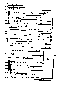
Table 1
Memo-Code Constant
CFl calibrating factor 1
CF2 calibrating factor 2
CF3 calibrating factor 3
CF4 calibrating factor 4
CF5 ca].ibrating factor 5
CF6 calibrating factor 6
LCC nominalload (or rated load)
MTC minimum transport capacity
NOC number of elevators
NOF number of floors
PAB passenger access basis
Memo-Code Status variable
_
CS elevator start
DC door closing command
DR data inquiry (or request)
~ Memo-Code variabl-
DCL destination calls
DDC call difference
IT actual-time interval
IV nominal-time interval
LD passenger access (or boarding)diff
LFB actual-departure load
PAT passenger access(or boarding) time
PCA accessing(or boarding)passengers
PCL accessing(or boarding)passeng.calls
SL nominal-departure load
TC transport capacity
UT traffic requirement
Memo-Code field variable
3S - -
IVA interval field
TCA transport capacity field