Sélection de la langue

Search

Sommaire du brevet 1308460 

Énoncé de désistement de responsabilité concernant l'information provenant de tiers

Une partie des informations de ce site Web a été fournie par des sources externes. Le gouvernement du Canada n'assume aucune responsabilité concernant la précision, l'actualité ou la fiabilité des informations fournies par les sources externes. Les utilisateurs qui désirent employer cette information devraient consulter directement la source des informations. Le contenu fourni par les sources externes n'est pas assujetti aux exigences sur les langues officielles, la protection des renseignements personnels et l'accessibilité.

Disponibilité de l'Abrégé et des Revendications

L'apparition de différences dans le texte et l'image des Revendications et de l'Abrégé dépend du moment auquel le document est publié. Les textes des Revendications et de l'Abrégé sont affichés :

  • lorsque la demande peut être examinée par le public;
  • lorsque le brevet est émis (délivrance).
(12) Brevet: (11) CA 1308460
(21) Numéro de la demande: 1308460
(54) Titre français: APPAREIL DE REGLAGE DU SYSTEME DE COMMANDE DU MOTEUR ET METHODE CONNEXE
(54) Titre anglais: APPARATUS AND METHOD FOR ADJUSTING ENGINE CONTROL SYSTEM
Statut: Périmé et au-delà du délai pour l’annulation
Données bibliographiques
(51) Classification internationale des brevets (CIB):
  • F02D 41/02 (2006.01)
  • F02D 41/24 (2006.01)
  • F02D 41/26 (2006.01)
(72) Inventeurs :
  • FUJISAWA, MASAAKI (Japon)
(73) Titulaires :
  • HITACHI, LTD.
(71) Demandeurs :
  • HITACHI, LTD. (Japon)
(74) Agent: KIRBY EADES GALE BAKER
(74) Co-agent:
(45) Délivré: 1992-10-06
(22) Date de dépôt: 1987-09-30
Licence disponible: S.O.
Cédé au domaine public: S.O.
(25) Langue des documents déposés: Anglais

Traité de coopération en matière de brevets (PCT): Non

(30) Données de priorité de la demande:
Numéro de la demande Pays / territoire Date
231183/86 (Japon) 1986-10-01

Abrégés

Abrégé anglais


ABSTRACT OF THE DISCLOSURE
A novel adjustment apparatus for an engine
control system is disclosed, in which a compensation
amount applied from the adjustment apparatus separate
from the engine control unit is stored in a compensation
amount memory unit which is capable of rewritten and
has the written data therein not capable of being
erased.

Revendications

Note : Les revendications sont présentées dans la langue officielle dans laquelle elles ont été soumises.


CLAIMS:
1. An adjustment device for controlling an operation
parameter of an apparatus, comprising:
manually settable compensation amount determining
means for producing a compensation amount signal representing
an amount of compensation of a control value used in
controlling said operation parameter;
mode decision means for selectively producing a mode
signal indicating an adjustment mode or a normal mode; and
control means connected to said manually settable
compensation amount determining means and said mode decision
means for producing a control output signal for controlling
said operation parameter based on a control value corrected by
a compensation value, including memory means for storing a
compensation value, and processing means for:
(a) storing in said memory means a compensation
valued based on said compensation amount signal and producing
said control output signal based on said compensation value
when said mode signal indicates an adjustment mode, and
(b) producing said control output signal based on a
compensation value previously stored in said memory means and
without regard to said compensation amount signal when said
mode signal indicates a normal mode.
2. The adjustment device according to claim 1, wherein
said manually settable compensation amount determining means
comprises a potentiometer.
-9-

3. The adjustment device according to claim 1, wherein
said mode decision means comprises a manually operable switch
connected to a signal source.
4. An adjustment device for controlling an operation
parameter of an apparatus, comprising:
manually settable compensation amount determining
means for producing a compensation amount signal representing
an amount of compensation of a control value used in
controlling said operation parameter;
mode decision means for selectively producing a mode
signal indicating an adjustment mode or a normal mode; and
control means connected to said manually settable
compensation amount determining means and said mode decision
means for producing a control output signal for controlling
said operation parameter based on a control value corrected by
a compensation value, including memory means for storing a
compensation value, and processing means for:
(a) storing in said memory means a compensation
value based on said compensation amount signal and producing
said control output signal based on said compensation value
when said mode signal indicates an adjustment mode, and
(b) producing said control output signal based on a
compensation value previously stored in said memory means and
without regard to said compensation amount signal when said
mode signal indicates a normal mode;
wherein said memory means includes a first memory
and a second memory, and further including memory command
means for generating a command signal to indicate to said
-10-

processing means that a predetermined condition of said
apparatus has been reached, said processing means being
responsive to said mode signal indicating said adjustment mode
for storing said compensation value based on said compensation
amount signal in said first memory and for shifting said
compensation value from said first memory to said second
memory upon receipt of said command signal, and said
processing means being responsive to said mode signal
indicating said normal mode for producing said control output
signal based on a compensation value stored in said second
memory.
5. An adjustment apparatus for an engine control
system, comprising:
first memory means for storing a control program and
fixed control values;
second memory means, of a type in which data can be
rewritten and stored in a non-volatile manner, for storing
compensation values;
third memory means for temporarily storing
compensation values;
control means connected to said first, second and
third memory means for generating a control output signal to
perform a predetermined engine control processing according to
(i) the control program and a fixed control value stored in
said first memory means and (ii) a compensation value stored
in said second memory means, including:
-11-

(a) mode decision means for producing a mode signal
indicating an adjustment mode for correcting a compensation
value;
(b) compensation amount determining means for
producing a compensation amount signal representing an amount
of compensation for a control value;
(c) memory command means for generating a command
signal to indicate that a predetermined engine condition is
reached; and
(d) processing means connected to said mode decision
means and said compensation amount determining means for
storing in said third memory means a compensation value based
on a compensation amount signal received from said
compensation amount determining means when said mode signal
indicating an adjustment mode is received from said mode
decision means and for transferring a compensation value from
said third memory means to said second memory means when said
command signal is received from said memory command means
while said mode signal indicates an adjustment mode.
6. The adjustment apparatus according to claim 5,
wherein said compensation amount determining means comprises a
manually adjustable potentiometer.
7. The adjustment apparatus according to claim 5,
wherein said mode decision means comprises a manually operable
switch connected to a signal source.
8. The adjustment apparatus according to claim 5,
wherein said memory command means comprises a manually
operable switch connected to a signal source.
-12-

9. A method of controlling adjustment of an operation
parameter of an apparatus, comprising the steps of:
(a) continuously producing a compensation amount
signal representing an amount of compensation of a control
value used in controlling said operation parameter by means of
a manually adjustable device;
(b) calculating a compensation value from said
compensation amount signal during an adjustment mode period of
time;
(c) storing said compensation value in a memory
device; and
(d) during a normal mode of operation following said
adjustment mode period of time, generating a control signal
for controlling said operation parameter based on a
compensation value stored in said memory device and without
regard to said compensation amount signal.
10. A tamper-proof adjustment device for controlling an
operation parameter of an apparatus, comprising:
a detachable control amount determining unit
including manually settable means for producing a control
amount signal representing an amount of a control value used
in controlling said operation parameter; and
control means selectively connectable to said
control amount determining unit for producing a control output
signal for controlling said operation parameter based on a
stored control value, including means for determining a
control value from a control amount signal received when said
control amount determining unit is attached to said control
-13-

means, means for storing the control value determined by said
determining means and means for producing said control output
signal based on the control value stored in said storing means
when said control amount determining unit is detached from
said control means.
11. A tamper-proof adjustment apparatus for an engine
control system for controlling an operation parameter thereof,
comprising:
a manually settable and detachable compensation
amount determining unit including means for producing a
compensation amount signal representing an amount of
compensation of a control value used in controlling said
operation parameter; and
control means connectable to said manually settable
and detachable compensation amount determining unit for
producing a control output signal for controlling said
operation parameter based on a control value corrected by a
compensation value, including memory means, of a type in which
data can be rewritten and stored in a non-volatile manner, for
storing a compensation value determined from a compensation
amount signal received from said manually settable and
detachable compensation amount determining unit and processing
means for:
(a) storing in said memory means a compensation
value based on said compensation amount signal and controlling
said control means to produce said control output signal based
-14-

on said compensation value when said manually settable and
detachable compensation amount determining unit is attached to
said control means; and
(b) producing said control output signal based on a
compensation value previously stored in said memory means when
said manually settable and detachable compensation amount
determining unit is detached from said control means.
-/-

Description

Note : Les descriptions sont présentées dans la langue officielle dans laquelle elles ont été soumises.


13084~0
BACKGROUND OF THE INVENTION
The present invention relates to an engine
control system for internal combustion engines, or more
in particular to an engine control system having the
functions of fine adjustment of control values including
idle engine speed and mixture ratio.
Conventional engine control system have a
mechanism for fine adjustment of such values as a control
target. An example of adjustment of idle engine speed
is disclosed, for example, in "Automotive ~ngineering"
No. 7, 1986, p. 83 to p. 84.
In the aforementioned prior art system, the
idle set engine speed is finely adjusted in such a
manner that a constant voltage is applied across a
variable resistor provided for an engine control system,
and the neutral potential thereof is read by an A/D
converter thereby to change the set engine speed in
accordance with the potential.
In this conventional system, however, the
fact that the set value is easy to change by operation
of the variable resistor adversely affects the tamper-
proofness, and that, a movable part provided therein
poses the problem of a deviation of the set value under
vibration or the damage to the movable part by improper
operation.
-- 1 --

~3 [)~3460
SUI~IARY OF THE INVENTION
Accordingly, the object of the present invention is
to provide a tamper-proof, highly reliable engine control
system which has no movable part for fine adjustment function.
In accordance with one aspect of the invention there
is provided an adjustment device for controlling an operation
parameter of an apparatus, comprising: manually settable
compensation amount determining means for producing a
compensation amount signal representing an amount of
o compensation of a control value used in controlling said
operation parameter; mode decision means for selectively
producing a mode signal indicating an adjustment mode or a
normal mode; and control means connected to said manually
settable compensation amount determining means and said mode
decision means for producing a control output signal for
controlling said operation parameter based on a control value
corrected by a compensation value, including memory means for
storing a compensation value, and processing means for: (a)
storing in said memory means a compensation valued based on
said compensation amount signal and producing said control
output signal based on said compensation value when said mode
signal indicates an adjustment mode, and (b) producing said
control output signal based on a compensation value previously
stored in said memory means and without regard to said
compensation amount signal when said mode signal indicates a
normal mode.

~31[)8460
In accordance with another aspect of the invention
there is provided a method of controlling adjustment of an
operation parameter of an apparatus, comprising the steps of:
(a) continuously producing a compensation amount signal
representing an amount of compensation of a control value used
in controlling said operation parameter by means of a manually
adjustable device; (b) calculating a compensation value from
said compensation amount signal during an adjustment mode
period of time; (c) storing said compensation value in a
memory device; and (d) during a normal mode of operation
following said adjustment mode period of time, generating a
control signal for controlling said operation parameter based
on a compensation value stored in said memory device and
without regard to said compensation amount signal.
BRIEF DESCRIPTION OF THE DRAWINGS
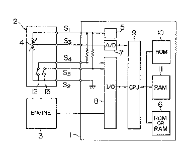
Fig. 1 is a diagram showing a configuration of an
embodiment of the present invention.
Fig. 2 shows a configuration of a conventional
control system.
Fig. 3 shows an actual appearance of the prior art.
Fig. 4 is a diagram showing a compensation value of
a target idle engine speed.
Fig. 5 is a flowchart showing the operation of an
embodiment of the present invention.
DESCRIPTION OF THE PREFERRED EMBODIMENTS
An embodiment of the present invention will be
- 2a -

1308460
1 described below. Fig. 2 is a diagram showing a conven-
tional system of idle engine speed control, in which
the opening of an air path 16 bypassing a throttle valve
15 is controlled by a proportional solenoid valve 14
driven by a duty factor signal. In this case, the idle
engine speed is set to a preprogrammed target value,
such as 700 rpm, by feedback control through a control
unit 1 of an engine 3. The method of this control, which
will not be described in detail herein, is well known.
This target value is set aimed at a central value
considered optimum beforehand. Nevertheless, it may be
desired to make some fine adjustment depending on engine
quality variations or secular variations.
For this purpose, according to the prior art,
a fine adjustment mechanism 4 such as shown in Fig. 2
is added to the control unit 1. The fine adjustment
mechanism 4 is a potentiometer of rotary type, and is
adapted to be rotated by a screw driver from the side
of a case of the control system 1 in the manner shown
in ~ig. 3. The control unit 1 reads the neutral voltage
VR of the potentiometer 4 through an A/D converter 7,
and according to the value thus read, searches a table
having characteristics shown in Fig. 4 to determine a
compensation value aNSET of the target engine speed.
This compensation value is added to a central value
NSET~ of target engine speed set in advance thereby,
thus calculating the final target engine speed NSET.
Specifically,

~3~184~;0
SET NSET~ ~NSET
where ~NSET - f (V )
1 Then, in a manner to attain the target engine speed
NSET, the feedback control is effected. The control
unit 1 includes a CPU 9 for cGmputation operation, a
memory (ROM 10, RAM 11) for storing a program and control
constants, and an I/O circuit 8 for input and output
control as well known.
In this system which has the fine adjustment
mechanism 4 easy to operate as mentioned above, the
tamper-proofness is adversely affected. Also, the fact
that the control system 1 has a movable adjustment
mechanism results in the disadvantage that the setting
is liable to deviate under vibrations or the system is
subject to damage by faulty operation. According to
the present invention, these disadvantages are obviated
by a configuration shown in Fig. 1.
The potentiometer 4 shown in Fig. 2 is mounted
on an adjustment unit 2 separate from the control system 1.
The adjustment unit 2 also has a circuit 12 for producing
a mode switch signal and a circuit 13 for producing a
compensation amount memory command signal. According to
the embodiment under consideration, these circuits are
all realized by an on/off switch. The adjustment unit
2 is adapted for electrical connection to the control
unit 1 through a connector. In the embodiment under
consideration, such a connection is established by five

P3~60
1 signal wires including a power wire Sl for the potentio-
meter 4, an earth wire S2, a neutral voltage signal wire
(compensation signal wire) S3 for the potentiometer 4,
a mode switch signal wire S4 and a compensation amount
command signal wire S5. Now, the signal of the wires Sl,
S2, S3, S4 and S5 are designated as Sl', S2', S3', S4'
and S5' respectively hereafter.
On the control unit 1 side, the power wire Sl
is supplied with a constant voltage of +5V from a constant
voltage source 5, the wire S2 is connected to the earth
of the control unit 1, the wire S3 is connected to the
A/D converter 7, and the wires S4 and S5 are pulled up
to the power of +5V of the constant-voltage source through
a resistor on one hand and are connected to the I/O 8 on
the other hand. As a result, voltage levels of the wires
S4 and S5 are read as "low" (hereinafter referred to as
"L") when switches 12, 13 are on and as "high" (herein-
after referred to as "H") when the switches 12, 13 are off.
The S4' is read as "H" when the adjustment unit
2 is not connected to the control unit 1 or when the
switches 12, 13 are off even if the adjustment unit 2 is
connected to the unit 1. In this case the control unit 1
operates in normal mode and the input signals of the
wires S3 and S5 have no meaning (and ignored).
When the adjustment unit 2 is connected to the
control unit 1 and the ~witch 12 is turned on with the
S4' being read as "L", on the other hand, the control unit
1 shifts to the adjustment mode, thereby making the signals

~3~)8460
1 of the wires S3 and S5 valid. In the adjustment mode, the
signal S3 is read through the A/D converter, and then the
following calculation is made in a manner similar to the
prior art:
SET SET~ ~NSET
In the process, the switch 13 is off (that is, S5' - "H"),
and as long as the S5' is "H", the value ~NSET is updated
successively with the change in the S3' signal and the
resulting value is stored temporarily in RAM 11. The engine
speed is monitored by operating the potentiometer 4,
and when the desired engine speed is reached, the switch
13 is turned on to reduce the signal S5' to "L". Then,
the control unit 1 writes the value ~NSET stored in the
RAM 11 into a non-volatile memory 6 such as EEPROM or
RAM backed up with a battery. In this embodiment, the
circuit is configured in ~uch a way that when the S5' is
"L" the wire S3 becomes invalid, and therefore if the
value of ~NSET written in the memory 6 is to be rewritten,
the condition of S5' - "H" is required to be restored
(with the switch 13 off) to repeat the aforementioned
process. Once the desired value of ~NSET is written
in the memory 6 in this way, the switch 12 is turned
off and further the adjustment unit 2 is disconnected
from the connector, thus cutting the connection between
the control unit 1 and the adjustment unit 2, whereby
the signal S4' is made "H" for operation in normal mode.
In normal mode, the control unit 1 reads out the value of
~NSET written in the memory 6, and by use of this value,

~3~)~3460
1 computes the value NSET = NSET~ SET'
is effected with the resulting NSET as a target engine
speed. A flowchart of the aforementioned operation is
shown in Fig. 5.
Step 20 decides whether the mode switch signal
S4' is "H" or "L", and if it is "L", the adjustment mode
is decided. The next step 21 decides whether the
compensation amount memory command signal S5' is "H" or
"L", and if it is "H", the compensation value ~NSET is
changed. Step 22 reads the neutral voltage VR of the
potentiometer 4, followed by step 24 where a binary
data of ~NSET proportional to the neutral voltage is
stored in the RAM 11. The next step 25 adds the target
engine speed central value NSET~ and the compensation
value NSET so that the final target engine speed NSET
is determined to decide whether the desired target
engine speed has been reached or not. If the desired
engine speed is not yet reached, the neutral point
potential is changed by the potentiometer 4, followed
by repeating the operation of the steps 22, 24 and 25.
When the desired engine speed reaches, by
contrast, in step 21 the switch 13 is turned on and
reduces the signal S5' to "L", followed by step 23 where
the value ~NSET is shifted from the RAM 11 to the memory
6 made of a RAM or an EEPROM backed up.
In the case where the S4' is "H" at step 20, a
normal control mode prevails, and step 26 determines
the final tar4et engine speed NSET from the value ~NSET

~3t~8460
1 stored in the memory 6 and the value NSET~ stored in
the ROM 10.
An embodiment of the present invention was
explained above as an adjustment of a target value of
idle engine speed. It is evident, however, that a
similar configuration is applicable also to various
controls such as compensation of the air-fuel ratio.
Unlike in the embodiment described above, a
control output (such as a duty factor of the an ISC
valve drive signal), but not a control target value,
may be adjusted, in which case the feedback control is
suspended but the output is fixed to a predetermined
value in adjustment mode.
Further, instead of using an independent digital
or analog signal as S3', S4' or S5' as in the present
embodiment, a common signal wire may be used by serial
communication.
Furthermore, in normal control mode, it is also
possible to correct the value written in the memory 6 in
adjustment mode sequentially for compensation of secular
variations, etc. by what is called the learned program-
ming.
According to the present invention, the
adjustment is impossible without an exclusive adjustment
unit, and therefore the tamper-proofness is not adversely
affected, while at the same time improving the reliability
with movable parts eliminated.

Dessin représentatif
Une figure unique qui représente un dessin illustrant l'invention.
États administratifs

2024-08-01 : Dans le cadre de la transition vers les Brevets de nouvelle génération (BNG), la base de données sur les brevets canadiens (BDBC) contient désormais un Historique d'événement plus détaillé, qui reproduit le Journal des événements de notre nouvelle solution interne.

Veuillez noter que les événements débutant par « Inactive : » se réfèrent à des événements qui ne sont plus utilisés dans notre nouvelle solution interne.

Pour une meilleure compréhension de l'état de la demande ou brevet qui figure sur cette page, la rubrique Mise en garde , et les descriptions de Brevet , Historique d'événement , Taxes périodiques et Historique des paiements devraient être consultées.

Historique d'événement

Description Date
Inactive : CIB de MCD 2006-03-11
Inactive : Demande ad hoc documentée 1995-10-06
Le délai pour l'annulation est expiré 1995-04-06
Lettre envoyée 1994-10-06
Accordé par délivrance 1992-10-06

Historique d'abandonnement

Il n'y a pas d'historique d'abandonnement

Titulaires au dossier

Les titulaires actuels et antérieures au dossier sont affichés en ordre alphabétique.

Titulaires actuels au dossier
HITACHI, LTD.
Titulaires antérieures au dossier
MASAAKI FUJISAWA
Les propriétaires antérieurs qui ne figurent pas dans la liste des « Propriétaires au dossier » apparaîtront dans d'autres documents au dossier.
Documents

Pour visionner les fichiers sélectionnés, entrer le code reCAPTCHA :


Pour visualiser une image, cliquer sur un lien dans la colonne description du document (Temporairement non-disponible). Pour télécharger l'image (les images), cliquer l'une ou plusieurs cases à cocher dans la première colonne et ensuite cliquer sur le bouton "Télécharger sélection en format PDF (archive Zip)" ou le bouton "Télécharger sélection (en un fichier PDF fusionné)".

Liste des documents de brevet publiés et non publiés sur la BDBC .

Si vous avez des difficultés à accéder au contenu, veuillez communiquer avec le Centre de services à la clientèle au 1-866-997-1936, ou envoyer un courriel au Centre de service à la clientèle de l'OPIC.

({010=Tous les documents, 020=Au moment du dépôt, 030=Au moment de la mise à la disponibilité du public, 040=À la délivrance, 050=Examen, 060=Correspondance reçue, 070=Divers, 080=Correspondance envoyée, 090=Paiement})


Description du
Document 
Date
(aaaa-mm-jj) 
Nombre de pages   Taille de l'image (Ko) 
Revendications 1993-11-03 7 206
Abrégé 1993-11-03 1 9
Dessins 1993-11-03 2 36
Description 1993-11-03 9 282
Dessin représentatif 2002-02-10 1 10