Sélection de la langue

Search

Sommaire du brevet 1315957 

Énoncé de désistement de responsabilité concernant l'information provenant de tiers

Une partie des informations de ce site Web a été fournie par des sources externes. Le gouvernement du Canada n'assume aucune responsabilité concernant la précision, l'actualité ou la fiabilité des informations fournies par les sources externes. Les utilisateurs qui désirent employer cette information devraient consulter directement la source des informations. Le contenu fourni par les sources externes n'est pas assujetti aux exigences sur les langues officielles, la protection des renseignements personnels et l'accessibilité.

Disponibilité de l'Abrégé et des Revendications

L'apparition de différences dans le texte et l'image des Revendications et de l'Abrégé dépend du moment auquel le document est publié. Les textes des Revendications et de l'Abrégé sont affichés :

  • lorsque la demande peut être examinée par le public;
  • lorsque le brevet est émis (délivrance).
(12) Brevet: (11) CA 1315957
(21) Numéro de la demande: 1315957
(54) Titre français: ETRIER A RESSORT AUTO-CENTREUR
(54) Titre anglais: SELF-ALIGNING SPRING CLAMP
Statut: Périmé et au-delà du délai pour l’annulation
Données bibliographiques
(51) Classification internationale des brevets (CIB):
  • F16L 33/02 (2006.01)
  • F16L 33/025 (2006.01)
(72) Inventeurs :
  • SPAULDING, GEORGE E. (Etats-Unis d'Amérique)
(73) Titulaires :
(71) Demandeurs :
(74) Agent: MACRAE & CO.
(74) Co-agent:
(45) Délivré: 1993-04-13
(22) Date de dépôt: 1989-02-09
Licence disponible: S.O.
Cédé au domaine public: S.O.
(25) Langue des documents déposés: Anglais

Traité de coopération en matière de brevets (PCT): Non

(30) Données de priorité de la demande:
Numéro de la demande Pays / territoire Date
176,208 (Etats-Unis d'Amérique) 1988-03-31

Abrégés

Abrégé anglais


ABSTRACT
A circular spring clamp comprises a spring
steel band having a reentrantly folded latch hook at
one end and a radially outwardly extending latch at the
opposite end with a concave latching surface thereon.
The band has radially outwardly extending flanges on
opposite edges thereof for guidance and retention of
the latch hook.

Revendications

Note : Les revendications sont présentées dans la langue officielle dans laquelle elles ont été soumises.


THE EMBODIMENTS OF THE INVENTION IN WHICH AN EXCLUSIVE PROPERTY
OR PRIVILEGE IS CLAIMED ARE DEFINED AS FOLLOWS:
1. A circular spring clamp comprising:
a spring steel band having a latch hook at one end and a
latch at the other end,
said latch hook comprising a radially outwardly extending
portion, a circumferentially extending portion, and a radially in-
wardly reentrantly folded portion having a terminal edge engageable
with said latch,
said latch having a concave latching surface thereon for
the acceptance of the terminal edge of said latch hook,
a pair of radially outwardly extending flanges on opposite
edges of the latching surface of said latch, the reentrantly folded
portion of said latch hook being substantially equal to the spacing
between said flanges so as to be acceptable therebetween for positively
positioning said latch hook.

Description

Note : Les descriptions sont présentées dans la langue officielle dans laquelle elles ont été soumises.

13~5~Y~
SELF-ALIGNING SPRING CLAMP
BACKGROUND OF THE INVENTION
Spring clamps that are openable to effect
a~embly about a hose are well taught in the prior art.
For example, the~patents to Bright 3,295,176; Thomas
3,266,109; lchikawa 3,370,122j Edwards 3,435,823;
Philbrook 1,~74,550; Parr 1,379,476 and Robertshaw
210,560 teach an openable spring clamp having locking
mea~ to effect closure of the clamp. However, each of
the clamps taught in the aforesaid patent~ exhibit one
or more de~iciencies which, in field use, limits uti-
lity of the clamp. Specifically, while the clamps
taught in the aforesaid patents utiliæe a mechanical
interlock in one form or another, exper~ence has indi-
cated that a guidance and retention system for the
latch is highly desirable to ensure proper alignment
and posltive retention.
SUMMARY 0~ THE INVENTION
A clamp in accordanee wi~h a constructed
embodiment of the instant invention comprises a flat
band o~ steel having locking means at opposite ends
thereof to effeot closure of the clamp about a tube.
The locking means ¢omprises a hook at one end of the
band that effeots a mechanical interlock with a latch
at the other end of the clamp. Ramp-type flanges on
the band guide the hook into engagement with the latch
,

1315~ ~
and retain the hook in engagement therewith by precluding lateral
movement of the hook relative to the latch.
Generally speaking, therefore, the present invention provides
a circular spring clamp comprising: a spring steel band having a
latch hook at one end and a latch at the other end, the latch hook
comprising a radially outwardly extending portion, a circumferentially
extending portion, and a radially inwardly reentrantly folded portion
having a terminal edge engageable with the latch, the latch having a
concave latching surface thereon for the acceptance of the terminal
edge of the latch hook, a pair of radially outwardly extending flanges
on opposite edges of the latching surface of the latch, the reentrantly
folded portion of the latch hook being substantially equal to the
spacing between the flanges so as to be acceptable therebetween for
positively positioning the latch hook.
BREIEF DESCRIPTION OF THE DRAWINGS
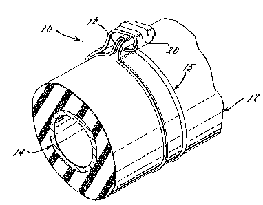
Figure 1 is a perspective view of a clamp in accordance
wlth a constructed embodiment of the instant invention;
Figure 2 is a fragmentary view of the clamp of Fig. 1 in
the open condition;
Figure 3 is a view showing the clamp in the fully closed
condition; and
Figure 4 is a view taken along the line 4-4 of Fig. 3.
DETAILED DESCRIPTIO~ OF THE PREFERRED
~ EMBODIMENT OF THE INVENTION
As seen in Fig. 1 of the drawings, a spring clamp 10, in
accordance with a preferred constructed embodiment of the instant in-
vention, i~5 disposed about a hose 12 for the retention thereof about
a tube 14. The clamp 10 comprises a band 15 having a latch 18 at
one end and a latch hook 20 on an opposite end. The latch hook 20
engages a radially outwardly extending concave latching surface 21
, ' ' . .
sp:~J~

~ ` 131aY~'^i
on the latch 18 in biting and mechanical locking engagement. The
latch hook 20 has a radially outwardly and circumferentially extending
portion 23 having a centrally disposed reinforcing rib 24 that term-
inates at the junction of the hook 20 with the band portion 15 of
the clamp 10.
2a
. ~ 8p: ~t

~31~7
As een in Fig. 3 of the drawing, a
reentrantly folded end portion 26 of the latch hook 20
is preferably provided with a chisel edge to effect
biting engagement with the latch 18 as the hook 20
moves radlally inwardly along the surface 21 thereof.
Thus, the hook 20 effects biting engagement a3 well as
a mechanical lock with the latch 18. The ultimate
mechanical and biting relationship between the lat¢h
hook 20 and latch 18 is best illustrated in Fig. 3 of
the drawing.
In accordance with the instant invention, and
as best seen in Fig. 4, the end portion 26 of the hook
20 is reduced in width so as to be accommodated between
radlally outwardIy directed ~langes 40 and 42 on oppo-
sLte edges of the band 15. Initially, as seen in Fig.
2, the flanges 40 and 42 guide the end portion 26 of
the latch hook 20 upon advanoement thereof toward the
latoh 18. After the hook 20 rides over the latch 18
and engages the ooncave surface 21 thereof, the flang,es
40 and 42 restrain the end portion 26 of the hook 20
from movement laterally o~ the band 15.
~ The clamp 10 may~ be provided with a
tensioning loop 30 which', since Oand lsngth is
nonadj~ustable, functions to mainta~n tension on the
clamp 10 within a given toIerance range.
ssembly of the clamp 10 about the hose 12
i9 initiated by drawing the latch hook 20 toward the
latch 18 by a suitable pliers-type tool 50. The end
portion Z6 of the hook 20 is guided by the flanges 40
and 42 on the band 15 during this phase of assembly.

~ 3 ~
A~ the latch hook 20 reache~ the latch 18 it ride~
thereover until the biting edge thereon engage~ the
concave surface 21 oP the latch 18 in biting engage-
ment. The hook 20 i~ thereafter bia~ed radially
inwardly to the fully closed po~ition shown in Fig. 4,
the flanges 40 and 42 precluding lateral movement
thereof.
From the foregoing de~cription it ~hould be
apparent that the spring clamp of the in~tant invention
provide~ for positive retention of the latch hook on
the latch which precludes ~purious opening of the
clamp.
While the preferred embodiment of the inven-
tion ha~ been disclosed, it should be appreciated that
the invention i~ ~u~ceptible of modification without
departing from the ~cope of the following claim~.

Dessin représentatif
Une figure unique qui représente un dessin illustrant l'invention.
États administratifs

2024-08-01 : Dans le cadre de la transition vers les Brevets de nouvelle génération (BNG), la base de données sur les brevets canadiens (BDBC) contient désormais un Historique d'événement plus détaillé, qui reproduit le Journal des événements de notre nouvelle solution interne.

Veuillez noter que les événements débutant par « Inactive : » se réfèrent à des événements qui ne sont plus utilisés dans notre nouvelle solution interne.

Pour une meilleure compréhension de l'état de la demande ou brevet qui figure sur cette page, la rubrique Mise en garde , et les descriptions de Brevet , Historique d'événement , Taxes périodiques et Historique des paiements devraient être consultées.

Historique d'événement

Description Date
Inactive : CIB de MCD 2006-03-11
Inactive : Demande ad hoc documentée 1996-04-13
Le délai pour l'annulation est expiré 1995-10-15
Lettre envoyée 1995-04-13
Accordé par délivrance 1993-04-13

Historique d'abandonnement

Il n'y a pas d'historique d'abandonnement

Titulaires au dossier

Les titulaires actuels et antérieures au dossier sont affichés en ordre alphabétique.

Titulaires actuels au dossier
S.O.
Titulaires antérieures au dossier
GEORGE E. SPAULDING
Les propriétaires antérieurs qui ne figurent pas dans la liste des « Propriétaires au dossier » apparaîtront dans d'autres documents au dossier.
Documents

Pour visionner les fichiers sélectionnés, entrer le code reCAPTCHA :


Pour visualiser une image, cliquer sur un lien dans la colonne description du document (Temporairement non-disponible). Pour télécharger l'image (les images), cliquer l'une ou plusieurs cases à cocher dans la première colonne et ensuite cliquer sur le bouton "Télécharger sélection en format PDF (archive Zip)" ou le bouton "Télécharger sélection (en un fichier PDF fusionné)".

Liste des documents de brevet publiés et non publiés sur la BDBC .

Si vous avez des difficultés à accéder au contenu, veuillez communiquer avec le Centre de services à la clientèle au 1-866-997-1936, ou envoyer un courriel au Centre de service à la clientèle de l'OPIC.

({010=Tous les documents, 020=Au moment du dépôt, 030=Au moment de la mise à la disponibilité du public, 040=À la délivrance, 050=Examen, 060=Correspondance reçue, 070=Divers, 080=Correspondance envoyée, 090=Paiement})


Description du
Document 
Date
(aaaa-mm-jj) 
Nombre de pages   Taille de l'image (Ko) 
Abrégé 1993-11-09 1 11
Revendications 1993-11-09 1 19
Dessins 1993-11-09 1 40
Description 1993-11-09 5 139
Dessin représentatif 2001-07-31 1 14
Correspondance 1993-01-18 1 28