Note : Les descriptions sont présentées dans la langue officielle dans laquelle elles ont été soumises.
3 ~ 3
--1--
D~SCRIPTIG~
DEVICE FOR REDUCING FIBROUS PRODUCTS
:
I The present invention relates to devices for
reducing fibrous products. In paxticular, but not
exclusively, ~he inven~ion relates to macerators for
, reducing soiled paper pulp pedpans, urine bottles and
the like, ~o enable them ~o be discharged into a sewer.
One form of existing device, used mainly, but not
exclusively, as a macerator, is ln the form of a
generally cylindrical, upright drum having a rotatable
cutting blade disposed at the centre of its base, the
blade being rotatable by means of an electric motor.
An annular arrangement of teeth is disposed in the
macerator, just below the level of the blade so that
material which is first chopped roughly by the blade is
subsequently ground into much smaller particles between
~he moving blade and ~he stationary cutting teeth. In
use, an article to be macerated is placed in the
container, and a lid closes off the aperture. During
the operating cycle, water is fed continuously into the
container and the motor is continuously operated.
Particles are discharged from the container when they
have been ground sufficiently to be able to pass
through the gap between the moving blade and the
stationary ~eeth.
Such a device has tha disadvantages that the motor
runs continuously throughout the cycle, and also that
;s 1~3183~3
it may be possible far rela~ively large, elongate
particles o material to pass through ~he said gap
I lengthways, and subsequen~ly coalesce with other
¦ particles, thus causing a blockage in a drain to which
the device is connected.
I Another form of device is in the form of an.
¦ elongate bath, generally U-shaped in cross-section,
which has a ro~atable shaft passing along the elongate
axis of the bath~ the shaft being provided with a
plurali~y of knife blades. A housing is positioned
beneath the said bath, and communicates therewi~h by
means of a plurali~y of 3/4" (1.9c~ apertures. The
housing is connected to a drain via a ball valve.
In use, an article to be macerated is placed in the
lS bath, and a lid closes off its aperture. A fixed
quantity of water is fed into the container, and the
shaft is rota~ed, whereby the knife blades perform a
chopping action on the contents. ~en the particles
are smaller than 3/4" ~1~9cm) they are able to pass
through the said apertures, and are then discharged
when the ball valve ls opened.
However, it is possible for particles larger than
3/4" (1.9cm) to be discharged, if, or example, they
~ pass lengthways through the apertures. Thus, the;~ 25 possibility of drain blockage is s~ill present.
.
~ ~3L8~;3
-3-
With ~he prior art devices, large particles can
lead to blockages within the drainage system to whlch
~ the devices are connected, and ln the l~tter system
J such particles can also restrict c:orrect operetlon of
the outlet valve.
It is an object of the inventi.on to provide ~
reducing device which reduces articles to the necessary
size efficiently.
In accordance with a first aspect of the present
inven~ion, a device for reducing fibrous products
comprises a housing for receiving the products to be
reduced and agitating means rotatably mounted within
the housing for reducing the products, the agitating
means being located and/or orientated assymetrically
within the housing,
In one embodiment, the housing comprises a
generally cylindrical housing, and the axis of rotation
of the agitating means is inclined to the longi~udinal
axis of the cylindrical housing. The axes of rotation
of the housing and of the agitating means ~ay or may
not ~ntersect.
Alternatively, or in addition, the agitating means
is displaced or offset from the longitudinal axis of
the cylindrical housing. I~is results in a high
hydraulic shear between the agitating means and the
wall of the housing. In one embodiment, the ~gitating
means is in the form of a rotatable blade which is
closely spaced from the wall of the housing.
~3~83~3
.
--4--
Preferably, the device is arranged with the
longitudinal axis of the cylindrical housing dlsposed
vertically. The upper end of the housing may be
provided with a closable lido The lid may be provided
with a water spray for spraying water into the housing,
and is preferably provided wlth an outlet valve for
discharging reduced articles.
It is a further object of the present invention to
provide an improved valve~ and in particular, but not
exclusively, a valve which is suitable for use with a
device for reducing fibrous products.
In accordance with a second aspect of the present
inventlon, there is provided a valve comprising a valve
housing, a valve seat, a valve closure member within
the housing comprising a relatively rigid sealing
portion adapted ~o engage sealingly with the valve seat
and a flexible diaphragm portion disposed around the
periphery of the sealing portion, the diaphragm portion
sealingly abutting a portion of the valve housing to
define a pressure chamber between the valve closure
member and the valve housing, and ~ part for applying
fluid pressure to the chamber in order to urge the
sealing portion into engagement with the valve seat.
Such a valve produces a positive sealing action,
and is particularly useful as an exit valve for a
device as hereinbefore described. Macerators are
~ 3~3~3
--5--
usually supplied with pressurised water whlch is
sprayed into the device and which now may also be used
; ~o ac~uate ~he valve.
I Also, the water used to actuate ~he valve is
subsequently discharged in~o the device durlng later
operation.
Also, the valve as described above has excellent
characteristics. Firstly, if a non-reducable item is
accidentally placed in the device and lodges between
the valve closure member and the valve seat, then
although the valve closure member is s~ill urged
towards a closed position, it is not dangerous, since a
set water pressure is applied to the valve closure
member. In contrast, with a solenoid operated valve an
overload might occur as the solenoid tried to close the
valve closure member. Also, the valve is self-
aligning, with ~he result that closure of the valve
closure member is still permitted in many circumstances
if particles are trapped between it and ~he valve
seat. The valve closure member can form around the
particles deposited.
Preferably, therefore, the valve ls actuated by
means of pressurised fluid, e.g. water, which is fed to
the device to which the valve is connected.
Preferably, the valve further comprises biassing
means to bias the valve closure member against the
force of applied fluid. The biassing means may
` 13~L~3~3
--6--
comprise resiliently deformable means, such as a
spring. In one embodiment, the spring is a tension
spring.
The valve seat preferably defines an exit aperture.
The invention also includes a device for reducing
¦ fibrous artlcles when fitted with a valve in accordance
with the present invention, and in particular it
includes a macerator when fitted with a valve in
accordance with the present invention.
By way of example only, a specific embodiment of
the present invention will now be described, with
reference to the accompanying drawings, in which:-
Fig.l is a side view of an embodiment of reducing
device in accordance with the present invention;
Fig.2 is a schematic cross-section of the device of
Fig.l, also showing the connections between the various
components;
Figs. 3 and 4 are perspective and plan views
respectively of a por~ion of the device of Fig.l,
showing the positioning and orientation of certain
components of the dPvice;
Fig.5 is a detail cross-section of an embodiment of
valve in accordance with ~he present invention, used on
the device of Fig.l;
Fig. 6 is a side view of a lid lock arrangement of
the device of Fig. l; and
` ~3~3~3
--7--
Fig.7 ~s an illustration showing the operation of
the device of Fig.l.
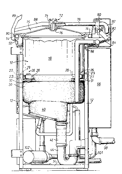
Referring to Figs. 1 ~o 4, the device comprises a
I stainless steel drum 10 supp~orted on a framework hav~ng
four vertical legs 12 (only two of which are visible in
. Fig.l) arranged in square formation and eight cross-
members 14 interconnecting the upper ends and the lower
ends of the legs 12. The upper end of the drum is
open, and is provided with a closable lid 16.
me drum is in the form of upper and lower portions
18,20, each being generally cylindrical internally.
The lower edge of the upper portion 18 is received on a
peripheral rim 22 on the upper edge of the lower
portion 20, the two portions being sealed by an annular
seal 24 between the upper portion 18 and the rim 22.
The upper and lower portions are releasably secured
together by means of a seal locating ring 25 which sits
: on top of the seal 24 and is held in position by a
plurality of plates 27 which are releasably connectible
to the lower portion 20 by means of bolts 29 passing
through the plates 27 and a lug 28 of the lower
portion, thereby compressing th~ seal 25. The drum is
mounted on the frame by means of lugs 31 attached to
: the llpright legs 12 and by bolt and nut combinations 26
passing through the lugs and the lug 28.
~l3~83~3
. -8-
The lower end of the lower drum portion 20 is
closed off by 2 base having a gently downw~rdly
sloping, generally frusto~conical portion 30 whose
plane is normal to the longitudinal axis of the drum,
the planar portion being contiguous with an inclined
! plansr portion 32, inclined at an angle of 30~ to the
¦ horizontal. The portion 30 is also provided wi~h a
circular exit aperture 36 at its base. The circular
aperture may be closed off by means of a diaphragm
valve 38 in ~ valve housing 40 beneath the apertur~,
and when the valve is open the aperture 36 communicates
with a further aperture 42 in the base of the valve
housing. The valve housing 40 is connected via the
aperture 42 to an outlet pipe 44, the first part 46 of
which is transparent to enable the flow of pulp to be
seen. The pipe 44 is formed into a U-bend downstream
from the transparent portion.
The inclined planar portion 32 is provided with a
rotatably mounted blade 48 which is rotatable by means
of an electric motor 50 whose output shaft 51 passes
sealingly through ~n aperture in the portion 32. As
best seen in Fig.2, the blade 48 is not symme~rical,
bu~ comprises two port~ons, one on either side of the
rotational axis, one inclined upwardly and the other
inclined downwardly. The axis of rotation of the motor
and of the blade is normal to the plane of the inclined
!
` ~31~3~3
g
portion 32, i.e. is inclined to the longitudin~l axis
of the drum 10. Moreover, the blade 48 and its
i rotational axis are offset laterally from the
I longi~dinal axis of the drum. It should also be noted
s that the longitudinal axis of the drum, the rotational
axis of the motor and the centre of the circular
aperture 36 are no~ aligned, and that the rotational
axis of the blade 48 does not intersect th~
longitudinal axis of the drum.
It is also noted that the closest separation of the
blade and the interior of the drum is about 1/2"
(1.27cm), which has an important effect on the articles
to be reduced, since the small separation causes a
lar~e hydraulic shear on par~icles passing
therethrough. It is also important that after the
closest separation of the blade and the drum, the sense
of rotation of the blade ls such that the material
flows down the sloping portion 32 as opposed to up the
sloping portion. This is achieved by rotating the
blade anti-clockwise as seen in Fig. 4, and produces a
more effective reducing action, although the device
will still work, albeit less effectively, with
clockwise rotation of the blade.
The diaphragm valve 38 is illustrated in more
detail in Fig.5 The valve omprises a valve housing
40, formed integrally with the lower drum portion 20
and a ~alve closure member 52. The valve closure
member is moulded from a single piece of polyurethane
'
~ 3~ 8~3
-10-
and comprises a flexible, perip~eral, dished, stepped
diaphragm portion 54 and a central, plug portion 56.
The peripheral edge of the plug portion 56 is chsmfered
to provide a shoulder which can engage sealingly wi~h a
~ valve seat formed by the material defining the aperture
36. The valve housing also comprises a rigid metal
! cover plate 58, which is positioned sealingly over the
undersurface of the in~egrally formed portion of the
valve closure member by means of securing bolts 60
which pass through the cover plate 58 and the periphery
of the dlaphragm and are received in threaded bores in
the integrally formed portion of the valve houslng.
A metal tube 62 passes through, and is secured to,
the diaphragm cover plate 58. Ports 63 are provided in
the tube, within the housing cover plate 58. One end
of a tension spring 64 is secured to the lower end of
the tube by means of a collar 66 secured therein. The
o~her end of the spring is secured to the shaft of a
bolt 68 whose head is embedded in the plug portion 56
of the valve closure member. The tension spring
biasses the plug portion 56 out of engagement with the
valve sea~, but the movemen~ of the diaphragm is
limited by the upper end of the tube 62 which abuts the
undersurface of the plug portion after the plug portion
has moved a short distance out of engagement with the
valve seat to open ~he valve. The opposite end of the
1~3~83~3
.
tube 62 Ls connected ~o a water supply pipe 70 in order
tha~ the ~alve may be closed by means of water pressurP
acting on the undersurface of the valve closure member,
~s will be explained herein~fter. An air relief tubP
¦ 5 71 which allows the valve to open, as will be
explained, also passes sealingly through the housing
cover plate 58.
The upper end of ~he drum 10 is closable by means
of a ~ircular domed lid 16. The lid is provided with a
spray head 72 in its centre, which comprises a housing
74 and a poppet 76 which is screw-threadedly received
in the housing 74. A gap is left between the head of
the poppet and the housing, and water entering the
housing through a supply pipe 78 is expelled through
the gap in the form of a continuous cylindrical
cur~ain. The supply pipe is secured to the spray head
housing 74 and is used to pi~otally mount the lid 16.
~he end of the pipe 78 remote from the spray head is
provided with a lug 80 which is used to mount the pipe
78 on A pivot 81. A bar 82 is mounted on the pivot 81;
at one end and is movable with the pipe 78 ~nd lid 16.
The other end of the bar 8~ is att~ched to one end of a
tension spring 84, the other end of which is connected
to a further mounting lug 86 which is secured to a
frame member 12. The spring urg~s the lid towards its
opened position. The pipe 78 is supplied with water by
means of a hose 87.
3 ~ 3
-12-
A metal bar 88 extends from the spray head 72 on
~he opposi~e side from the pipe 78, and ~he end of the
bar ~8 remote from ~he spray head is provided wi~h an
opening handle 89 which is pivotable about a pivot 90,
by means of which the handle c~n be hooked under ~
corresponding recess member 92 attached to the ~rame,
into a securing position in which the periphery of the
lid is held sealingly against an annul~r seal 94
extending around the upper peripheral edge of the drum
16.
The lid is also provided with a lid lock,
illustra~ed in Fig. 6, which is a view of the lid hinge
region Erom the opposite side of the device than shown
in Fig. 1. The lock comprises a solenoid S having a
plunger 91 which is engageable in a recess in a spring
loaded pawl 93 which is pivotally mounted to the frame
of the device and gravity-biassed in the clockwise
direction as shown in Fig. 6. The pawl is engageable
with a finger 95 which is rigidly connected to the lid
20 I and which pivots with it about pivot 81. The solenoid
S is shown in Fig. 6 in its actuated state in which the
plunger 91 is withdrawn, permitting the pawl 93 to
engage with the finger 95, and prevent~ng the lid from
opening. Upon de-engergisation of the solenoid S, the
plunger projects downwardly as shown in Fig. 6 and
causes the pawl 93 to move against its spring bias out
of engagement with the finger 95, allowing the lid to
be opened.
~3~83~3
-13-
A water cistern 96 is provided ~t the rear of the
device, mounted on the frame. The cistern has a
c~pacity of thirty-two lltres and ls fed from a
conventional flo~t valve inlet 100. An overflow pipe
98 iS also provided. The cistern feeds water via a
tube 101 to a Stuart Turner 12 Mk~ 3 electri~ water pump
i 102 Yi8 a stop valve 104. The pump 102 feeds water via
a 22mm diameter clear plastics hose 106 to the hose 87
and then to the pipe 78 and the spray head 72.
1~ A further tube 108 branches from the tube 106 snd
is connected via a restrictor 110 and a non-return
valve 112 to the tube 62 extending out of the valve
housing 40. The air relief tube 71 also extends out of
the valve cover plate 58 and is connected to he
opposite side of the valve closure diaphragm 52 by
means of a tube 116 via a solenoid valve 118, ~he tube
116 co-operating with a passage 120 in the valve
housing. A further tube 122 branches from the tube
116, and is connected to the drum near its upper edge,
and also to a non-return valve 124.
A further tube 126 branches from the tube 106, and
supplies water to the region of the seal of the motor
against the drum. The seal between the motor and the
drum is a conventional ceramic seal, and as with
conven~ional ceramic seals, a flow of pressurised water
is provided to prevent debris from fouling the seal.
~3~3~3
-14-
By keepilg the pressure of the water fed to the seal
higher than that in the drum, any flow which occur~
! will be uutward from the seal into the drum. An outlet
¦ tube 128 from the motor 50 is provided, and
communicates with ~he valve housing 40, thereby
; disposing of any fluid which manages to seep past the
seal.
The device is under the control of a control unit,
illustrated sche~atically by 130, and operated by a
push button 132. The control unit comprises a
plurality of cam-operated switches which act to actuate
different functions of the device in a pre-set
sequence, as will be explained. Each function i9
: controlled by a respective cam mounted on a common axle
which rotates once per disposal cycle.
In use~ an article to be reduced is placed inside
the drum and the lid is closed. Due ~o the inclined
portion 32 of the b~se, the article does not lie flat
on the base, but usually assumes an inclined
orientation permitting the blade to con~ac~ the article
at more than one location~ The push button is
depressed, and immedi~tely the lid lock solenoid is
actuated by the control unit, thus preventing access ~o
the interaor of the drum until the end of the cycle.
One and a half seconds later, the con~rol unit Actuates
~he pump 102, ~nd the pressure of water opens the
``` 13~83~
-15-
non-re~urn valve 112. The control unit also closes the
solenold valve 118. In ~his way, water is fed to the
I chamber defined by the valve closure member 52, the
¦ integrally formed valve housing 40 and the valve
closure plate 58, thereby urging the sealing portion 56
I of the valve closure member 52 into sealing abu~ment
i wi~h the valve seat against the force of the valve
spring 64. Water is also fed into the drum 10 through
the valve spray head 72.
The pump is actuated for a period of thlrteen and a
half seconds, which permits twelve litres of water to
be pumped into the drum. As the pump is stopped by the
control unit, the non-return valve 112 shuts, which
severs the connection between the pump 102 and the
valve 38. The shut non-return valve 112 thus ensures
that the water pressure in the valve 38 is maintained
when the pu~p is turned off, thereby keeping the valve
38 closed.
One second before the pump is stopped, the control
unit actuates the cutter motor 50, thereby causing the
blades 48 ~o rotate rapidly and reduce ~he contents of
the devlce to a slurry with the water fed in by the
pump. Since the cutter blade is arranged
assymetrically in the drum (i~ is offset from the
central axis of the drum, its ro~ational axis is
inclined to the longitudinal axis of the drum and the
~ 3 ~ 3
-16-
two axes do not in~ersect) the cutting action produced
by the blade 48 tends to be irregular, thus reducing or
removlng any regions of constant low velocity in the
drum~ preventing or significantly reducing the
deposition of particles on ~he interior of the drum.
The irregular ac~ion is increased by the fact that one
portion of the blade 48 is upwardly ioclined and the
other one downwardly inclined. It is believed that,
af~er initial disintegration of the articles to be
disposed into relatively large particles, the
subsequent reduction in size of the particles is
effected mainly by fluid pressure and turbulence
produced by the motion of the blade rather than by
interaction of the particles with the blade itself.
This effect results particularly from the f~ct that
the blade comes sufficiently close to the interior of
the drum, to impart a large hydraulic shearing force on
~he particles to be reduced, in this particular case
1/2" (1.27 cm), although this distance may be varied.
Moreovera since the blade rotates cloc~wise as seen in
Fig. 4, the reduced particles are forced down the
inclined portion 32 af~er the closest separation,
further improving the reducing action.
The pump 102 is actuated again eighty-nine seconds
after ~he start of the cycle, for a further period of
six seconds allowing the ingress of a further ten
litres of water thro~gh the spray 72. However, five
~ 3 ~ 3
" .
-17-
seconds after the end of the seeond actuation oE the
pump, the control uni~ opens ~he solenoid valve 118,
thereby releasing the pressurised fluid held in the
valve 38 through pipe 116 onto the other side of the
s valve closure diaphragm 54~ thereby causing the valve
spring h4 to open the valve 38. The motor 50 is
Jl stopped after one hundred and ten seconds. A fur~her
ten litres of water is added at one hundred and nine
seconds as R rinse9 and the lid lock solenoids is
de-actuated after one hundred and nineteen seconds,
allowing the lid to be opened. The reduced contents
are thus allowed to flow to drain, and the interior of
the drum has been rinsed clean. A summary of the
oper~ting cycle is given below and is illustrated in
Fig.7.
Time El~psed(s)
0 (a~ Pushbutton 132 depressed;
~b) Lid lock solenoid actuated.
1.5 (a) pump 102 star~ed;
(b) Non-return valve 112 is opened by
water pressure;
(e) Solenoid valve 118 shuts.
14 Cutter motor 5Q starts.
' 16 (a) Pump 102 stops (12~ in drum~
(b) Non-return valve 112 shuts
89 (a) Pump 102 startæ
~b3 Non-return valve 112 is opened by
water pressure
131 8~3
-18-
~a) Pump 102 stops (extra 6l lnserted)
! (b) Non-return valve 112.
; lO0 Solenold valve 118 opens - valve
38 allowed to open
109 Pump 102 starts
110 Cutter motor stops
119 ~ai Pump stops (lO~ water added~
. ~b) Lid lock solenoid de-actuatéd
1 120 Cycle finishes.
The operation of only one particular cycle has been
described. However, many other different cycles can be
utilised as required, depending, for example, on the
type of material toa be reduced. For example, the
operation may be different for disposal of food waste
such as in a house, or animal waste such as in a chicken
hatchery.