Sélection de la langue

Search

Sommaire du brevet 1318524 

Énoncé de désistement de responsabilité concernant l'information provenant de tiers

Une partie des informations de ce site Web a été fournie par des sources externes. Le gouvernement du Canada n'assume aucune responsabilité concernant la précision, l'actualité ou la fiabilité des informations fournies par les sources externes. Les utilisateurs qui désirent employer cette information devraient consulter directement la source des informations. Le contenu fourni par les sources externes n'est pas assujetti aux exigences sur les langues officielles, la protection des renseignements personnels et l'accessibilité.

Disponibilité de l'Abrégé et des Revendications

L'apparition de différences dans le texte et l'image des Revendications et de l'Abrégé dépend du moment auquel le document est publié. Les textes des Revendications et de l'Abrégé sont affichés :

  • lorsque la demande peut être examinée par le public;
  • lorsque le brevet est émis (délivrance).
(12) Brevet: (11) CA 1318524
(21) Numéro de la demande: 1318524
(54) Titre français: DISPOSITIF DE MESURE DE LA TEMPERATURE
(54) Titre anglais: TEMPERATURE MEASURING SENSOR ARRANGEMENT
Statut: Périmé et au-delà du délai pour l’annulation
Données bibliographiques
(51) Classification internationale des brevets (CIB):
(72) Inventeurs :
  • SCHERTZ, REINHART (Allemagne)
  • TRAMPERT, RAINER (Allemagne)
  • WEISSMANN, KARL (Allemagne)
(73) Titulaires :
  • PFAUDLER WERKE GMBH
(71) Demandeurs :
  • PFAUDLER WERKE GMBH (Allemagne)
(74) Agent: GOWLING WLG (CANADA) LLP
(74) Co-agent:
(45) Délivré: 1993-06-01
(22) Date de dépôt: 1989-06-02
Licence disponible: S.O.
Cédé au domaine public: S.O.
(25) Langue des documents déposés: Anglais

Traité de coopération en matière de brevets (PCT): Non

(30) Données de priorité de la demande:
Numéro de la demande Pays / territoire Date
P38 18 957.7 (Allemagne) 1988-06-03

Abrégés

Abrégé anglais


Abstract
temperature measuring sensor arrangement is described, which
can be inserted into or removed from an enamelled built in
part in a simple manner without a need for specific tools.
A measuring insert with a carrier is provided, along the
length of which an outwardly protruding detent element in the
form of a collar is provided, and from the lower end surface
of which carrier one or several measuring sensors are protru-
ding. The carrier is slidably arranged in a longitudinal
direction in a guiding tube and is biased downwardly by a
spring engaging between the detent element and a shoulder
in the guiding tube. A stop protruding from the inner wall
of the guiding tube limits the displacement of the biased
carrier. The guiding tube is fixedly mounted at the upper end
protruding from the built in part by means of a wedge ring-
screwed joint in the inserted position, in which the detent
element is raised from the stop and the ends of the measuring
sensors are pressed against a surface formed at the
enamelled built in part over a thin walled bottom region. The
bottom region is provided with an upwardly extending conical
enlargement for the insert end of the guiding tube. Pre-
ferably the thin walled bottom region is provided with a
coating out of silver.

Revendications

Note : Les revendications sont présentées dans la langue officielle dans laquelle elles ont été soumises.


THE EMBODIMENTS OF THE INVENTION IN WHICH AN EXCLUSIVE
PROPERTY OR PRIVILEGE IS CLAIMED ARE DEFINED AS FOLLOWS:
1. A temperature measuring probe assembly for measuring the
temperature of a substance within an enamelled vessel, comprising:
a temperature sensing probe having at least one temperature sensor;
an enamelled housing having a partial through-bore for holding said
probe, said partial through-bore having an upper end with a conical enlargement and
forming a thin-walled bottom portion in said housing for heat transfer from the
substance within the vessel and external to the housing to said sensor which is in
contact with an interior surface of the bottom portion of the housing;
a one-piece guide tube for holding said sensing probe, said guide tube
having a lower end which is conically shaped to mate with said conical enlargement of
said housing and to facilitate alignment of said guide tube within said housing during
assembly;
means for biasing said temperature probe to place said sensor in
contact with said interior surface of the bottom portion and for retaining said probe
within said guide tube when said guide tube is being removed from or inserted into
said housing; and
means for inserting and removing said guide tube into and out of said
housing, respectively.
2. A temperature measuring probe assembly as recited in claim 1 wherein
a radial clearance is provided between an inner wall of the guide tube and the
sensing probe.
3. A temperature measuring probe assembly as recited in claim 1 wherein
the interior surface of said thin-walled bottom portion is coated with a layer of silver.
4. A temperature measuring probe assembly as recited in claim 1 wherein
said temperature sensor is fixed to an end of said sensing probe by means of an
insulating cement.

5. A temperature measuring probe assembly as recited in claim 1 wherein
said temperature sensor is a resistance thermometer.
6. A temperature measuring probe assembly as recited in claim 1 wherein
said temperature sensor is a thermoelement.
7. A temperature measuring probe assembly as recited in claim 1 wherein
said means for inserting and removing said guide tube includes a screw joint andwedge ring for sealing the interior of said guide tube from the atmosphere.

Description

Note : Les descriptions sont présentées dans la langue officielle dans laquelle elles ont été soumises.

13~ i?~'1
une 1, 19~8 E/AX
My -file: P-5492
=========_==================================_=======_===========
Tempera-ture measuring sensor arrangement
=================================================================
The invention is related to a temperature measuring sensor
arrangement insertable into and removable from an enamelled
built in part.
A known sensor arrangement of this type, which can be inserted
into or removed from an enamelled thermometer tube or an
enamelled baffle is provided wi-th a measuring insert (EP
O 191 112-Al) comprising a sleeve, in which a measuring head
is arranged with a radial clearance. The measuring head is
movable in a longitudinal direction and biased by a spring
against a bottom region of the built in part, which bottom
region is formed relatively thin. A cylindrical socket is
welded to the border of the bottom region, forming with
fingers protruding from the sleeve a bayonet joint. It is
possible in combination with another bayonet joint toinsert or remove
the measuring insert if a proper rotational movement ls
effected. The inner side of the thin bottom regionmay be
treated with a corrosion resisting medium. At the head of the
measuring insert several sensors in the form of resistance
thermometers or thermoelements can be builtinin~an insulating
mass out of foamed glass.
It is the object of the invention to improve a temperature
se~sor arrangement of this type in such a manner, that a
simple and cost saving construction can be used, allowing in-
sertion into and removal from the respective built in part
in a reliable manner but with a minimized expenditure of
work. It is also an object of the invention -to achieve a
`reliable operation with a rather high speed of response of
the sensors.
In accordance with the invention this problem is solved by
the subject of claim 1. Advantageous improvements and embodi-
ments are subject of the subclaims.

~. 3 ~
~ 2
Specific advantages of such a measuring sensor arrangernent
are to be seen in the fact, that tools like bayone-t joints
are not needed, so tha-t the construction and the work necessary
for mounting can be simplified. Furthermore, since the ends
of the sensors which are pressed against the thin walled
bottom region protrude downwardly over an insulating mass
out of cement, epoxy resin etc. serving for insulating and
securing purposes, a very quick response of the sensors is
possible.
With reference to the drawings embodiments of the invention
shall be described in a more detailed manner:
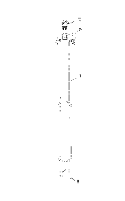
Fig. 1 shows a view of an enamelled baffle, into the inner
space of which a sensor arrangement in accordance
with the invention is built in,
Fig. 2 shows a sectional view of -the lower end of the baffle
in Fig. 1, in which the sensors are arranged,
Fig. 3 shows a sectional view of the measuring inser-t in
Fig. 2 in a premounted condition, and
Fig. 4 shows a view of the carrier in Figs. 2 and 3, at
which conduits are provided leading to the terminal
head in Fig. 1.
Fig. 1 shows an enamelled baffle~ which may be inserted as a
built in part e.g. into an enamelled agitator vessel. Of the
measuring sensor arrangement only the terminal head 16 is
shown, as well as a screw joint 15 comprising a wedge ring.
This joint serves for sealing the inner space of the baffle
against the atmosphere.
Fig. 2 shows a measuring sensor arrangement in accordance
with the invention, in which the measuring insert is shown
in the inserted condition. The measuring insert comprises
an elonga-ted carrier 2, along the length of which an out-
wardly protruding detent element 7 in the form of a
collar is provided. From the lower surface of the carrier 2
two measuring sensors 6 are protruding in the shown embodi-
ment. Normally one to four measuring sensors are provided,
the number of the measuring sensors depending on the measuring
functions to be performed.

--3--
The carrier 2 is slidably arranged in a longitudinal direction
in a guiding tube 4, the upper end of which protrudes from
the built in part 1 in Fig. 1 and is fixed in the inserted
'position by the sealing screwed joint 15 with a wedge ring.
In the guiding tube 4 a shoulder 13 is formed. Between the
shoulder 13 and the detent element 7 a spring 3 is inserted,
which presses the detent element 7 in the premounted position
against a s-top 5r which can be e.g. a snap ring inserted into
a groove in the inner wall of the guiding tube 4. The mounted
position is shown in Fig. 2, in which the de-tent elemen-t 7 is
raised from the stop 5. Preferably between -the carrier 2,which
is slidable in the longitudinal direction, and the inner wall
of the guiding tube ~ a radial clearance is provided, in order
that the carrier 2 can be tilted if necessary into the posi-tion,
in which the contact surfaces of the downwardly protruding
ends of the one or of the several measuring sensors 6 are
securely pressed against a thin walled bottom region 8.
The thin walled bottom region 8 which may have a thickness of
e.g. 3 mm is preferab]y provided with a coating 7 out of
silver. The coating out of silver can be provided in such a
manner, that e.g. a wafer out of silver having a thickness of
1 mm is soldered with a high temperature solder. Since the
coating out of silver is formed before enamelling, scaling of
the steel at the relatively high firing temperatures is avoi-
ded, which are necessary for enamelling. Furthermore, it is
assured by the silver coating, that after some operation time
no corrosion layer is formed which would diminish the heat
transfer. In comparison to other corrosion resistant layers
the use of silver having a high thermal conductivi-ty provides
for a higher response speed of the measuring sensors.
The coating 7 out of silver is provided above the lower end
of an insert bore 10, which is formed in the cap of the
enamelled built in part 1. The insert bore 10 is provided
at the upper end with a conical enlargement 11 for the insert
end 12 of the guiding tube, which insert end is preferably
shaped correspondingly. The con~cally enlarging insert bore
for the insert end 12 makes it possible, that the insert end
can be seated into the insert bore 10 in an easy manner during

:~ 3 ~
--4--
mounting.
For a further simplification of mounting it is advantageous
to weld a mountlng tube to the enamelled built in part 1,
which mounting tube surrounds the guiding tube ~.
During mounting the measuring insert the insert end of the
guiding tube comes into the position as shown in Fig. 2 by
pressing it downwardly, whereafter the screwed joint 15
shown in Fig. 1 is tightened, so that the shown position is
maintained.
The leads for the measuring sensors 6 as shown in Fig. 4 may
have a length of e.g. ~000 mm corresponding to the length of
the built in par-t. Such leads are protected along their
complete length by the guiding tube 4, so that during mounting
damages of the leads will not occur.

Dessin représentatif
Une figure unique qui représente un dessin illustrant l'invention.
États administratifs

2024-08-01 : Dans le cadre de la transition vers les Brevets de nouvelle génération (BNG), la base de données sur les brevets canadiens (BDBC) contient désormais un Historique d'événement plus détaillé, qui reproduit le Journal des événements de notre nouvelle solution interne.

Veuillez noter que les événements débutant par « Inactive : » se réfèrent à des événements qui ne sont plus utilisés dans notre nouvelle solution interne.

Pour une meilleure compréhension de l'état de la demande ou brevet qui figure sur cette page, la rubrique Mise en garde , et les descriptions de Brevet , Historique d'événement , Taxes périodiques et Historique des paiements devraient être consultées.

Historique d'événement

Description Date
Inactive : CIB de MCD 2006-03-11
Le délai pour l'annulation est expiré 2002-06-03
Lettre envoyée 2001-06-01
Accordé par délivrance 1993-06-01

Historique d'abandonnement

Il n'y a pas d'historique d'abandonnement

Historique des taxes

Type de taxes Anniversaire Échéance Date payée
TM (catégorie 1, 5e anniv.) - générale 1998-06-01 1998-05-04
TM (catégorie 1, 6e anniv.) - générale 1999-06-01 1999-05-03
TM (catégorie 1, 7e anniv.) - générale 2000-06-01 2000-05-03
Titulaires au dossier

Les titulaires actuels et antérieures au dossier sont affichés en ordre alphabétique.

Titulaires actuels au dossier
PFAUDLER WERKE GMBH
Titulaires antérieures au dossier
KARL WEISSMANN
RAINER TRAMPERT
REINHART SCHERTZ
Les propriétaires antérieurs qui ne figurent pas dans la liste des « Propriétaires au dossier » apparaîtront dans d'autres documents au dossier.
Documents

Pour visionner les fichiers sélectionnés, entrer le code reCAPTCHA :


Pour visualiser une image, cliquer sur un lien dans la colonne description du document. Pour télécharger l'image (les images), cliquer l'une ou plusieurs cases à cocher dans la première colonne et ensuite cliquer sur le bouton "Télécharger sélection en format PDF (archive Zip)" ou le bouton "Télécharger sélection (en un fichier PDF fusionné)".

Liste des documents de brevet publiés et non publiés sur la BDBC .

Si vous avez des difficultés à accéder au contenu, veuillez communiquer avec le Centre de services à la clientèle au 1-866-997-1936, ou envoyer un courriel au Centre de service à la clientèle de l'OPIC.


Description du
Document 
Date
(aaaa-mm-jj) 
Nombre de pages   Taille de l'image (Ko) 
Dessins 1993-11-30 2 32
Revendications 1993-11-30 2 54
Abrégé 1993-11-30 1 27
Description 1993-11-30 4 147
Dessin représentatif 2002-04-28 1 2
Avis concernant la taxe de maintien 2001-07-02 1 178
Taxes 1997-05-11 1 70
Taxes 1996-05-15 1 73
Taxes 1995-05-17 1 154
Correspondance de la poursuite 1992-06-11 3 90
Demande de l'examinateur 1992-03-26 1 61
Correspondance reliée au PCT 1993-02-25 1 32